Functional description
TF5200 | TC3 CNC
Single step mode
1.0
11/25/2020
Version
Notes on the documentation
Single step mode
TF5200 | TC3 CNC Version 1.0 3
Notes on the documentation
This description is only intended for the use of trained specialists in control and automation engineering who are familiar with the applicable national standards.
It is essential that the documentation and the following notes and explanations are followed when installing and commissioning the components.
It is the duty of the technical personnel to use the documentation published at the respective time of each installation and commissioning.
The responsible staff must ensure that the application or use of the products described satisfy all the requirements for safety, including all the relevant laws, regulations, guidelines and standards.
Disclaimer
The documentation has been prepared with care. The products described are, however, constantly under development.
We reserve the right to revise and change the documentation at any time and without prior announcement. No claims for the modification of products that have already been supplied may be made on the basis of the data, diagrams and descriptions in this documentation.
Trademarks
Beckhoff®
, TwinCAT®
, EtherCAT®
, EtherCAT G®
, EtherCAT G10®
, EtherCAT P®
, Safety over EtherCAT®
, TwinSAFE®, XFC®, XTS® and XPlanar® are registered trademarks of and licensed by Beckhoff Automation
GmbH.
Other designations used in this publication may be trademarks whose use by third parties for their own purposes could violate the rights of the owners.
Patent Pending
The EtherCAT technology is patent protected, in particular by the following applications and patents: EP1590927, EP1789857, EP1456722, EP2137893, DE102015105702
with corresponding applications or registrations in various other countries.
EtherCAT® is registered trademark and patented technology, licensed by Beckhoff Automation GmbH,
Germany
Copyright
© Beckhoff Automation GmbH & Co. KG, Germany.
The reproduction, distribution and utilisation of this document as well as the communication of its contents to others without express authorisation are prohibited.
Offenders will be held liable for the payment of damages. All rights reserved in the event of the grant of a patent, utility model or design.
General and safety instructions
Single step mode TF5200 | TC3 CNC
4 Version 1.0
General and safety instructions
Icons used and their meanings
This documentation uses the following icons next to the safety instruction and the associated text. Please read the (safety) instructions carefully and comply with them at all times.
Icons in explanatory text
ØIndicates an action.
ð Indicates an action statement.
DANGER
Acute danger to life!
If you fail to comply with the safety instruction next to this icon, there is immediate danger to human life and health.
CAUTION
Personal injury and damage to machines!
If you fail to comply with the safety instruction next to this icon, it may result in personal injury or damage to machines.
NOTICE
Restriction or error
This icon describes restrictions or warns of errors.
Tips and other notes
This icon indicates information to assist in general understanding or to provide additional informa-tion.
General example
Example that clarifies the text.
NC programming example
Programming example (complete NC program or program sequence) of the described function or NC com-mand.
Specific version information
Optional or restricted function. The availability of this function depends on the configuration and the scope of the version.
Table of contents
Single step mode
TF5200 | TC3 CNC Version 1.0 5
Table of contents
Notes on the documentation ... 3
General and safety instructions ... 4
1 Overview... 8
2 Description of the various operation modes ... 9
3 Disable program areas for single step ... 10
4 Single step mode on block numbers ... 12
5 Parameter ... 15
5.1 Overview... 15
5.2 Description... 15
6 Interfacing ... 16
6.1 Selection via HMI interface ... 16
7 Support and Service... 17
Table of contents
Single step mode TF5200 | TC3 CNC
List of figures
Single step mode
TF5200 | TC3 CNC Version 1.0 7
List of figures
Overview
Single step mode TF5200 | TC3 CNC
8 Version 1.0
1
Overview
Task
When single step mode is active, the machine operator has the option to execute an NC program step by step. The operator enables every NC line one by one. Comment lines or comment blocks and skipped blocks are skipped.
Characteristics
The NC program sequence is interrupted at block boundaries in the interpolator. The sequence during decoding or in look-ahead mode is not affected. As a result, path-correcting functions such as spline or tool radius compensation can also be active in single step mode.
However, path-changing functions can also shift block boundaries. For single step mode, the shifted block boundaries are active, if applicable, but not the programmed block boundaries.
Parameterisation
Single step mode is activated by the channel parameter @@P-CHAN-00015. When single step mode is activated, a stop is executed at the end of NC blocks depending on this parameter [} 15] and depending on a number of criteria.
Programming
The NC command #SINGLE STEP [DISABLE | ENABLE] [} 10] can block whole program areas to single step mode. This program area is then skipped in a complete single step.
The NC command #SINGLE STEP [RESOLUTION..] [} 12] defines a block number related resolution for a single step.
Links to other documents
For the sake of clarity, links to other documents and parameters are abbreviated, e.g. [PROG] for the Programming Manual or P-AXIS-00001 for an axis parameter.
For technical reasons, these links only function in the Online Help (HMTL5, CHM) but not in pdf files since pdfs do not support cross-linking.
Description of the various operation modes
Single step mode
TF5200 | TC3 CNC Version 1.0 9
2
Description of the various operation modes
Select
Single step and its operation modes can be set at any time by operator action or the PLC. The following operation modes are available:
0 : Step into
The "Step into" single step mode is active by default. This means that program execution is again interrupted when subroutines are invoked at the first block in the subroutine.
Single step acts on every programmed NC line which is processed during the program sequence.
1 : Step over
The "Step over" mode can be set if the NC lines contained in a subroutine are not to be executed in single steps. This means that any subroutine invocation which may exist in the next step does not result in a stop. Program execution is continued without stopping until the subroutine is terminated.
This characteristic also applies to nested subroutines.
2 : Return from function
All subsequent instructions do not result in a stop. Only a return from the current program level again results in a stop of the NC program.
If the current interrupt point is already at the topmost level, i.e. the main program, this mode acts in the same way as "Step into".
Disable program areas for single step
Single step mode TF5200 | TC3 CNC
10 Version 1.0
3
Disable program areas for single step
Selection
Individual program areas can be disabled in single step mode by the command #SINGLE STEP [ DISABLE / ENABLE ]. This continues the complete area using single step. No stop is executed within the grey area.
#SINGLE STEP [ DISABLE | ENABLE ] (modal)
The program area N40–N100 written in italics and the subroutine invocation are not executed in single step mode.
%SINGLE_STEP N10 X0 Y0 Z0 N20 X10 N30 Y10
N40 #SINGLE STEP [DISABLE]
N50 X20 N60 Y20 N65 L GSP.nc N70 Z20 N80 X30 N90 Z30
N100 #SINGLE STEP [ENABLE] N110 Y30
N120 X40 N130 Z40 N999 M30
Nested disable/enable
When disable/enable commands are nested, the single step disable includes the area beginning from the first disable to the first enable (see example below)
Disable program areas for single step
Single step mode
TF5200 | TC3 CNC Version 1.0 11
In the following nested areas, single step mode in the area displayed in italics is disabled between N40-N75.
%SINGLE_STEP N10 X0 Y0 Z0 N20 X10 N30 Y10
N40 #SINGLE STEP [DISABLE]
N50 X20
N55 #SINGLE STEP [DISABLE]
N60 Y20 N65 L GSP.nc N70 Z20
N75 #SINGLE STEP [ENABLE] N80 X30
N90 Z30
N100 #SINGLE STEP [ENABLE]
N110 Y30 N120 X40 N130 Z40 N999 M30
Single step mode on block numbers
Single step mode TF5200 | TC3 CNC
12 Version 1.0
4
Single step mode on block numbers
Block number
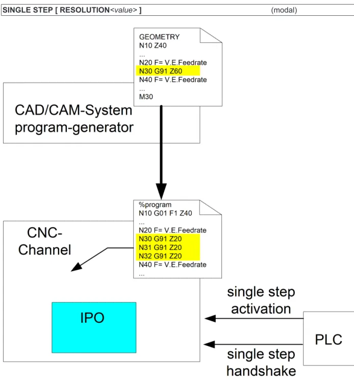
When single step mode is enabled, the CNC stops before each new motion block (see P-CHAN-00015 [} 15]) and waits for an acknowledgement from the PLC.
If the NC program was automatically generated by a post-processor based on CAD/CAM data, the original geometry information may result in several NC motion blocks. In this case a single step should correlate with the original granularity of CAD/CAM data and only stop at the original geometric resolution.
Another possible application case may be to explicitly disable single step mode for individual blocks.
SINGLE STEP [ RESOLUTION<value>] (modal)
Single step mode on block numbers
Single step mode
TF5200 | TC3 CNC Version 1.0 13
Block number related single step resolution
As an additional option the user can define block number related single step resolution. 0: Off, no single step related to block numbers,
Stop before each NC line
1: Single step stops before each new programmed NC block number > 1: A stop is executed before each block which can be divided into an integer with no remainder.
<<Integer result> = <Block number> / <Resolution>
< 0: Impermissible value for single step resolution, an error message is output.
The single step resolution to block numbers was set to 10.
In this case a stop is executed before each block can be divided by 10 into an integer with no remainder. No stop is executed in the area displayed in italics in single step mode. The black lines show the single-step stop.
%single_step
N000 #SINGLE STEP [RESOLUTION = 10]
________________ N000 X0 ________________ N010 X1 N011 X1.1 N012 X1.2 ________________ N020 X2 ________________ N030 X3 … ________________ N090 X9 N091 Y0 N092 Y1 N093 Y2 N094 Y3 N095 Y4 ________________ N100 Y5 N101 Y6 N102 Y7 ________________ N110 Y8 …
To ensure effective diagnosis, all NC lines should always be provided with a unique
block number.
Block numbering with user resolution (steps of ten) and internal numbering (single step width).
%single_step
N010 #SINGLE STEP [RESOLUTION = 10]
________________ N090 Y0
Single step mode on block numbers
Single step mode TF5200 | TC3 CNC
14 Version 1.0
N092 Y2 N093 Y3 N094 Y4
________________ N100 Y5
N101 Y6 N102 Y7
________________ N110 Y8
Parameter
Single step mode
TF5200 | TC3 CNC Version 1.0 15
5
Parameter
5.1
Overview
ID Parameter Description
P-CHAN-00015 Einzelschrittmodus Operation mode of single step mode
5.2
Description
P-CHAN-00015 Define single-step operating mode
Description If the parameter is set to -1 and single-step mode is activated, it is only possible to stop by operator action at the end of NC blocks with axis movements.
If the parameter is set to 0 and single-step mode is activated, it is only possible to stop by operator action at the end of NC blocks with axis movements and other NC blocks with relevant control information.
If the parameter is set to 1 and single-step mode is activated, it is only possible to stop by operation action at the end of every NC block. Only comment lines are skipped.
If motion blocks are inserted by specific NC functionality (TRC, SPLINE, polynomial smoothing over, etc.) and block boundaries are altered, these new block boundaries also determine stopping in the single step mode.
Parameter einzelschrittmodus Data type SGN16
Data range -1: Single-step mode only for NC motion blocks
0: Single-step mode for NC motion blocks and relevant control blocks (default) 1: Single-step mode for all NC blocks
Dimension ----Default value 0 Remarks
Interfacing
Single step mode TF5200 | TC3 CNC
16 Version 1.0
6
Interfacing
6.1
Selection via HMI interface
The single step operation mode is set by the PLC writing the modifier before the next step. The operation mode is modal.
Single step operation mode
Description The PLC can select the type of single step operation mode using this interface element.
Type 4 Byte Value range 0: Step into
1: Step over
2: Return from function
HMI elements Can currently be used as CNC object only. Access Read, write
Address GEO task
IndexOffset = 0x1A
Support and Service
Single step mode
TF5200 | TC3 CNC Version 1.0 17
7
Support and Service
Beckhoff and their partners around the world offer comprehensive support and service, making available fast and competent assistance with all questions related to Beckhoff products and system solutions.
Beckhoff Support
Support offers you comprehensive technical assistance, helping you not only with the application of individual Beckhoff products, but also with other, wide-ranging services:
• Support
• design, programming and commissioning of complex automation systems • and extensive training program for Beckhoff system components
Hotline: +49(0)5246/963-157
Fax: +49(0)5246/963-9157
E-mail: [email protected]
Beckhoff Service
The Beckhoff Service Center supports you in all matters of after-sales service: • on-site service
• repair service • spare parts service • hotline service
Hotline: +49(0)5246/963-460
Fax: +49(0)5246/963-479
E-mail: [email protected]
Further Support and Service addresses can be found on our website at http://www.beckhoff.de.
Beckhoff headquarters
Beckhoff Automation GmbH & Co. KG Hülshorstweg 20 33415 Verl Germany Phone: +49(0)5246/963-0 Fax: +49(0)5246/963-198 E-mail: [email protected]
The addresses of Beckhoff’s branch offices and representatives round the world can be found on the internet pages:
http://www.beckhoff.de
Index
Single step mode TF5200 | TC3 CNC
18 Version 1.0