Chapter 2
ELECTROMAGNETIC HORN ANTENNAS
Paul Wade N1BWT © 1994,1998
A horn antenna is the ideal choice for a rover station. It offers moderate gain in a small, rugged package with no adjustments needed, and has a wide enough beam to be easily pointed under adverse conditions. Figure 2-1 is a photograph of a homebrew horn mounted on an old Geiger counter case which houses the rest of a 10 GHz WBFM transceiver. I have worked six grid squares on 10 GHz from Mt. Wachusett in Massachusetts using only a small horn with 17.5 dB gain.
Horn Design
An antenna may be considered as a transformer from the impedance of a transmission line to the impedance of free space, 377 ohms. A common microwave transmission line is waveguide1, a hollow pipe carrying an electromagnetic wave. If one dimension of the pipe is greater than a half wavelength, then the wave can propagate through the waveguide with extremely low loss. And if the end of a waveguide is simply left open, the wave will radiate out from the open end.
Practical waveguides have the larger dimension greater than a half wavelength, to allow wave propagation, but smaller than a wavelength, to suppress higher-order modes which can interfere with low-loss transmission. Thus the aperture of an open-ended waveguide is less than a wavelength, which does not provide much gain.
For more gain, a larger aperture is desirable, but a larger waveguide is not. However, if the waveguide size is slowly expanded, or tapered, into a larger aperture, then more gain is achieved while preventing undesired modes from reaching the waveguide. To achieve maximum gain for a given aperture size and thus maximum efficiency, the taper must be long enough so that the phase of the wave is nearly constant across the aperture. In cylindrical waveguide, a funnel-like taper is called a conical horn. The conical horn for 2304 MHz shown in Figure 2-2 was made by pop-rivetting aluminum flashing to a coffee can. In common rectangular waveguide, the taper creates a familiar pyramidal horn, like those shown in the photograph, Figure 2-3.
Pyramidal Horns
An optimum horn is the shortest one that approaches maximum gain; several definitions are available. The HDL_ANT program uses approximate dimensions from a set of tables2 by Cozzens to design pyramidal horn antennas with gains from 10 to 25 dB. Higher gains are possible, but the length of the horn increases much faster than the gain, so very high gain horns tend to be unwieldy.
For pyramidal horns, Kraus3 gives the following approximations for 3 dB beam width in degrees and dB gain over a dipole:
E
plane = e56
A
λ degreesH
plane = h67
A
λ degreesand for gain
(
)
G
≅
10log
104.5A A
⋅
eλ⋅ hλ dB over dipolewhere
A
eλ is the aperture dimension in wavelengths in the E-plane andA
hλis the aperture in wavelengths dimension in the H-plane.The HDL_ANT program uses a more accurate gain algorithm4 which corrects the phase error of different taper lengths; for a given aperture, efficiency and gain decrease as the taper is shortened.
For some applications, the beamwidth at power levels other than 3 dB down is useful. For instance, the feed for a parabolic dish is often specified as having a pattern which is 10 dB down at the edge of the dish. For a simple horn, the 10 dB beamwidth is roughly 1.8 times the 3dB beamwidth. Other points in the main beam may be approximated using Kelleher’s5 universal horn patterns:
P
dB( )
θ
θ
θ
10
10≅
2where
P
dB( )
θ
is the relative power at angleθ
from the center of the beam, andθ
10is the angle where the power is 10 dB down from maximum.Conical Horns
For conical horns, an optimum horn is one which provides the desired gain with the minimum amount of material. The HDL_ANT program uses an algorithm from Jasik6 to design optimum conical horn antennas with gains between 10 and 25 dB. Again, higher gains are possible, but probably unwieldy.
The HDL_ANT program will calculate gain for conical horns of any dimension, using another algorithm from Jasik7
.
Horn Construction
If you are fortunate enough to find a suitable surplus horn, then this section is unnecessary. Otherwise, you may want to homebrew one. Horn fabrication is quite simple, so we can homebrew them as needed, for primary antennas with moderate gain or as feeds for higher gain dishes and lenses. Performance of the finished horn almost always matches predictions, with no tuning adjustments required.
The HDL_ANT program will design a horn with any desired gain or physical dimensions and then make a template for the horn. The template is a PostScriptTM file; print the file on a computer printer (see Appendix 1 for details on printing a PostScript file) to
generate a paper template, tape the paper template to a sheet of copper or brass, and cut it out.
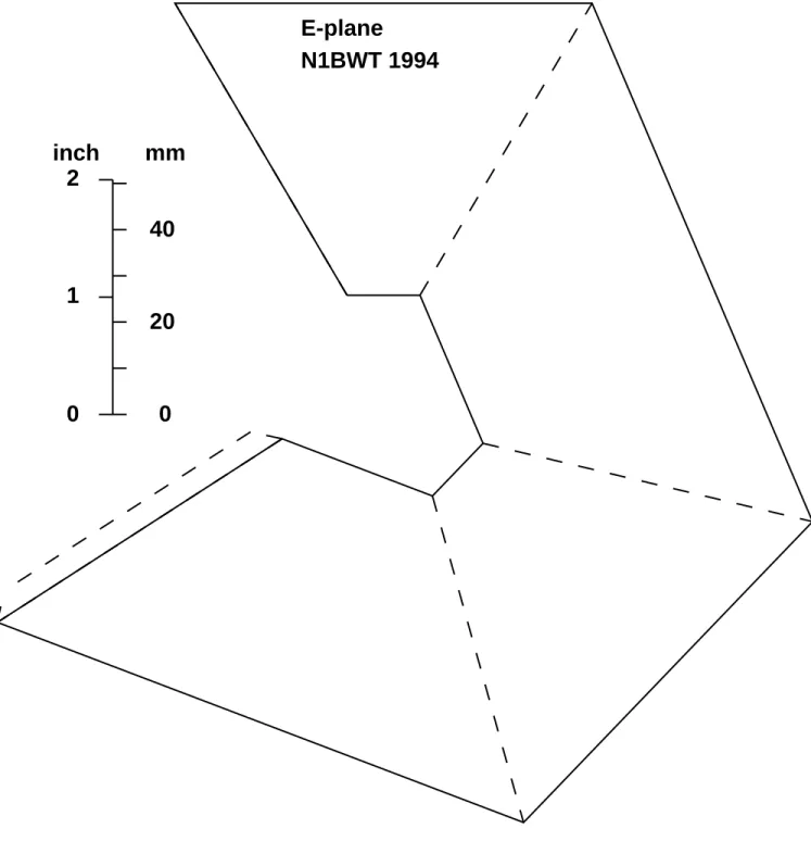
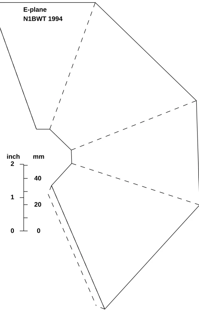
If the template is for a pyramidal horn, fold on the dotted lines, and solder the metal horn together on the end of a waveguide. The horn shown in Figure 2-1 used flashing copper from the local lumberyard, which I soldered together on the kitchen stove. Figure 2-4 is a template for a nominal 14 dB horn for 5760 MHz generated by HDL_ANT. Try it: copy it on a copier and fold up the copy to see how easy it is to make a horn. It's almost as easy with thin copper. Figure 2-5 is another template example, a nominal 18 dB horn for 10368 MHz. For horns too large to fit the entire template on one sheet of paper,
HDL_ANT prints each side on a separate sheet.
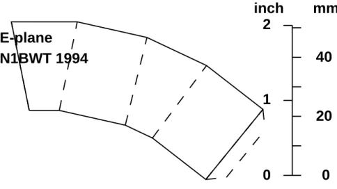
Templates for conical horns are even simpler: just two concentric sections of a circle, like Figure 2-6, a nominal 14 dB horn for 10368 MHz. When the two straight edges are joined together, a cone is formed. In metal, we solder the two edges together and then solder it to the cylindrical waveguide. For cylindrical horns too large to fit the entire template on one sheet of paper, HDL_ANT displays the dimensions necessary to do layout with a compass and straightedge.
Feed Horns
For horns intended as feed horns for dishes and lenses, beam angle and phase center are more important than horn gain. For pyramidal horns, the HDL_ANT program calculates these values in both the E-plane and the H-plane, then allows you to enter new horn dimensions to adjust the beam angle or phase center before making a template. The phase center calculation is a difficult one6 involving Fresnel sines and cosines8, so interactive adjustment of horn dimensions is a lot easier than having the computer try to find the right dimensions. The template in Figure 2-7 is one example of a feed horn — it may be used to make a rectangular horn optimized to feed a dish9 with f/D = 0.5 at 10 GHz. Feed horn design for dishes and lenses will be described in more detail later.
Figure 2-4. Template for 13.84 dBi horn for 5760 MHz
E-plane
N1BWT 1994
0
0
1
2
20
40
inch
mm
Figure 2-5. Template for 17.97 dBi horn for 10368 MHz
E-plane
N1BWT 1994
0
0
1
2
20
40
inch
mm
Figure 2-6. Template for 14 dBi conical horn for 10368 MHz
N1BWT 1998
0
0
1
2
20
40
inch
mm
Figure 2-7. Feedhorn Template
Figure 2-7. Template for 8.05 dBi horn for 10368 MHz
E-plane
N1BWT 1994
0
0
1
2
20
40
inch
mm
Conclusion
Horns are versatile microwave antennas, easy to design and build with predictable performance. They should be the antenna of choice for all but the highest gain applications.
References
1. The ARRL UHF/Microwave Experimenter's Manual, ARRL, 1990, pp. 5-21 to
5-32.
2. D.E. Cozzens, "Tables Ease Horn Design," Microwaves, March 1966, pp. 37-39. 3. John Kraus (W8JK), Antennas, McGraw Hill, 1956.
4. C.A. Balanis, "Horn Antennas," in Antenna Handbook: theory, applications, and design, Y.T. Lo and S.W. Lee, editors, Van Nostrand Reinhold, 1988, page 8-39. 5. C.M. Knop & H.J. Wiesenforth, “On the Ratiation from an Open-Ended Corrugated
Pipe Carrying the HE11 Mode,” IEEE Transactions on Antennas andPropagation,
Sept. 1972, pp. 640-648.
6. H. Jasik, Antenna Engineering Handbook, First Edition, Mcgraw-Hill, 1961, p.10-11.
7. Eugen I Muehldorf, “The Phase Center of Horn Antennas," reprinted in A. W. Love,
Electromagnetic Horn Antennas, IEEE Press, 1976.
8. Milton Abramowitz and Irene A. Stegun, Handbook of Mathematical Functions, Dover, 1972.
9. D. Evans, G3RPE, "Pyramidal horn feeds for paraboloidal dishes," Radio