O R I G I N A L R E S E A R C H
Open Access
An improved MPPT control strategy based
on incremental conductance algorithm
Liqun Shang
*, Hangchen Guo and Weiwei Zhu
Abstract
PV power production is highly dependent on environmental and weather conditions, such as solar irradiance and ambient temperature. Because of the single control condition and any change in the external environment, the first step response of the converter duty cycle of the traditional MPPT incremental conductance algorithm is not accurate, resulting in misjudgment. To improve the efficiency and economy of PV systems, an improved incremental conductance algorithm of MPPT control strategy is proposed. From the traditional incremental conductance algorithm, this algorithm is simple in structure and can discriminate the instantaneous increment of current, voltage and power when the external environment changes, and so can improve tracking efficiency. MATLAB simulations are carried out under rapidly changing solar radiation level, and the results of the improved and conventional incremental conductance algorithm are compared. The results show that the proposed algorithm can effectively identify the misjudgment and avoid its occurrence. It not only optimizes the system, but also improves the efficiency, response speed and tracking efficiency of the PV system, thus ensuring the stable operation of the power grid.
Keywords:Photovoltaic array, MPPT, Phenomenon of misjudgment, Incremental conductance algorithm
1 Introduction
With the deterioration of the environment and the de-pletion of conventional energy sources, solar energy as a new type of green energy has attracted widespread atten-tion throughout the world [1, 2]. Photovoltaic (PV) power generation is the most common form of solar energy generation. The output power of a single PV cell, which is the basic unit of PV power generation, is relatively low. In practical applications, given the requirements of voltage and power, it is necessary to combine multiple PV modules in series and parallel to form a PV array. PV array output current and volt-age are affected by meteorological conditions (irradi-ance, temperature etc.) and thereby appear to be non-linear. Its output power also changes continuously. Therefore, how to adjust the load characteristics so that the system can output the maximum power in
real time, namely, to achieve the maximum power point tracking (MPPT), is particularly important in PV systems [3–5].
MPPT methods mainly include traditional methods and intelligent control algorithms [6]. Traditional MPPT methods include hill climbing [7, 8], perturbation and observation [9, 10], and incremental conductance methods [11,12], while intelligent control algorithms in-clude fuzzy-logic [13], artificial neural networks [14], flower pollination algorithm [15], and particle swarm optimization [16,17]. Although the effectiveness of intel-ligent control algorithms has been verified by experi-ments in many cases, the algorithms still have the disadvantages of high complexity and slow convergence speed, so have been less applied in real projects. The in-cremental conductance method is currently the most widely used direct control method.
© The Author(s). 2020Open AccessThis article is licensed under a Creative Commons Attribution 4.0 International License, which permits use, sharing, adaptation, distribution and reproduction in any medium or format, as long as you give appropriate credit to the original author(s) and the source, provide a link to the Creative Commons licence, and indicate if changes were made. The images or other third party material in this article are included in the article's Creative Commons licence, unless indicated otherwise in a credit line to the material. If material is not included in the article's Creative Commons licence and your intended use is not permitted by statutory regulation or exceeds the permitted use, you will need to obtain permission directly from the copyright holder. To view a copy of this licence, visithttp://creativecommons.org/licenses/by/4.0/. * Correspondence:[email protected]
At present, the development direction of the MPPT algorithm is mainly on the continuous optimization of PV system mathematics and control model [18, 19]. Because of the direct control of converter duty cycle, there is no need to adjust other parameters. This sim-plifies the MPPT control structure and has good con-trol performance when the external environment is stable. However, the algorithm needs to constantly apply disturbance to the duty cycle to determine the maximum power point (MPP), and thus when the ex-ternal environment changes, the working point may deviate from the correct tracking trajectory, resulting in misjudgment. This would affect the response speed and tracking accuracy of the system, and result in power loss [20, 21].
To maintain a fast response speed and high steady-state accuracy of the PV system under changing environ-mental conditions, this paper proposes an improved in-cremental conductance method. The MPPT control system is different from the module building method adopted at present, and combined with an optimized control algorithm, it can achieve a more accurate, faster and more stable tracking effect.
2 PV array characteristic
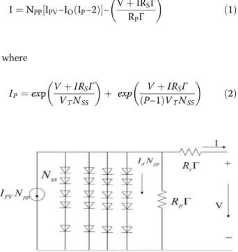
Considering economy and maintainability, centralized inverter topologies are generally used in PV power gen-eration systems. Centralized inverters are connected to a large number of PV modules, usually using S-P configur-ation, as shown in Fig.1. The output current of this con-figuration can be expressed as [22]:
I¼NPP½IPV−IOðIP−2Þ−
VþIRSΓ RPΓ
ð1Þ
where
IP¼exp VþIRSΓ VTNSS
þ exp VþIRSΓ P−1
ð ÞVTNSS
ð2Þ
Γ¼ NSS
NPP ð
3Þ
I and V are the solar cell output current and voltage, respectively. IPV is the photocurrent, IO is the reverse saturation current, and VT is the thermal voltage of PV arrays. RS and RP are the equivalent series and parallel resistances, respectively.
The output characteristics of PV cells are closely re-lated to the solar irradiance. When solar irradiance changes, the PV array has strong nonlinear volt-ampere characteristics. It is neither a constant voltage nor a con-stant current, and cannot provide concon-stant power for load. The output current is approximately constant in most of the working voltage range, though near the open circuit voltage, the current decline rate is very large.
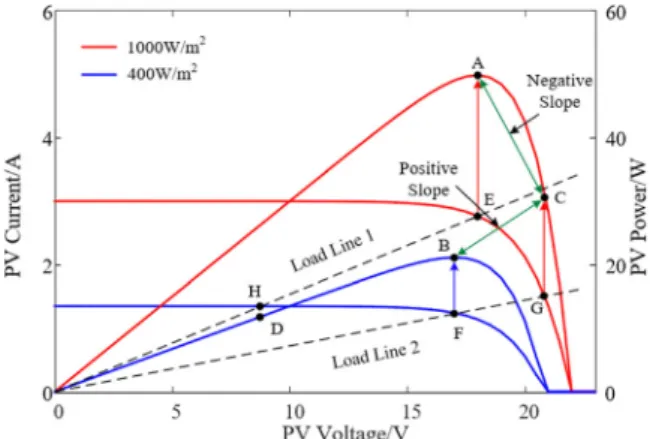
Figure 2 shows the simulation results under different solar irradiance at the PV array temperature of T = 25 °C. It can be seen from the figure that the output characteristics of the photovoltaic array vary greatly under the influence of solar irradiance. When the solar irradiance increases, the output power increases.
3 Proposed incremental conductance algorithm
3.1 Conventional incremental conductance algorithm
The incremental conductance algorithm detects the slope of the P–V curve, and the MPP is tracked by searching the peak of the P–V curve. This algorithm uses the instantaneous conductance I/V and the incre-mental conductance dI/dV for MPPT. Depending on the relationship between the two values, as expressed in (4)–(6), the location of the operating point of the PV module in the P–V curve can be determined, i.e., (4) in-dicates the PV module operates at the MPP, whereas (5) and (6) indicate the PV module operates at the left and right side of the MPP in the P–V curve, respectively.
di dv¼−
I
V ð4Þ
Fig. 1Equivalent circuit of S-P configuration of PV array
di dv>−
I
V ð5Þ
di dv<−
I
V ð6Þ
The above equations are obtained from the concept where the slope of the P–V curve at MPP is equal to zero, i.e.:
dp dv¼
0 ð7Þ
By rewriting (7), the following equation is obtained:
IþVdi dv
¼0 ð8Þ
In the conventional incremental conductance algo-rithm, (8) is used to detect the MPP, and the voltage and current of the PV module are measured by the MPPT controller. If (5) is satisfied, the duty cycle of the con-verter needs to be decreased, and vice versa if (6) is sat-isfied, whereas no change on the duty cycle if (8) is satisfied [23].
3.2 Weakness of conventional incremental conductance algorithm
The conventional algorithm can be confused when the solar irradiation increases. As shown in Fig. 3, when the irradiation is at 0.4 kW/ m2, the MPPT al-gorithm adjusts the duty cycle to ensure that the PV system operates at load line 2 and the MPP (point B) is tracked. After some time, the solar irradiation increases to 1.0 kW/ m2, but the duty cycle is main-tained at load line 2. Therefore, point G will be found by load line 2 in the I–V curve of 1.0 kW/
m2, corresponding to the power at point C in the P–
V curve. The conventional incremental conductance algorithm calculates the gradient between points B
and C to be positive. However, the gradient between point C and the MPP (point A) of 1.0 kW/m2has a nega-tive value. Without noticing this error, the conventional algorithm increases the voltage of the PV module, result-ing in an inaccurate first step change when solar irradi-ation level changes from low to high. However, this problem does not occur when the solar irradiation level decreases from high to low. This is because from points E to H, or in the P–V curve from points A to D, the gradient is positive, while the gradient between points B and D is also positive [24].
3.3 Proposed incremental conductance algorithm
The incremental conductance algorithm depends on the slope of the P–V curve, which is affected by the solar ir-radiation level and load resistance. As the algorithm uses the current and voltage of the PV module in the calcula-tion, the effect of solar irradiation and load changes on the current and voltage of the PV module must be con-sidered in the algorithm.
Table 1 shows the summary of changes in the voltage and current of the PV module against the changes in solar irradiation level and load resistance. As shown in Fig. 3, when the PV system operates at load line 2 (point F) and solar irradiation suddenly increases, the operating point of the PV system moves to point G. Therefore, both voltage and current increase. Conversely, when the PV system operates at load line 1 (point E) and solar irradiation suddenly de-creases, the operating point of the PV system moves to point H. Thus, both voltage and current decrease. In the conventional incremental conductance algo-rithm, these two types of changes are not properly considered. Meanwhile, if the PV system operates at load line 1 and load resistance increases, the PV sys-tem will operate at load line 2. Therefore, the PV module voltage increases and the PV module current decreases. Alternatively, the voltage decreases and
the current increases when the load resistance
decreases.
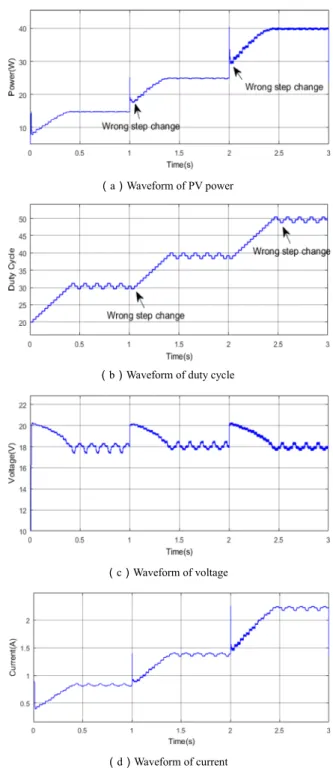
Figures 4 and 5 show the changes of duty cycle under small and large perturbations of irradiance, respectively. In Fig. 4, the irradiance starts from 0.4 kW/ m2, increases to 0.5 kW/ m2 at 1 s, and to 0.55 kW/ m2 at 2 s. In Fig. 5, the irradiance starts
Fig. 3I–V and P–V curves of irradiation 1000 W/m2and 400 W/m2
Table 1Changes in PV voltage and current during changes in solar irradiation and load resistance
dV dI
Solar Increase Increase
Irradiation Decrease Decrease
Load Increase Increase Decrease
from 0.3 kW/ m2, increases to 0.5 kW/ m2 at 1 s and to 0.8 kW/ m2 at 2 s. It can be seen from the figures that under the traditional algorithm, during both small and large irradiance disturbances, the system will deviate.
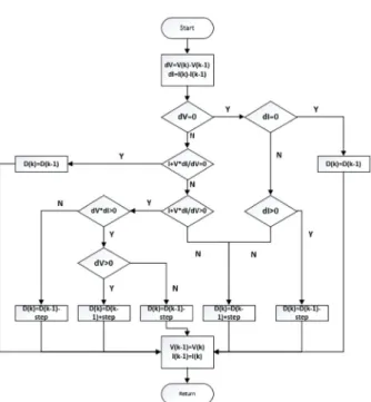
The proposed algorithm is shown in the flow chart in Fig. 6. When the irradiance changes, the current and voltage will be affected accordingly. This algo-rithm thus uses the instantaneous changes of current and voltage of PV modules. While the traditional in-cremental conductance algorithm makes a judgment on the position of the system operating point, the improved incremental conductance algorithm makes a judgment based on the directions of power, voltage and current. Considering the system at the left side of the MPP, for the system running in the positive direction (dv > 0) the duty cycle will continue to move in the disturbance direction of the previous step, while for the system running in the negative direction (dv < 0) the duty cycle will continue to move in the opposite direction of the disturbance of the previous step. Similarly, when the system is at the right side of the MPP, for the positive system running direction (dv > 0) the duty cycle will con-tinue to move in the opposite direction of the dis-turbance of the previous step, whereas for the negative system operating direction (dv < 0), the duty
cycle will continue to move in the direction of the disturbance of the previous step. Therefore, the algo-rithm can accurately and correctly judge the disturb-ance direction of the next step of the working point, thus solving the system misjudgment phenomenon in the traditional method.
4 Simulation results and analysis
Simulations are carried out using the MATLAB 2017a software platform and the Solarex-MX60 data of the PV module customized by BP Solar. The parameters under standard test conditions (STC) are presented in Table2, and the simulation model for the converter of the PV system with the proposed MPPT algorithm is shown in Fig. 7. The following specifications for the boost converter are used: C1= 470μF, C2=
47μF, L= 0.1 mH, switching frequency of 10 kHz, and load resistance of 78Ω. Furthermore, to ensure the system has attained a steady state before an-other MPP cycle is initiated, the sampling time is chosen to be 0.05 s.
The calculation of the sampling time is given as:
Fig. 4Change of duty cycle under slight disturbance
Fig. 5Change of duty cycle under strong disturbance
Fig. 6Flow chart of the proposed incremental conductance algorithm
Table 2Parameters of the MSX-60 PV model at STC
Maximum power (Pmpp) 49.8 W
Voltage ofPmax (Vmpp) 17.9 V
Current ofPmax (Impp) 2.77A
Open-circuit voltage (Voc) 22 V
Tε≅δ−∙1
wn∙
lnε ð9Þ
wherewn¼1= ffiffiffiffiffiffiffiffi L∙C
p
,δ¼1=ð2∙RMPPÞ∙ ffiffiffiffiffiffiffiffi L∙C
p
,ε= 0.1.
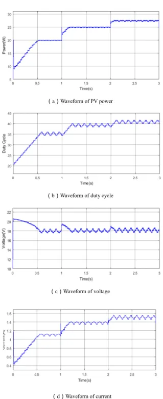
The irradiance is set to start from 0.3 kW/ m2, in-creases to 0.5 kW/ m2 at 1 s and to 0.8 kW/ m2 at 2 s. Under the same conditions, the performance of the trad-itional incremental conductance method and the pro-posed algorithm are compared.
Figures 8 and 9 show the simulation results of the traditional incremental conductance method and the proposed algorithm under strong irradiance changes. A contrast can be seen in that when the irradiance increases from 0.3 kW/ m2 to 0.5 kW/
m2, the response time of the traditional algorithm is 0.39 s while for the proposed algorithm it is 0.30s, indicating a tracking speed increase of 23.1%. The average output powers of the PV array are 25.09 W and 25.1 W, respectively. When the irradi-ance increases from 0.5 kW/ m2 to 0.8 kW/ m2, the response time is 0.43 s for the traditional algorithm and 0.35 s for the proposed algorithm, indicating a tracking speed increase of 18.6%. The average out-put powers of the PV array are 40.01 W and 40.18 W, respectively.
In addition, the proposed algorithm is also applicable to a small change of irradiance. The irradiance starts from 0.4 kW/ m2, increases to 0.5 kW/ m2at 1 s and to 0.55 kW/m2at 2 s.
The performance of the traditional method and the proposed algorithm is compared in Figs. 10 and 11. Again when the irradiance increases from 0.4 kW/
m2 to 0.5 kW/ m2, the response time is reduced by 33.3% from 0.24 s with the traditional algorithm to 0.16 s with the proposed algorithm. The average out-put powers of the PV array are 25.05 W and 25.1 W, respectively. When the irradiance increases from 0.5 kW/ m2 to 0.55 kW/ m2, the response time of the traditional algorithm is 0.08 s while the proposed al-gorithm is 0.05 s, indicating a tracking speed increase of 37.5%. The average output powers of the PV array are 27.55 W and 27.61 W, respectively.
In summary, compared with the traditional incre-mental conductance method, the proposed algorithm has the ability to solve misjudgment during irradiance variation, and the tracking speed is increased by 20% ~ 30% for different irradiance variation ranges. It not only solves the misjudgment phenomenon when the irradiance changes, but also effectively improves the
Fig. 7PV system with the boost converter
response speed of the system, reduces the power loss in the tracking process, and improves the output effi-ciency of the system.
5 Conclusion
In this paper, an incremental conductance algo-rithm is proposed to track the MPP for a PV
module under a fast-changing solar irradiation level. The confusion faced by the conventional algorithm is discussed and modifications are proposed to miti-gate the inaccurate response. Compared with the current research status, the control system structure of the proposed algorithm is simpler and more stable, and can accurately respond and track MPP.
Fig. 9simulation results of the proposed algorithm under strong disturbance.aWaveform of PV power.bWaveform of duty cycle.cWaveform of voltage.dWaveform of current
This improves the stability of the system and avoids misjudgment when the irradiance changes. Simula-tion results validate that the algorithm is more stable than the traditional algorithm, and improves not only the tracking speed but also the tracking accuracy of the system. The proposed algorithm has a similar structure to the conventional method and
no additional hardware components are needed in implementation. It can thus be easily implemented using a low-cost microcontroller, increasing the likelihood of the method being adopted in real PV power generation systems.
Abbreviations
PV:Photovoltaic; MPP: Maximum power point; MPPT: Maximum power point tracking; STC: Standard test conditions;P-V: Power-voltage;P-D: Power-duty cycle
Acknowledgements
Not applicable.
Authors’contributions
Shang was a major contributor in writing the manuscript. Guo performed the simulation examination. Guo and Zhu analyzed and interpreted the simulation results. All authors read and approved the final manuscript.
Funding
The Project Supported by Natural Science Basic Research Plan in Shaanxi Province of China (Program No. 2019JM-544).
Availability of data and materials
The datasets used and analyzed during the current study are available from the corresponding author.
Competing interests
The authors declare that we have no competing interests.
Received: 2 March 2020 Accepted: 2 June 2020
References
1. Ram, J. P., Badu, T. S., & Rajasekar, N. (2017). A comprehensive review on solar PV maximum power point tracking techniques. Renewable and Sustainable Energy Reviews, 67(1), 826–848.
2. Badal, F. R., Purnima, D. A. S., et al. (2019). A survey on control issues in renewable energy integration and microgrid. Protection and Control of Modern Power Systems, 4(1), 87–113.
3. Kadri, R., Gaubert, J. P., & Champenois, G. (2011). An improved maximum power point tracking for photovoltaic grid-connected inverter based on voltage-oriented control.IEEE Transactions on Industrial Electronics, 58(1), 66– 75.
4. Chaibi, Y., Allouhi, A., Salhil, M., & El-jouni, A. (2019). Annual performance analysis of different maximum power point tracking techniques used in photovoltaic systems.Protection and Control of Modern Power Systems, 4(2), 171–180.
5. He, Y. Q., Chen, Y. H., et al. (2018). A review on the influence of intelligent power consumption technologies on the utilization rate of distribution network equipment.Protection and Control of Modern Power Systems, 3(2), 183–193.
6. Salam, Z., Ahmed, J., & Merugu, B. S. (2013). The application of soft computing methods for MPPT of PV system: A technological and status review.Applied Energy, 107, 135–148.
7. Cui, Y., Cai, B. H., Li, D. Y., et al. (2006). Comparative study on MPPT control algorithm of solar photovoltaic system.Acta Energiae Solaris Sinica, 27(6), 535–539.
8. Alajmi, B. N., Ahmed, K. H., Finney, S. J., et al. (2011). Fuzzy-logic-control approach of a modified hill-climbing method for maximum power point in microgrid standalone photovoltaic system. IEEE Transactions on Power Electronics, 26(4), 1022–1030.
9. Liu, B. Y., Duan, S. X., Liu, F., et al. (2009). Maximum power point tracking of photovoltaic array based on improved disturbance observation method.
Transactions of China Electrotechnical Society, 24(6), 91–94.
10. Salman, S., Ai, X., & Wu, Z. Y. (2018). Design of a P-&-O algorithm based MPPT charge controller for a stand-alone 200W PV system.Protection and Control of Modern Power Systems, 3(3), 259–266.
11. Tang, J. Z., Wang, C. L., & Fang, X. F. (2011). A MPPT implementation strategy based on incremental conductance method. Power Electronics, 45(4), 73–75.
12. Sheng, S. Q., & Chen, Y. L. (2017). A new maximum power point tracking strategy based on power prediction with variable step length conductance increment method.Power System Protection and Control, 45(23), 42–48. 13. EL Khateb, A., Rahim, N. A., Selvaraj, J., et al. (2014).
Fuzzy-logic-controller-based SEPIC converter for maximum power point tracking.IEEE Transactions on Industry Applications, 50(4), 2349–2358.
14. Chen, C. S., Duan, S. X., & Yin, J. J. (2009). Design of photovoltaic array power generation prediction model based on neural network.Transactions of China Electrotechnical Society, 24(9), 153–158.
15. Shang, L. Q., Zhu, W. W., Li, P. W., & Guo, H. C. (2018). Maximum power point tracking of PV system under partial shading conditions through flower pollination algorithm. Protection and Control of Modern Power Systems, 3(4), 400–406.
16. Hu, K. Y., Xu, F., Ai, Q. L., et al. (2015). An improved particle swarm optimization algorithm for photovoltaic multi-peak power tracking.Journal of Xi'an Jiaotong University, 49(4), 140–148.
17. Ge, S. Z., Yang, L. F., et al. (2019). Simulation study of photovoltaic MPPT in dynamic shadow environment based on improved CPSO.Power System Protection and Control, 47(06), 151–157.
18. Hu, Y. F., Xu, W. J., & Zhu, J. R. (2019). Photovoltaic maximum power tracking control based on modified variable step conductance increment method.
Electrical Engineering, 20(3), 29–34.
19. Reza, R. A., Hassan, M. M., & Jamasb, S. (2013). Classification and comparison of maximum power point tracking techniques for photovoltaic system: A review.Renewable and Sustainable Energy Reviews, 19, 433–443.
20. Belkaid, A., Gaubert, J. P., & Gherbi, A. (2016). Design and implementation of a high performance technique for tracking PV peak power.IET Renewable Power Generation, 11(1), 92–99.
21. Yang, M., Bao, J. W., et al. (2019). Variable power output control strategy based on reference current photovoltaic power generation system.Power System Protection and Control, 47(20), 104–111.
22. Ishaque, K., Salam, Z., & Taheri, H. (2011). Accurate MATLAB Simulink PV system simulator based on a two-diode model.Journal of Power Electronics, 11(2), 179–187.
23. Mei, Q., Shan, M., Liu, L., et al. (2011). A novel improved variable step-size incremental-resistance MPPT method for PV systems.IEEE Transactions on Industrial Electronics, 58(6), 2427–2434.