Wireless DF Relaying with Beamforming for an
Unmanned Aircraft System over
κ
−
μ
Fading
Channels
Ramesh Kumar
1, Ayaz Hussain
2, Abdul Aziz
1, and Inwhee Joe
31Department of Electronic and Computer Engineering, Hanyang University, Seoul, South Korea 2
Department of Electrical and Computer Engineering, Sungkyunkwan University, Suwon, South Korea 3
Divison of Computer Science and Engineering, Hanyang University, Seoul, South Korea
Abstract: In this paper, we propose a dual-hop
decode-and-forward (DF) relaying network with beamforming for an unmanned aircraft system (UAS) over κ−μ fading channels. The κ–μ fading model is a general fading model that models wireless fading channel perfectly in line-of-sight (LOS) propagation environments and includes Nakagami-m, Rician, Rayleigh, and One-sided Gaussian fading channels as special cases. We consider an unmanned aerial vehicle (UAV) as a moving relay for forwarding the data signals from a source ground station (GS) to a destination GS. Our proposed system considers multiple antennas at the source and destination, whereas the relay has a single antenna. We derive a closed-form expression for the outage probability in terms of the generalized Marcum Q-function. We carry out the performance analysis by means of derived expression for the various antenna arrangements, distinct values of radius, and different values of fading parameters. Our results show that the number of antennas and fading parameters, κ and μ, have a positive relation with system
performance. The analytical results are validated through Monte Carlo simulations.
Keywords: Unmanned aircraft system, drone relay, dual-hop
system, decode-and-forward relaying, outage probability, κ–μ
fading channels.
1.
Introduction
Recently, the deployment of unmanned aerial vehicles (UAVs) has increased tremendously in a vast range of applications such as military, weather monitoring, traffic control, forest fire detection, emergency search & rescue, and communicating relay, etc. due to their mobile nature and cost-effectiveness [1]. An unmanned aircraft system (UAS) is a control system that comprises a ground control station and a UAV node which is also known as a drone for establishing a communication link between ground stations (GSs). A typical UAV has a flight management system, propulsion system, energy storage, communication system, and autonomous/remote control system [2]. Hence, a UAV with communication capability can serve as a moving relay between the isolated networks present on the ground. There are two major categories of UAVs: fixed-wing and rotary-wing [11]. A fixed-rotary-wing UAV has the capability to operate for a long time due to the large capacity of the battery, which makes it suitable for power-limited wireless systems; whereas, a rotary-wing UAV consumes more power, but has a feature of hovering over fixed locations and thus provides the flexibility in position.
2.
Related Work
During the last few decades, the cooperative dual-hop relaying technique has emerged as an effective in improving reliability/data rates as well as extending the radio coverage [3-7]. Dual-hop relaying techniques are classified into two major categories: amplify-and-forward (AF) and decode-and-forward (DF) [4], [7]. In an AF relaying method, a relay node sends the received signal after amplifying to a destination, whereas, in DF relaying technique, a relay node first decodes the received signal, then re-encodes, and retransmits that signal to a destination. Most of the current wireless systems employ the static relaying by considering the relays with limited-node mobility and wired backhauls [3-9]. In [8], the closed-form expressions for the spectral efficiency of dual-branch selection combining without diversity under optimal rate adaptation with constant power and channel inversion with fixed rate adaptation techniques have been derived and analyzed. The outage probability and average channel capacity expressions of dual-branch selection combining over uncorrelated Nakagami fading channels are obtained in [9]. This paper evaluates the outage probability and channel capacity under optimum power with rate adaptation and truncated channel inversion with fixed rate adaptive transmission schemes. A novel mobile relaying is studied in [10], where a relay is mounted on the moving UAV node. Mobile relaying offers several key benefits over the conventional static relaying. First, on-demand mobile relaying systems are more cost-effective and can be deployed quickly [11], which would make them suitable for unexpected or temporary events, i.e., emergency response and military operation, etc. Moreover, the high mobility feature laid the new foundation for performance improvement through the dynamic adjustment of relay position to best suit the communication environment, this technique is very promising for delay-tolerant (DTN) applications [12] -[14].
communications for uplink transmission have been investigated over Rayleigh fading channels in [16], here, a closed-form expression for the ergodic normalized transmission rate is derived. In [17], an uplink wireless system having UAV relay with multiple antennas was proposed and an algorithm was developed to maximize the data rates of the uplink channel by adjusting the position of the UAV, and system performance was analyzed over Rician fading channels. In [18], the authors proposed a wireless network with a mobile relay over random waypoint (RWP) mobility model and analyzed the optimal power allocation and time-varying data rate performances. A model-free trajectory optimization for wireless data ferries via a UAV is studied in [19]. A nonlinear model predictive control algorithm to optimize the location and trajectory of multiple UAVs for enhancing the connectivity of wireless network under Rayleigh fading environments was presented in [20]. In [21], a field experiment was conducted with a UAV relay to assist the data downloading from an autonomous underwater vehicle to a ground station. A wireless relay network was developed using fixed-wing UAV DF relaying in [22], where outage performance was analyzed over Rician fading channel and performance was optimized using variable-rate approach.
In this work, we propose a dual-hop DF relaying system with beamforming over κ–μ fading channels for UAS system, where a drone is acting as a moving relay and is responsible for forwarding data between two stationary GSs (source and destination). The κ–μ fading distribution is a more realistic and practical in nature and has potential to model the experimental data perfectly than conventional distributions (i.e. Rayleigh, Rician, and Nakagami-m) [23]. In our proposed system, the source and destination are equipped with multiple antennas, and relay has a single antenna. Firstly, we derive new and exact closed-form expression for the outage probability of our system model. Then, we analyze the system performance for the various antenna arrangements, distinct values of radius, and different values of fading parameters. Our result has some special cases such as κ–μ/κ–μ, Rayleigh/Rayleigh, Rician/Rician, Nakagami-m/Nakagami-m, One-sided Gaussian/One-sided Gaussian, and mixed κ–μ/κ–μ Rayleigh, Rician, Nakagami-m, and One-sided Gaussian fading links. From above mentioned special cases, except Rayleigh/Rayleigh and Rician/Rician, all are new in the literature.
The remainder of this paper is arranged as follows: Section 3 presents the system model and κ–μ channel model with the derivations of CDF and PDF. New and exact closed-form expression for the outage probability is derived in Section 4. The performance of the proposed system is discussed through numerical results in Section 5. In last, Section 6 provides the conclusion of the paper.
3.
System and Channel Models
3.1 System Model
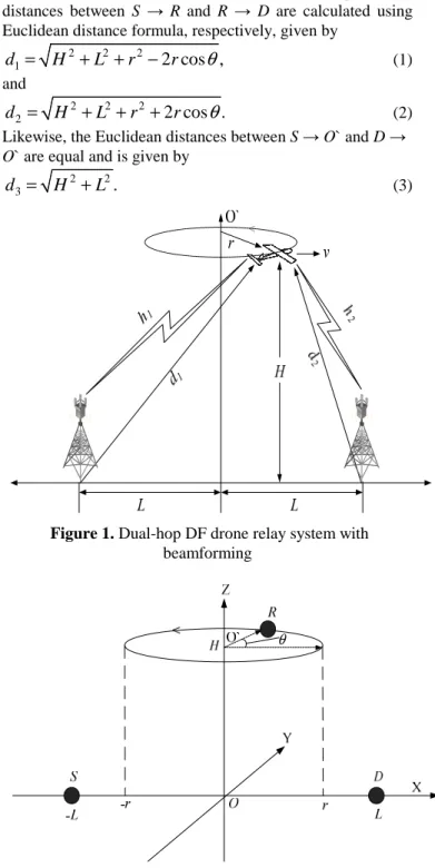
A half-duplex dual-hop wireless communication system consists of a drone DF relay, R, equipped with a single antenna and a stationary source, S, with N1 antennas and a destination, D, with N2 antennas, is considered as depicted in
figure 1. We assume that there is no direct communication link between S and D and data can be delivered only via drone relay R. For the simplicity, we consider the three-dimensional (3D) plane, shown in figure 2. Without loss of generality, we also consider a Cartesian coordinate system with S and D placed at S(-L, 0, 0) and D(L, 0, 0), respectively, i.e., S and D are apart by 2L. It is assumed that the drone R with a moving speed v circles above at an altitude of H > 0 from the ground plane with the origin O`(0, 0, H) as its center point and radius r. Hence, we can say that R is located at R(rcosθ, rsinθ, H), where θ relates to the angle of the circle along which the R flies. In the 3D-plane, the distances between S → R and R → D are calculated using Euclidean distance formula, respectively, given by
2 2 2
1
2 cos ,
d
=
H
+
L
+ −
r
r
θ
(1) and2 2 2
2
2 cos .
d
=
H
+
L
+ +
r
r
θ
(2) Likewise, the Euclidean distances between S → O` and D → O` are equal and is given by2 2
3
.
d
=
H
+
L
(3)Figure 1. Dual-hop DF drone relay system with
beamforming
θ
Figure 2. 3D plane geometry of system model
between S−R and R−D links are assumed to experience independent quasi-static block fading. In the first time period, the source sends data signal x to the relay using N1×1 transmit beamforming, the received signal at the relay is given by [22],
1 1 1 1 1 1
,
T
a
P x
n
=
+
y
h w
(4)where
h
1symbolizes the channel coefficient vector with N1×1 between S and R,a
1is the path loss attenuation factor,P
1represents the source transmit power, (·)T is the transpose operator, n1 is additive white Gaussian noise (AWGN) having mean power PN1, w1 = h1/||h1|| [26], and ||·||F symbolizes the Frobenius norm. In the second time period, the relay decodes the transmitted signal successfully, then re-encodes the data signal
ˆx
and sends the signal with a 1×N2 receive beamforming to the destination. The received signal at D is written as2 2 2 2 2
ˆ
2,
T
a
P x
=
+
y
h w
n
(5)here
h
2designates the channel coefficient vector with 1×N2 between R and D,a
2is the path loss attenuation factor,P
2represents the relay transmit power, n2 is AWGN having mean power PN2, and w2 = h2/||h2|| [26].
The path loss attenuation factors,
a
1anda
2, mentioned in (4) and (5), respectively, anda
3are modeled as [22]1 1
/
1,
2 2/
2, and
3 3/
3,
a
=
K
d
αa
=
K
d
αa
=
K
d
α (6) where K1, K2, and K3 are the constants that depend on environment and α is the path loss exponent. The ratio of received signal power at R during the first time period is expressed as [22](7)
where
H
%
H L
/
andr
%
r L
/
. It is apparent from the figure 2 that r should be less than L for efficient relaying. Similarly, the ratio of received signal power at D during the second time period is written by [22](8)
Throughout this paper, we consider that the total transmit power PT is given by PT = P1 + P2 and the noise power is constant and we set as PN = PN2 = PN1. We define the ratio of the transmit power to the noise power normalized by a3 path loss factor and can be defined as
3. T T N P a P
γ = (9)
Then, using (9), we can determine the received SNRs of the first-hop and second-hop, respectively as
1 1 1( ) 1 T,
γ =β ζ θ wγ (10)
2 2 2( ) 2 T,
γ =β ζ θ w γ (11) whereβ2 P2/PT and thusβ β1+ 2=1. With this normalization, we assume that the total transmission power is fixed relative to noise power for analyzing the system performance.
3.2 Channel Model
In this paper, we model the channel links using the large-scale path loss and κ–μ fading distribution. The large-scale path loss is the degradation in signal strength due to the transmitter and receiver distance [22]. The κ–μ is a generalized fading distribution that can model small-scale fading in line-of-sight (LOS) environments with fading parameters, κ and μ [23]. This fading distribution considers a homogenous environment where a propagating signal composed of clusters of multipath waves. Those clusters assume the scattered waves with same powers, however, each cluster has a dominant component with an arbitrary power. If a link is experiencing a κ–μ fading model, then the PDF expression of an instantaneous SNR
γ
l(
l
=
1, 2)
, with parameters κ and μ, can be expressed as [23], [27]1 1
2 2
1 1
2 2
1
(1 ) (1 )
( ) exp
exp( )
(1 )
2 , (12)
N N N N N f N I N N µ µ
γ µ µ
µ
µ κ γ µ κ γ
γ
γ
κ µ κ γ
κ κ γ
µ γ + − − + − + + = − + ×
l l l l
l l l l l
l l
l l l l
l
l l l l l
l l
l l
l l and its associated CDF is given by
(
)
( ) 1 N 2 , 2 (1 ) / ,
Fγ γ = −Q µ N µ κ µ +κ γ γ
l l l l l l l l l (13)
where
κ
l > 0 designates the ratio of the total power of the dominant component and scattered waves,µ
l > 0 defines the number of multipath clusters,γ
l denotes the average SNR of 1-th hop, Iv (•) is the v-th order modified Bessel function of the first kind, andQ
n( , )
⋅ ⋅
is the generalized Marcum Q-function with n-th order [23].As mentioned earlier, the κ–μ fading distribution includes some particular cases, such as, Nakagami-m (κ→ 0 and μ = m), Rician (κ→ KR and μ = 1), Rayleigh (κ→ 0 and μ = 1), and One-sided Gaussian (κ → 0 and μ = 1/2) distributions, for which m and KR, respectively, represent the Nakagami-m and Rician fading parameters.
4.
Outage Probability
The outage probability can be defined as the probability when the instantaneous end-to-end SNR of a communication link falls below a predefined threshold value
γ
th. Mathematically, it can be given byPr(
γ
<
γ
th)
[7].Here, we derive the outage probability of the proposed system by considering that each communication link follows independent κ–μ fading in conjunction with path loss effect. The probability when the data transmission fails during first time period is given by
(
)
1 1 1
1 1 1 1 1 1
1
1 2 , 2 (1 ) / (14)
Pr(
)
(
)
=
N thth th
Q N
F
µ
γ
µ κ µ κ γ γ
γ γ
γ
− +
<
=
In a similar way, the outage probability during second time period is given by
(
)
2 2 2
2 2 2 2 2 2
2
1 2 , 2 (1 ) / (15)
Pr(
)
(
)
=
N th th th Q N
F
µ γµ κ µ κ γ γ
γ
γ
γ
− +
<
=
(
1)(
2)
( ) 1 1 ( ) 1 ( ) ,
eq
out th th th
P =Fγ γ = − −Fγ γ −Fγ γ (16)
where
1
(
th)
F
γγ
and2
(
th)
F
γγ
are the CDFs of the first-hop and second-hop SNRs, respectively. By substituting (14) and (15) into (16), we get(
)
(
)
1 1
2 2
1 1 1 1 1 1
2 2 2 2 2 2
( ) 1 2 , 2 (1 ) /
2 , 2 (1 ) / . (17)
eq th N th
N th
F Q N
Q N
γ µ
µ
γ µ κ µ κ γ γ
µ κ µ κ γ γ
= − +
× +
5.
Numerical Results and Discussions
In this section, we present the numerical analysis of our proposed system model in terms of the outage probability over κ–μ fading channels. The performance results are obtained with the various configurations of the antennas, N1, N2, distinct values of radius r, and different values of fading parameters, κ and μ. We set the simulation parameters as
H
%
= 0.05, α = 2, K1 = K2 = K3 = 10, and R = 1 bit/sec/Hz. We also provide the Monte Carlo simulations to verify the correctness of the analytical results.
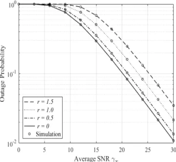
Figure 3 shows the outage performance against average SNR per hop for different values of radius r. It is observed that the outage probability improves with the decrease in r values. In addition, when the radius r = 0, this case shows the performance of rotary-wing drone that can stay at a fixed location.
Figure 3. Outage probability versus average SNR for
different values of r when θ = 90o, κ1 = κ2 = 0.5, μ1 = μ2 = 1, and N1 = N2 = 1
Figure 4 shows the outage performance for various antenna configurations (N1, N2) and different values of radius r as a function of the average SNR per hop. From figure 4, it is seen that the beamforming techniques improve the outage performance remarkably. We see that the significant improvement in outage performance when the number of antennas (N1, N2) increase. Furthermore, the performance gain is enhanced for the respective values of r as the number of antennas is increased.
Figure 4. Outage probability versus average SNR for various
antenna arrangements (N1, N2) and different values of r when
θ = 90o, κ1 = κ2 = 0.5, and μ1 = μ2 = 1
In figure 5, we simulate the outage probability versus average SNR for the particular cases of κ–μ fading models with the different antenna arrangements. Particularly, the S–R and R– D communication links exhibit the independent and identical fading environments such as Rayleigh/Rayleigh, Rician/Rician with parameter KR1 = KR2 = 2, and Nakagami-m/Nakagami-m with parameter m1 = m2 = 2.
Figure 5. Outage probability versus average SNR for
different fading models and with numerous antenna arrangements (N1, N2) when r = 1, θ = 90o, κ1 = κ2 = 0.5, and
μ1 = μ2 = 1
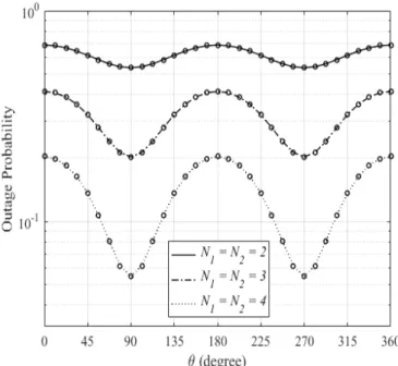
Figure 6. Outage performance versus θ for various arrangements of antenna (N1, N2) when r = 1, γT= 10 dB, κ1
= κ2 = 0.5, and μ1 = μ2 = 1
Figure 7 demonstrates the outage performance with respect to average SNR for the different values of fading parameters,
μ1, μ2, and distinct values of radius r. The results show the substantial enhancements in the outage performance with the increase in the values of μ1, μ2 parameters.
Figure 7. Outage performance versus average SNR for
different values of fading parameters (μ1, μ2) and different values of r when θ = 90o, κ1 = κ2 = 0.5, and N1 = N2 = 2
6.
Conclusions
We proposed a wireless DF relaying network with beamforming for a UAS under κ–μ fading environments, where a fixed-wing drone serves as a moving relay between the source and destination GSs. We derived the closed-form expression for the outage probability of the proposed system. Using that closed-form expression, the system performances for various antenna configurations, several values of radius,
and different values of the fading parameters, are evaluated and compared. The analysis results reveal that the outage performance has a direct relation with the number of antennas (N1, N2) and fading parameters, κ and μ, and has an inverse relation with the radius r.
7.
Acknowledgement
This work was supported by the National Research Foundation of Korea (NRF) grant funded by the Korea government (Ministry of Science, ICT & Future Planning) (No. 2016R1A2B4013118).
References
[1] Y. Zeng, R. Zhang, and T. J. Lim, “Wireless communications with unmanned aerial vehicles: Opportunities and challenges,” IEEE Communication Magazine, Vol. 54, No. 5, pp. 36–42, 2016.
[2] US Department of Transportation, Unmanned aircraft system (UAS) service demand 2015-2035: Literature review & projections of future usage. Tech. Rep., v.0.1, DOT-VNTSC-DoD-13-01, 2013.
[3] T. M. Cover and A. A. El Gamal, “Capacity theorems for the relay channel,” IEEE Transactions Information Theory, Vol. 25, No. 5, pp. 572–584, 1979.
[4] M. O. Hasna and M. S. Alouini,” End-to-end performance of transmission systems with relays over Rayleigh-fading channels,” IEEE Transactions on Wireless Communications, Vol. 2, No. 6, pp. 1126–1131, 2003.
[5] A. Sendonaris, E. Erkip, and B. Aazhang, “User cooperation diversity–Part I: System description,” IEEE Transactions on Communications, Vol. 51, No. 11, pp. 1927–1938, 2003. [6] R. Pabst et al., “Relay-based deployment concepts for wireless
and mobile broadband radio,” IEEE Communications Magazine, Vol. 42, No. 9, pp. 80–89, 2004.
[7] J. N. Laneman, D. N. C. Tse, and G. W. Wornell, “Cooperative diversity in wireless networks: Efficient protocols and outage behavior,” IEEE Transactions on Information Theory, Vol. 50, No. 12, pp. 3062–3080, 2004.
[8] M. I. Hasan and S. Kumar, “Spectral efficiency evaluation for selection combining diversity schemes under worst case of fading scenario,” International Journal of Communication Networks and Information Security (IJCNIS), Vol. 7, No. 3, pp. 123–130, 2015.
[9] M. I. Hasan and S. Kumar, “Average channel capacity evaluation for selection combining diversity schemes over nakagami-0.5 fading channels,” International Journal of Communication Networks and Information Security (IJCNIS), Vol. 7, No. 2, pp. 69–79, 2015.
[10] Y. Zeng, R. Zhang, and T. J. Lim,” Throughput maximization for UAV-enabled mobile relaying systems,” IEEE Transactions on Communication, Vol. 64, No. 12, pp. 4983–4996, 2016. [11] Merwaday and I. Guvenc, “UAV assisted heterogeneous
networks for public safety communications,” In Proc. IEEE Wireless Communication Networking Conference Workshops (WCNCW), New Orleans, LA, USA, pp. 329–334, 2015. [12] S. Jain, K. Fall, and R. Patra, “Routing in a delay tolerant
network,” In Proc. ACM SIGCOMM, Portland, OR, USA, pp. 145–158, 2004.
[13] Z. Zhang, “Routing in intermittently connected mobile ad hoc networks and delay tolerant networks: Overview and challenges,” IEEE Communication Surveys Tutorials, Vol. 8, No. 1, pp. 24–37, 2006.
developments and persisting challenges,” IEEE Communication Surveys Tutorials, Vol. 14, No. 2, pp. 607–640, 2012.
[15] D. H. Choi, S. H. Kim, and D. K. Sung, “Energy-efficient maneuvering and communication of a single UAV-based relay,” IEEE Transactions on Aerospace and Electronic Systems, Vol. 50, No. 3, pp. 2320–2327, 2014.
[16] P. Zhan, K. Yu, and A. L. Swindlehurst, “Wireless relay communications with unmanned aerial vehicles: Performance and optimization,” IEEE Transactions on Aerospace and Electronic Systems, Vol. 47, No. 3, pp. 2068–2085, 2011. [17] F. Jiang and A. L. Swindlehurst,” Optimization of UAV
heading for the ground-to-air uplink,” IEEE Journal on Selected Areas Communication, Vol. 30, No. 5, pp. 99–1005, 2012. [18] Z. Kenan and T. M. Lok, “Optimal power allocation for
relayed transmission through a mobile relay node,” In Proc. IEEE Vehicular Technology Conference (VTC), Taipei, Taiwan, pp. 1–5, 2010.
[19] B. Pearre and T. X. Brown, “Model-free trajectory optimization for wireless data ferries among multiple sources,” In Proc. IEEE Global Communication Conference (GLOBECOM), Miami, FL, USA, pp. 1793–1798, 2010. [20] S. Kim, H. Oh, J. Suk, and A. Tsourdos, “Coordinated
trajectory planning for efficient communication relay using multiple UAVs,” Control Engineering Practical, Vol. 29, pp. 42–49, 2014.
[21] T. A. Johansen, A. Zolich, T. Hansen, and A. J. Sorensen, “Unmanned aerial vehicle as communication relay for autonomous underwater vehicles–field tests,” In Proc. IEEE Global Communication Conference (GLOBECOM), Austin, TX, USA, pp. 1469–1474, 2014.
[22] F. Ono, H. Ochiai, and R. Miura, “A wireless relay network based on unmanned aircraft system with rate optimization,” IEEE Wireless Communication, Vol. 15, No. 11, pp. 7699– 7707, 2016.
[23] M. D. Yacoub, “The η−μ distribution and the κ−μ
distribution,” IEEE Antennas and Propagation Magazine, Vol. 49, No. 1, pp. 68–81, 2007.
[24] A. Hussain, S. H. Kim, and S. H. Chang, “On the performance of dual- hop variable-gain AF relaying with beamforming over
η−µ fading channels," accepted for publication in IEICE
Transactions on Communication (available online at DOI: 10.1587/transcom.2016EBP3279), 2016.
[25] I. Gradshteyn and I. Ryzhik, Table of integrals, series, and products, Academic Press, Boston, 2007.
[26] O. S. Badarneh and R. Mesleh, “Cooperative dual-hop wireless communication systems with beamforming over η−μ fading
channels,” IEEE Transactions on Vehicular Technology, Vol. 65, No. 1, pp. 37–46, 2016.
[27] R. Kumar, A. Aziz, and I. Joe, “Cooperative dual-hop decode-and- forward relaying with beamforming over κ−µ fading