Preprint
of
the
paper
Karan,
B.
“Calibration
of
depth
measurement
model
for
Kinect
‐
type
3D
vision
sensors.”
In
the
21st
International
Conference
in
Central
Europe
on
Computer
Graphics,
Visualization
and
Computer
Vision
WSCG
2013,
Poster
Proceedings,
61
‐
64,
2013.
Published
version
is
available
at
http://otik.zcu.cz/bitstream/handle/11025/10626/Karan.pdf
This
work
is
licensed
under
a
Creative
Commons
‐
Attribution
‐
Noncommercial
‐
No
Derivative
Works
3.0
Serbia
Calibration of Depth Measurement Model for
Kinect-Type 3D Vision Sensors
Branko Karan
Institute of Technical Sciences SASA Belgrade, Serbia
ABSTRACT
Accuracy of depth measurement with Microsoft Kinect and similar 3D vision sensors depends on variations in sensor production. Sensor reading may show significant systematic errors that can be compensated in software by using an adequate depth calibration model. This paper presents one such model and a procedure for identification of its parameters. An example calibration is given to illustrate the procedure and the attained improvements.
Keywords
Kinect, 3D sensing, depth camera, RGB-D camera, camera calibration, depth measurement
1. INTRODUCTION
Since its introduction in 2010, Microsoft Kinect sen-sor gained an enormous popularity in IT community. Prevalent interest has been in its use in computer games and human interface development. Addition-ally, thanks to its mass production and therefore low market price, there is also a growing interest in using this sensor in other fields, such as robotics (e.g., nav-igation, fine manipulation) and general 3D sensing. In emerging fields of applications, accuracy require-ments might be generally stronger than with original-ly envisioned human interfaces. Examples are robot-ics and similar areas where it is of vital importance to investigate and possibly improve sensor accuracy. After initial release of Kinect XBOX 360 in 2010, Microsoft has launched an enhanced version named Kinect for Windows in 2012. At the same time, 3D vision sensors with similar design and capabilities have appeared, such as Asus Xtion and PrimeSense Carmine. Thus, it is possible to speak now about Kinect-type sensors that share similar features, both in terms of advantages and drawbacks.
There have been several works dedicated to improve-ment of accuracy of Kinect-type sensors. Early works, e.g. Burrus [Bur11] and Zhang and Zhang [ZZ11] addressed identification of intrinsic parame-ters of Kinect cameras. Later, focus was also on re-finement of Kinect depth-disparity model, with
im-portant works of Khoshelham and Elberink [KE12], Smisek et al. [SJP11], and Herrera C. et al. [HKH12]. These works addressed transformation of Kinect dis-parity maps into depth maps. However, with new OpenNI [ON13] and Microsoft Kinect SDK [MS13], disparity data are already converted into depth, mak-ing the model considered by these authors obsolete. In this work, an appropriate model for correction of Kinect depth measurements is formulated and a cali-bration procedure is proposed for identification of model parameters. The procedure is simple in the sense that it relies on commonly adopted camera cali-bration tools and it does not require specific calibra-tion objects or external measurement devices. The model and the procedure are described in sections 2 and 3. Results of example calibration are given in Section 4, whereas Section 5 summarizes conclusions on the practical aspects of proposed approach.
2. DEPTH MEASUREMENT MODEL
Operation of Kinect depth sensor is grounded on structured light analysis approach. The sensor (Fig. 1) incorporates a laser IR diode for emitting a dotted light pattern and an IR camera for capturing reflected patterns. By using a suitable window size, the sensor compares reflected patterns to reference patterns, obtained for a plane placed at a known distance from the sensor, and uses the position of the best match pattern to infer disparity of reflected bean and further calculate the depth of reflection surface. A supple-mentary RGB camera is added to provide additional information on color and texture of the surface. The relationship between depth of reflection surface and the disparity between images of light beans ob-tained for a reference and measurement (object) sur-face may be derived in the following manner (the derivation closely follows Khoshelham and Elberink
Permission to make digital or hard copies of all or part of this work for personal or classroom use is granted without fee provided that copies are not made or distributed for profit or commercial advantage and that copies bear this notice and the full citation on the first page. To copy otherwise, or republish, to post on servers or to redistribute to lists, requires prior specific permission and/or a fee.
[KE12]). Looking at Fig. 1, where the reference bean is assumed to pass the path P R C and the meas-urement bean passes the path P M C , from simi-larity of trianglesMR C and M R C we obtain:
d f
D Z (1)
where Z is the distance of the measurement (object) plane from the sensor, d R M denotes the dispar-ity between images of reference R and
measure-ment M beans, and f is the focal length of IR
camera. From similarity of triangles CPR and
R MR , another relation is obtained:
0 0 Z Z D b Z (2)
in which Z0 denotes the distance of the reference
plane from the sensor. By eliminating D from (1) and (2), the depth measurement model is obtained in the form:
0
1 1 d
Z Z bf (3)
The model (3) is internally used by sensor software to transform detected disparity into depth. However, the value of inferred depth depends on values b f Z, , 0
that are subject to manufacturing variations. Thus, the actual output ZS from the sensor is really an
ap-proximation based on the nominal model:
0
1 1
S N N N
d
Z Z b f (4)
By combining (3) and (4), the following relationship between Z and ZSis obtained:
1 1
Z Z
S
a b
Z Z (5)
where a bZ, Z are the values that are characteristics of
particular sensor: 0 0 1 1 ; N N Z Z Z N b f a b a bf Z Z
Ideally, aZ 1,bZ0. However, for a specific sen-sor, depth model parameters a bZ, Z may differ from
ideal values and this difference may produce signifi-cant systematic errors in depth measurement. There-fore, appropriate tuning of depth model parameters may result in improved measurement accuracy.
3. CALIBRATION PROCEDURE
The proposed calibration procedure consists of two steps: the first step comprises standard calibration of sensor’s RGB/IR cameras, whereas the calibration of depth model is performed within the second step.
Camera calibration
Camera calibration assumes identification of param-eters of functions modeling transformation of coordi-nates of external objects into coordicoordi-nates of their images. For a point with homogeneous coordinates
, , ,1
Te X Y Ze e e
X in some external world
coordi-nate frame, transformation of coordicoordi-nates involves (a) transformation X T X e e into coordinates in
camera frame, (b) projection Z x
I 0 X
into the point x
u v, ,1
T in normalized image plane, (c) dis-tortion x( )d f( )d ( )x , yielding distorted normalizedcoordinates x( )d , and finally (d) transformation into
pixel coordinates x( )p , using transformation of the
form x( )p K x( )d . Thus, calibration consists in
identification of camera matrix K, distortion func-tion f( )d ( ) and transformation matrix
e T .
Calibration of Kinect RGB/IR cameras follows a standard procedure of stereo camera calibration whose details is out of scope of this paper. It consists in essence in collecting pairs of images of different views of certain calibration object (e.g., a plane with a checkerboard texture) with known local 3D coordi-nates of specific feature points (e.g., checkerboard corners). The process proceeds by extracting 2D age coordinates of feature points from individual im-ages and then by performing optimization to find the optimum transformations for all pairs of 3D/2D coor-dinates of all feature points in all views. The result is obtained in the form of camera matricesKRGB,KIR,
distortion functions ( )d ( ) RGB
f , ( )d ( ) IR
f , and homogene-ous transformation matrix IR
RGB T for transformation Z0 D d f b M M' R'' R' C P R Z reference plane measurement plane image plane IR camera IR projector
of homogeneous 3D coordinates from RGB to IR camera frame.
To achieve appropriate light conditions for calibra-tion of IR camera, IR emitter has to be disabled dur-ing imagdur-ing (in this work, the older XBOX 360 was used, so the projector was simply covered by an ordi-nary stick tape; the newer model Kinect for Windows allows programmable control over the IR emitter). Good calibration of both RGB/IR cameras is essen-tial part of the procedure, because cameras are used as measurement devices for the second calibration step.
Depth model calibration
During the second step, a series of images is again collected, with each image containing a view to the calibration checkerboard plane placed in different positions and orientations w.r.t. the sensor. However, instead of pairs of RGB/IR images, this time the IR emitter of the sensor is left enabled and a set of pairs of RGB/depth images is collected.
As in the first step, checkerboard corners are used as calibration feature points with known local coordi-nates in checkerboard frame, which can be expressed as XC( , ) ( 1) , (i j
i w j 1) , 0,1h
T, where w h, is the width/height of checkerboard fields. For each view k, the acquired RGB image is transformed into a grayscale image from which 2D pixel coordinates( )p ( , , ) RGB i j k
x of all checkerboard corners are extracted and paired to known external coordinates XC( , )i j to calculate the checkerboard pose RGB ( )
C k
T . Using the
known transformation between camera frames, cor-ner coordinates are expressed in IR camera frame as:
( , , ) IR RGB ( , )
IR i j k RGB C C i j
X T T X
Thez-component ( , , )Z i j k of such an obtained posi-tion is afterward compared to sensor reading. The sensor value is determined by converting XIR( , , )i j k into pixel coordinates and by searching for the nearest neighbor in sensor depth map mk:
( ) ( ) ( ) ( , , ) ( , , ) ( , , ) ( , , ) ( ( , , )) ( , , ) (round( ( , , ))) IR IR p d IR IR IR IR p S k IR i j k i j k Z i j k i j k f i j k Z i j k m i j k x I 0 X x K x xFinally, the obtained set of pairs Z i j k( , , ) and ( , , )
S
Z i j k is employed to fit the parameters a bZ, Z of
depth calibration model (5).
4. CALIBRATION EXAMPLE
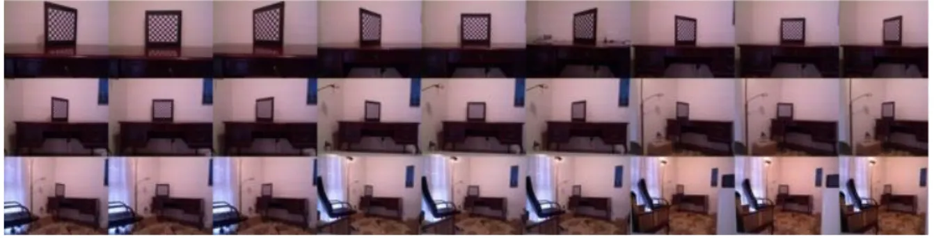
An experiment has been made to calibrate Kinect us-ing a simple 9 8 checkerboard with 30mm square fields. First, a set of close-up views of the checker-board placed in different orientations was employed to identify camera parameters. Afterward, for the sec-ond phase, a set of 27 RGB/depth image pairs as shown in Figure 2 was prepared. The images were di-vided in 9 groups, each containing three RGB/depth images of the calibration table placed approximately at the same distance from Kinect but in different ori-entations. To increase precision, all images were made with the highest resolution of Kinect cameras: 1280x960 for the RGB and 640x480 for the IR camera. For each image acquired by the RGB cam-era, corner coordinates were then extracted for inner 10 9 corners. In this manner, 9 point clusters, each containing 270 points were generated. The extracted coordinates were used to calculate orientation and position of the table and further to find 3D coordi-nates of all corners. The values of depth obtained from RGB images are finally compared to depth val-ues obtained from Kinect. The differences are shown in Figure 3, where the points corresponding to partic-ular clusters are displayed in different colors.
It is readily seen that both average values of errors and error deviations obtained from Kinect measure-ments increase with distance. Moreover, the averages show strong regularity that is in accordance to depth measurement model (5).
Using all collected points, parameters of the depth measurement model were computed by least square fitting as aZ 0.9968, bZ4.3651 10 6 . The
corre-sponding correction curve is also shown in Figure 3.
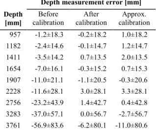
Table 1 summarizes statistics on errors obtained be-fore and after correction of depth measurement. It is seen that average values dramatically decreased. Av-erage errors, which were in the range from 1mm for 1m distance (relative error of 0.1%) to 57mm on dis-tance of 3.7m (relative error of 1.5%), practically di-minished after calibration, that is, they have been re-duced to a level of precision attainable by calibrated
RGB camera. On the other side, as expected, con-fidence intervals (the values in Table 1 are empiric
3 intervals) underwent only slight changes. Good matching between experimentally obtained av-erage errors and values predicted by the model offers a possibility to significantly reduce number of cali-bration measurements. Since the model (5) has only two parameters, it may be expected that similar re-sults could be obtained by using only two clusters of points. Indeed, by selecting clusters 5 and 7, parame-ters are obtained as aZ0.9989,bZ 3.4618 10 6.
The corresponding statistics calculated for all data points is shown in the last column of Table 1.
5. CONCLUSION
This paper has demonstrated that calibration of Ki-nect depth sensor can be achieved using the same calibration tools that are commonly used in ordinary camera calibration. Moreover, it has been shown that it is enough to perform calibration imaging at only two distances in the expected range of operation. It is important to underline that the error reduction demonstrated in this paper is indeed a reduction of differences between reading of Kinect depth sensor and depth values obtained using Kinect RGB camera. Therefore, well calibrated camera is a prerequisite for a quality calibration.
6. ACKNOWLEDGMENTS
This work was supported in part by the Serbian Min-istry of Education, Science and Technology Devel-opment under grants III-44008 and TR-35003. All the analysis conducted in this work has been per-formed in Matlab environment, using Bouguet’s Camera Calibration Toolbox [Bou10].
7. REFERENCES
[Bou10] Bouguet, J. Camera Calibration Toolbox for Matlab. http://www.vision.caltech.edu/bouguetj/-calib_doc/ (last modified 09.07.2010)
[Bur11] Burrus, N. Kinect calibration. http://nicolas.-
burrus.name/index.php/Research/Kinect-Calibration (last modified 07.08.2011)
[HKH12] Herrera C., D., Kannala, J., and Heikkilä, J. Joint depth and color camera calibration with dis-tortion correction. IEEE Trans. Pattern Analysis and Machine Intelligence, Vol. 34, pp. 2058– 2064, 2012.
[KE12] Khoshelham, K. and Elberink, S.O. Accuracy and resolution of Kinect depth data for indoor mapping applications. Sensors, Vol. 12, pp. 1437–1454, 2012.
[MS13] Microsoft Corporation. Kinect for Windows SDK. http://msdn.microsoft.com/en-us/library/-hh855347.aspx (accessed 27.03.2013)
[ON13] OpenNI Consortium. OpenNI, the standard framework for 3D sensing, http://www.openni.-org/ (accessed 27.03.2013)
[SJP11] Smisek, J. Jancosek, M., and Pajdla, T. 3D with Kinect. Proc. IEEE Int. Conf. Computer Vision Workshops, Barcelona, Spain, pp. 1154– 1160, 2011.
[ZZ11] Zhang, C. and Zhang, Z. Calibration between depth and color sensors for commodity depth cameras. 2011 IEEE Int. Conf. Multimedia and Expo (ICME), pp. 1-6, 2011.
Depth [mm]
Depth measurement error [mm]
Before
calibration calibrationAfter calibrationApprox.
957 -1.2±18.3 -0.2±18.2 1.0±18.2 1182 -2.4±14.6 -0.1±14.7 1.2±14.7 1411 -3.5±14.2 0.7±13.5 2.0±13.5 1654 -7.0±16.1 -0.3±15.2 0.7±15.3 1907 -11.0±21.1 -1.1±20.5 -0.3±20.6 2228 -11.6±28.1 3.0±28.1 3.3±28.1 2756 -23.2±43.9 1.4±42.7 0.4±42.8 3283 -37.0±57.1 0.0±56.7 -2.7±56.7 3761 -56.9±83.6 -6.2±80.1 -11.0±80.6
Table 1. Improvement in depth measurement Figure 3. Depth measurement error
0 1000 2000 3000 4000 -150 -125 -100 -75 -50 -25 0 25 50 Depth [mm] D ep th m ea su re m en t e rro r [m m ]