Online Tuning Based Fuzzy Logic Controller
for Speed Control of BLDC Motor
George Jacob
1, Tony AbyVarkey M
2, PriyankaMukesh
3, Jisha K. R.
4U. G. Student, Dept of AEI, AdiShankara Institute of Engg. And Tech., Kalady, Kerala, India1 Assistant Professor, Dept of ECE, Faculty of Engineering, Christ University, Bangalore, India2 Assistant Profess or, Dept of AEI, AdiShankara Institute of Engg. And Tech., Kalady, Kerala, India3
Assistant Professor, Dept of AEI, AdiShankara Institute of Engg. And Tech., Kalady, Kerala, India4
ABSTRACT: Brushless Direct Current (BLDC) motors are one of the motor types rapidly gaining popularity. BLDC motors are widely used in industries such as Appliances, Automotive, Aerospace, Consumer, Medical, Industrial Automation Equipment and Instrumentation. BLDC motors are receiving wide attention due to their high efficiency, high dynamic response, better speed versus torque characteristics and small size. Conventional controllers are widely used to control BLDC motors. But they often fail to control the BLDC as they suffer from uncertain parameters and the non-linearity of the BLDC motors. Fuzzy control can be used to control the speed of the BLDC motors. In this paper, a fuzzy logic controller whose parameters are tuned on line is proposed to control the speed of a BLDC motor and is compared with conventional controllers like PI and PID.
KEYWORDS: BLDC, FLC, PI, PID
I. INTRODUCTION
Brushless DC motors are reliable, easy to control and inexpensive. Due to their favorable electrical and mechanical properties, high starting torque and high efficiency, the BLDC motors are widely used in most servo application as actuation, robotics, machine tools and so on. The design of the BLDCM servo system usually requires time consuming trial and error process, and fail to optimize the performance. In practice, the design of the BLDCM drive involves a complex process such as model, devise of control scheme, simulation and parameters tuning. Usually, the parameters tuning for a servo system involves a sophisticated and tedious process and requires an experienced engineer in doing so. The PI controller is suitable for the linear motor control. However, in practice, the driver and load impose many non-linear factors. The PI controller cannot be suitable for non-non-linear system. Fuzzy control is a versatile and effective approach to deal with the linear and uncertain system. Even if a fuzzy controller (FLC) can produce arbitrary non-linear control law, the lack of systematic procedure for the configuration of its parameters remains the main obstacle in practical applications.
II. BLDC MOTORS
A. Modeling of PMBLDC Motor
The state space model of a PM Brushless Dc motor is developed as
NBlr
P
where
Rs = stator resistance per phase
L = stator inductance per phase M = mutual inductance.
ias, ibs, ics are the stator phase currents m is the electrical rotor speed r is the electrical rotor position
N is the number of conductors in series per phase B is the flux density of the field
L is the rotor length R is the rotor radius
fas, fbs, fcs are functions of rotor electrical position.
J is the moment of inertia P is the number of poles
vasvbsvcs are the individual phase voltages
T
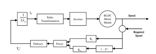
III.CONTROLDIAGRAM
Fig. 3.1.Control Diagram for speed control of BLDC Motor
IV.TORQUEDEVELOPED
The electromagnetic torque developed is given by
The instantaneuous induced emfs can be written as
Substituting the values of back emfs in the equation for torque, we get
Only two machine phases conduct current at any time, with the two phases being in series for full wave inverter operation, so the phase currents are equal in magnitude but opposite in sign. The rotor position dependent functions have the same signs as the stator phase currents in the motoring mode, but opposite signs in the regeneration mode. The result of such sign relationships is simplification of torque command as,
V. VECTOR CONTROL
The vector control of the PMBLDC motor is derived from its dynamic model. Considering the currents as the inputs, the three phase currents are
Where is the electrical rotor speed and is the angle between the rotor field and the stator phasor, known as the BLDC
Motor Model
Ke
1 –Z-1
Kec
Fuzzy Defuzzy
Parks Transformation
Te*
ip
Inverter
Speed
Required Speed
p
2
1 BLDC
Motor Model
Ke
1 –Z-1
Kec
Fuzzy Defuzzy
Parks Transformation
Te*
ip
Inverter
Speed
Required Speed
p
2
1 BLDC
Motor Model
Ke
1 –Z-1
Kec
Fuzzy Defuzzy
Parks Transformation
Te*
ip
Inverter
Speed
Required Speed
p
2 1
m cs cs bs bs as as
e
e
i
e
i
e
i
T
1
]
[
m p r cs cs
m p r bs bs
m p r as as
f
e
f
e
f
e
)
(
)
(
)
(
]
)
(
)
(
)
(
[
as r as bs r bs cs r csp
e
f
i
f
i
f
i
T
)
3
2
sin(
)
3
2
sin(
)
sin(
t
i
i
t
i
i
t
i
i
r s as
r s bs
r s as
*
2
p pe
i
The rotor field is traveling at a speed of r rad/sec; hence the q and d axes stator currents in the rotor reference frame
for a balanced three – phase operation are given by
cs bs as r r r r r r r ds r qsi
i
i
t
t
t
t
t
t
i
i
3
2
sin
3
2
sin
sin
3
2
cos
3
2
cos
cos
3
2
From the above equations, the stator currents in the rotor reference frames:
cos
sin
s r ds r qsi
i
i
The stator – phase current commands are obtained for a balanced three phase operation as
These stator – phase current commands are amplified by the inverter and its logic and fed to the PMBLDC. VI. FUZZY CONTROL
Fuzzy logic provides an approximate effective mean of describing the behavior of some complex system. Unlike traditional logic type, fuzzy logic aims to model the imprecise modes of human reasoning and decision making, which are essential to our ability to make rational decisions in situations of uncertainty and imprecision.
The most significant variables entering the fuzzy logic speed controller have been selected as the speed error (e) and its time derivative (ec). The output this controller is U. The two input variables e(speed error) and ec(change in error) are calculated at each sampling time as
where s*(k) is the reference speed at that time and s(k) is the actual speed. The FLC consists of three stages:
1. Fuzzy
2. Rule execution and 3. Defuzzification.
A. Fuzzy Operation:
In this stage the crisp variables are converted in to fuzzy variables as:
u f
ec f
e f
K
u
u
ec
K
ec
e
K
e
/
whereKe and Kec are the proportion coefficients which transform the input to the universe of fuzzy sets. Ku transform the fuzzy output to the actual control value. All these transformations are strictly according to the prescribed membership functions associated with the input and output variables. The membership function has been chosen to be triangular as shown in figure.
Figure 6.1. : Membership Functions
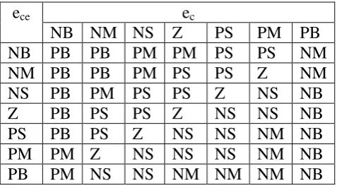
B. Rule Execution
The universe of discourse of input variables error (e) and change in error (ec)and output U are divided from –0.6 to +0.6. Each universe of discourse is divided into seven fuzzy sets: NB, NM, NS, Z, PS, PM and PB. Each fuzzy variable is a member of the subsets with a degree of between 0 (non member) and 1(full member) as
A
A
x
A A
A
,
0
,
1
)
(
The variables error (ec) and change in error (ece) are processed by an inference engine which executes 49 rules.
All the 49 rules are given in the table 1. Each rule is expressed in the form as If ec is NB and ece is Z then U is PB
If ec is NS and eceis NM then U is PM ……. and so on
e
cee
cNB NM NS Z
PS
PM PB
NB PB PB
PM PM PS
PS
NM
NM PB PB
PM PS
PS
Z
NM
NS
PB PM PS
PS
Z
NS
NB
Z
PB PS
PS
Z
NS
NS
NB
PS
PB PS
Z
NS
NS
NM NB
PM PM Z
NS NS
NS
NM NB
PB
PM NS
NS NM NM NM NB
to resolve a single output value from the set. The most popular defuzzification method is the centroid calculation, which returns the center of area under the curve is used here. The centroid of each output membership function for each rule is first evaluated. The final output is then calculated as the average of the individual centroid.
VII. ON-LINE TUNING
In order to improve the dynamic performance of the BLDCM servo system, the elements ofthe query table need to be adjusted according to the input variables. To do this, this paper adjuststhe coefficients (Ke, Kecand Ku) to tuning the
control system on-line.
The basic principle is the “rough adjustment” and “accurate adjustment”, namely, constantlyadjusting the
coefficients according to actual error and change in error. If the errorand change in errorare large, KeandKec should be
reduced while Ku should be increased because the main objective is diminishingthe errors. When error and change in
errorare small, because the main aim is to diminish the overshoot andsteady-state error, Ke and Kec should be increased
to increase the resolution of errorand change in errorwhile Kushould be reduced to obtain small control value to reduce
the overshoot andsteady-state error. The adjust functions as follows:
VIII. RESULTS
The proposed Fuzzy Logic Controller is compared with conventional controllers like the PI and the PID controller for evaluating the validity of the Fuzzy Logic Controller developed. Figure 8.1 shows the response of the system when a PI controller is used. Figure 8.2 shows the response when a PID controller is used. Figure 8.3 shows the response when the proposed Fuzzy Logic Controller is used.
,
2
,
,
2
,
,
2
,
max 1 0
1 0
max 1 0
1 0
max 1 0
1 0
e
K
K
e
K
K
K
e
K
K
e
K
K
K
e
K
K
e
K
K
K
u u u
ec ec ec
e e e
2 2 2 2 2 2
max max max max max max
e e
e e
e e
e e
e e
e e
Figure8.1: Control using PI Controller
Figure8.2: Control using PID Controller
Figure 8.3: Control using Fuzzy Logic
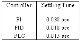
Figure 8.1 shows that the PI controller has a larger overshoot. Figure 8.2 shows that the PID controller does not meet the required speed specifications. The response of the Fuzzy Logic Controller shown in figure 8.3 has a much lesser overshoot and a very good steady state response. The value of the settling time for 2% tolerance for the three controllers are provided in the table 8.1.
IX. CONCLUSION
The work consisted of comparing the control strategies available to control the BLDC motor. PI and PID controller fail to meet the performance specifications as both these conventional controllers does not provide a good solution for non linear systems. The Fuzzy Logic Controller offers a very good solution to control the speed of the BLDC motor as FLC are mainly used for non linear or uncertain systems.
REFERENCES [1] R. Krishnan, “Electric Motor Drives Modeling Analysis and Control” Pearson Education
[2] W.S. Oh, Y.T. Kim, C.-S. Kim, T.S. Kown, and H.J. Kim, “Speed Control of Induction Motor Using Genetic Algorithm Based Fuzzy Controller,”
Industrial Electronics Society Conference of IEEE, vol. 3, no. 2, pp. 625-629, 1999
[3]D. Silva, W. Acarnley, and Finch, “Application of Genetic Algorithm to the Online Tuning of Electric Drive Speed Controllers,” Trans. Ind. Electron of IEEE, vol. 47, no. 1, pp. 217-219, 2000.
[4] www.microchip.com
[5] Takagi T. and Sugeno M., “Fuzzy Identification of Systems and Its Applications to Modeling and Control”, IEEE Transactions on Systems, Man, and Cybernetics, 15, 1, 116-132, 1985