Active Vibration Attenuation for Uncertain
Buildings Structural Systems with Sensor Faults
Yuanchun Ding
School of Resources and Environmental Engineering, Jiangxi University of Science and Technology, Ganzhou, Jiangxi, 341000, China;
E-mail: [email protected]
Falu Weng* and Liming Liang
Faculty of Electrical Engineering and Automation, Jiangxi University of Science and Technology, Ganzhou, Jiangxi, 341000, China.
E-mail: [email protected]; [email protected]
Abstract—The problem of sensor fault-tolerant vibration-attenuation controller design for uncertain buildings structural systems is investigated in this paper. The objective of designing controllers is to guarantee the asymptotic stability of closed-loop systems while attenuate disturbance from earthquake excitation. Firstly, based on matrix transformation, the structural system is described as a state-space model, which contains sensor faults and parameter uncertainties. Based on the obtained model, the LMIs-based conditions for the system to be stabilizable are deduced. By solving these LMIs, the controllers are established for the closed-loop system to be stable with a prescribed level of disturbance attenuation and sensor fault-tolerant. Finally, an example is included to demonstrate the effectiveness of the proposed theorems.
Index Terms—robust control; sensor fault; structural system; vibration; LMI
I. INTRODUCTION
Nowadays, because tsunamis and earthquake, such as 2008 Wen Chuan earthquake etc., happen frequently, vibration control for buildings structural system has received considerable attention. Some vibration control methods, such as passive control, semi-active control and active control were proposed for attenuating those external disturbances. Compared with the other two control methods, active control has many virtues, such as continuous force control and broad-band control frequency etc. Therefore, research on the active vibration control of buildings structural system has received increasing attention in the recent years [1]. Many scholars applied themselves to the research of active vibration control strategies and many control techniques have been achieved, such as, classical H theories [2,3] , Finite frequency H control [4], sliding mode control [5,6],
adaptive control[7], neural networks [8], fuzzy control [9], optimal control [10], bang-bang control [11,12], etc., have been developed with the goal of protecting structures subjected to external disturbance excitation. Accompanied with the development of structural control strategies, some active control devices were designed for applying those control algorithms, for example, active brace system (ABS) [13, 14], active mass damper (AMD) [15], etc. have been widely studied and used for vibration attenuation.
On the other hand, much effort has been devoted to the fault tolerant control or reliable control during the past decades because unexpected faults or failures may result in substantial damage, and can even be hazardous to human and environmental security [16, 17]. As we all known that the structural control systems have some characters, such as, long working hours, harsh working environment, etc.. Thus, a high degree of fault tolerance for the structural control systems is an essential and integrated part of the overall control system design. In recent years, the problem of fault tolerant control in buildings structural systems has received considerable attention and various techniques have been developed. For example, by adopting a DC-motor based active mass driving device, [18] investigated fault tolerant control system design for structure based on two experiments. Ref. [19] presented a direct adaptive fault-tolerant neural control scheme for the nonlinear hysteretic base-isolated buildings by using the recently developed extended minimal resource allocation network (EMRAN). Based on LMI technique, [20] dealt with the problem of robustly reliable energy-to-peak controller design for seismic-excited buildings with actuator faults and parameter uncertainties. However, to the best of the authors’ knowledge, the sensor fault-tolerant vibration-attenuation controller design for uncertain linear structural systems is still not fully investigated.
This paper is concerned with the problem of sensor fault-tolerant vibration-attenuation controller design for uncertain buildings structural systems. Based on matrix transformation, a state-space model of buildings structure
Manuscript received April 4, 2013; revised May 7, 2013; accepted May 19, 2013.
with parameter uncertainties and sensor faults is firstly established. Then, based on Lyapunov stability theory, the LMIs-based conditions for the system to be stabilizable are deduced. By solving these LMIs, the controllers against sensor faults are established for the closed-loop system to be stable with the performance
2
z t t . Finally, simulation results show that the proposed controllers are effective for vibration attenuation of the structural systems with sensor faults.
The organization of this paper is as follows. Section 2 formulates the problem and presents the dynamic models. The main results are given in section 3. The illustrative examples are given in section 4 to show the applicability and improvement of the presented approaches. Finally, the paper is concluded in section 5.
Notation: Throughout this paper, for real matrices X
and Y, the notation X Y (respectively, X Y ) means that the matrix XY is semi-positive definite (respectively, positive definite). I is the identity matrix with appropriate dimension, and a superscript “T” represents transpose. For a symmetric matrix, * denotes
the symmetric terms. The symbol n
R stands for then -dimensional Euclidean space, and n m
R is the set of n m real matrices
II. PROBLEM FORMULATION AND DYNAMIC MODELS
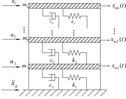
Consider an n degree-of-freedom structural system, which is depicted in Figure 1. The linear structural model equation can be written with [2, 19-23]
g
x
1
m
2
m
1
c
2
c
1
k
2
k
2( )
m
x t
n
m
n
c kn
( )
mn x t
1( )
m x t
1
u
2
u
n
u
Figure 1. n degree-of-freedom structural system.
0
( ) ( ) ( ) ( ) ( )
m m m g
Mx t Cx t Kx t H u t H x t , (1)
where x tm( )
xm1( ),t xm2( ),t ,xmn( )t
T , xmn( )t is the relative displacement of the thn storey to ground; ( )u t is the control force input;x tg( )is the ground acceleration caused by earthquakes; n mHR gives the locations of these controllers; n1
HR is an vector denoting the influence of disturbance excitation; and , , n n
M C KR
are the mass, damping and stiffness matrices of the system, respectively.
Defining the state variables as ( )x t x tm( ) ,T x tm( )TT, the system (1) can be written in the following state-space form:
( ) ( ) ( ) ( ), ( ) z ( ),
x t Ax t Bu t B t z t C x t
(2)
where Cz is real constant matrix with appropriate
dimensions, and
1 1
0 I
A
M K M C
, 1
0 B
M H
, 1
0 B
M H
,
( )t x tg( )
.
According to [20], we can know that the damping and stiffness of buildings cannot be measured easily and precisely, while the mass of buildings can be measured precisely. Thus parameter uncertainties in buildings structural systems mainly locate in matrix A . We takeAto represent the system uncertainties with the same dimensions as that ofA. Similar to [20], A is assumed to be norm-bounded, that is
A
. (3)
Therefore, the building vibration control system with parameter uncertainties can be described as
( ) ( ) ( ) ( ),
( ) z ( ).
x t A A x t Bu t B t z t C x t
(4)
When considering the possible sensor faults, we introduce a state-feedback controller in the form of
( ) ( )
u t F t x t , (5) whereFis the sensor fault-tolerant controller gain to be design later. Sensor faults are described by fault matrix
t diag
1
t ,2
t ,2n
t
, where i
i t i
. i andi represent the lower and upper
bounds ofi
t , respectively. If i i 1, there is nofailure in the thi sensor. Wheni i 0, the thi sensor is completely broke down. By denoting
ˆi i i 2
. ˆi
t 1i
t ˆi, 1i
t 1i,
1i i i i i
, i1, 2,, 2n,
the sensor fault matrix
t can be expressed as
t ˆ ˆ
t , (6)
where
1 2 2
ˆ diag ˆ t , ˆ t , , ˆ n t
,
2
1 1
ˆ n ˆ T
i i i i i
t t e e
i
eis a column vector with the ithitem to be 1 and others to be 0.
We assume that the disturbance
t is bounded with finite energy, that is,
22 t 0
t t dt
. (7)According to [20], we can obtain that (7) is a reasonable assumption, which can be satisfied by most earthquakes. We assume that the peak response quantity of the controlled output satisfies
0,
sup T
t
z t z t z t
. (8)
The focus of this paper is to find a feasible method for designing a state feedback controlleru t( )F
t x t( ) and seeking the corresponding controller gainF, which guarantees asymptotical stability of the obtained closed-loop system and the performance
2
z t t for all non-zero
t given by (7) and the prescribed constant 0.Lemma 1 [21]: given matrices , and with
appropriate dimensions and with symmetrical, then
( ) T ( )T T 0
F t F t
(9)
holds for anyF t( )satisfying ( )T ( )
F t F t I , if and only if there exists a scalar0such that
1
0
T T
. (10)
Ⅲ. MAIN RESULTS
Theorem 1: The system (2) is asymptotically stabilizable with
2
z t t for all non-zero
t given by (7), and constant 0 , if there exist positive definite symmetric matrix P , matrixQ , and positive scalars1, 2, , 2n
v v v satisfying the following LMIs
11 13
1
33
0 0
B I
, (11)
2 2 0
T z P PC
, (12)
where
2 2
11 1
1
ˆ ˆ
n
T T T T
i i i i i
AP BQ PA Q B v
,
13 1, 2, 2n
, i e Q BiT T T 0T,
0 T
T i ei
, 33 diag
v1, v2,,v2n
.Furthermore, a state-feedback controller is described as
1
FQP .
Proof: Bysubstituting the control lawu t( )F
t x t( ) into system (2) , we can obtain the following closed-loop system
( ) ( ) ( ),
( ) z ( ).
x t A BF t x t B t z t C x t
(13)
Choose a Lyapunov-Krasovskii functional candidate as
( )T ( )V t x t Px t . (14)
The derivative of V t( )along the solution of system (13) is given by
0
( ) 2 ( ) ( )
2 ( ) ( ) ( ) .
T
T V t x t Px t
x t P A BF t x t B t
(15)
Assume zero initial condition, i.e. x t( ) t00 and
0
( ) t 0
V t . Consider the index
0
( ) t ( )T ( )
JV t
s s ds . (16)Then, for any non-zero
t given by (7), there holds
0 0
0
0
( ) ( ) ( ) ( )
( ) ( ) ( )
,
t T t
t
T
t T
J V t V t s s ds
V s s s ds
s s ds
where
, ( )T
T T
s x s s
and
T
T TPA PBF t A P t F B P PB I
.
Assume the zero disturbance input, i.e.( )t 0. If 0
, we can easily obtainV t( )0, and the asymptotic stabilizability of system (2) is established. By pre- and post-multiplying 0 with diag P
1,I
and its transpose respectively, and defining 1PP , we obtain 0is equal to
0
T T T
AP BF t P PA P t F B B
I
.
(17)
By considering that
t P
t P
T, and definingQFP, we can obtain 0is equal to
T
T T 0AP BQ t PA t Q B B
I
. (18)
2 2 1 1 1 1 ˆ ˆ 0.0 0 0 0
T T T
T T
n n
i i i i
i i
i i
AP BQ PA Q B B
I
BQe e e BQe
t t
Then, according to the Schur compliment and lemma 1, we can obtain 0from (11). ThusJ0, and therefore, the following inequality holds:
0
( )T ( ) t T
x t Px t V t
s s ds.Furthermore, according to (12), we can obtain the following equation 2 0 z P C .
Then, it is easy to obtain
2
2
0 .
T T T T
z z
t T
z t z t x t C C x t x t Px t s s ds
Taking the supremum over t0 yields z t
2
2 22
t
for all non-zero
t given by (7). This completes the proof.Theorem 2: The system (4) is robustly stabilizable with
2z t t for all non-zero
t given by (7), and constant 0 , if there exist positive definite symmetric matrix P , matrix Q , positive scalars1, 2, , 2n
v v v and satisfying (12) and the following LMI
1 14 0
* T I
, (19)
where
0
, 14
0
T T
I P
. Furthermore, a
state-feedback controller is described as 1
FQP .
Proof: ReplacingAwithA A, (11) can be expressed as
1
0 0
0.
0 0 0 0
T
AP AP
(20)
By Lemma 1, (20) holds if and only if there exist a positive scalarsuch that
1
1 0.
0 0 0 0
T T
A A P P
(21)
According to (3), we can obtain (21) from the following (22).
1
1 0.
0 0
T P P
(22)
Applying the Schur complement, LMI (22) is equivalent to LMI (19). This completes the proof.
Ⅳ. ILLUSTRATIVE EXAMPLE
Consider the structural system with n3 . The structural parameters aremi 1000kg ,ki 980kN m/ , andci 1.407kNs m/
i1, 2, 3
. Then the state space equation (2) has the following parameters [19]:1 2 3 0 0 0 0 0 0 m M m m ,
1 2 2
2 2 3 3
3 3
0
,
0
k k k
K k k k k
k k
1 2 2
2 2 3 3
3 3
0
0
c c c
C c c c c
c c , 1 1 1 T H , 1 2 3 T m H m m ,
1 2 3 1 2 3
T x x x x x x x .
Assume that the displacements and velocities of the three storeys are all measurable for feedback in this case. The controlled output is chosen to be the relative displacements of each storey, that is,
1
2
3
T
m m m
z t x t x t x t .
Firstly, consider the system without sensor faults, that isi i 1. By solving the LMIs (11)-(12) with
0.4
, we obtain a state feedback controller which has the following gain matrix
446.89 980.57 0.6039 59.334 980.64 446.89 980.6 1.4434 0.5989 980.6 533.1 0.0343 1.4395 0.0346
59.334 1.4414 . 1.4415 60.74 F (23)
For description in brevity, we denote this designed controller as controller I thereafter.
Consider the system with sensor faults. By supposing that i 0.1, i 1.3, where i1, 2, 3, 4, 5, 6, we can
obtain
ˆ diag 0.7, 0.7, 0.7, 0.7, 0.7, 0.7
,
6
1
ˆ 0.7 T
i i i i
t t e e
,
1.2, 1, 2, 3, 3, 4, 5, 6, 1.4
i t i
e1
1 0 0 0 0 0
T,
2 0 1 0 0 0 0
T
e , 3
0 0 1 0 0 0
T
e ,
4 0 0 0 1 0 0
T
e , e5
0 0 0 0 1 0
T,
6 0 0 0 0 0 1
T
By solving the LMIs (11)-(12) with 0.4, we obtain a sensor fault-tolerant state feedback controller which has the following gain matrix
483.51 1403 1.1854 148.67
1403 483.52 1211.8 2.2412
3.059 1912 621.1 0.2304
2.2489 0.112
148.68 15.743 .
40.55 49.59
F
(24)
For description in brevity, this controller is denoted as controller II thereafter.
We take the EI Centro 1940 earthquake as the disturbance excitation. When there are no sensor faults in this system, we can obtain the first storey displacements of open-loop and closed-loop systems which are composed with the controller I and II from Figure 2. The displacements of the other two storeys and the accelerations of three storeys have a similar varying trend, which are omitted here. The maximum displacements and accelerations of three storeys are compared in Table 1. Form Figure 2 and Table 1, we can obtain that the controller I and II are all effective to attenuate the displacements and accelerations of the system which has no sensor faults.
Figure 2. Displacements of the first storey for the system without sensor faults.
TABLE I.
THE MAXIMUM RESPONSES OF DISPLACEMENTS AND
ACCELERATIONS FOR THE SYSTEM WITHOUT SENSOR FAULTS
Open-loop Controller I Controller II 1max( )
x cm 4.06 0.21 0.13
2 max( )
x cm 7.19 0.21 0.14
3max( )
x cm 8.91 0.21 0.30
2 1max( )
x m s
8.782 1.791 0.968
2 2 max( )
x m s
13.43 1.791 1.079
2 3max( )
x m s
17.70 1.791 1.625
Then, consider the system with sensor faults, which are satisfying0.1i
t 1.3
i1, 2, 3, 4, 5, 6
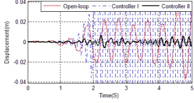
. Under the same earthquake excitation, the responses of the first storey displacements of open-loop and closed-loop systems which are composed with the controller I and II are compared in Figure 3. It can be seen from Figure 3 that the responses of the closed-loop system, which iscomposed with controller I, is becoming unstable. But on the contrary, controller II can still stabilizes the system without obvious degradation on performance.
Figure 3. Displacements of the first storey for the system with sensor faults.
Now, let us consider the uncertain case. We consider the uncertainties are applied to the stiffness and damping coefficients of the system, and assume the parameter uncertainties satisfying 0.4 , and 0.1i
t 1.3
i1, 2, 3, 4, 5, 6
. By solving the LMIs (12) and (19) , we obtain a robust sensor fault-tolerant state feedback controller which has the following gain matrix1971.1 1392.7 0.4189 143.41
1393.9 1971.1 1357.2 1.8704
1.7200 1455.9 1989.2 0.0212
1.8213 0.0129
143.41 0.1522 .
4.261 104.92
F
(25)
For description in brevity, we denote this designed controller as controller III thereafter.
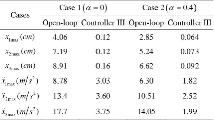
Under the earthquake excitation mentioned above, the responses of the first storey displacements of open-loop and closed-loop system which is composed with the controller III are shown in Figure 4. The displacements of the other two storeys and the accelerations of three storeys have a similar varying trend, which are omitted here. The maximum displacements and accelerations of two cases (case 1: 0; case 2: 0.4) are compared in Table 2. We can obtain from Figure 4 and Table 2 that no matter the parameter uncertainties exist or not, controller III is always effective to attenuate the responses of displacements and accelerations.
TABLE II.
THE MAXIMUM RESPONSES OF DISPLACEMENTS AND
ACCELERATIONS FOR THE SYSTEM WITH UNCERTAINTIES
Case 10 Case 20.4 Cases
Open-loop Controller III Open-loop Controller III 1max( )
x cm 4.06 0.12 2.85 0.064
2 max( )
x cm 7.19 0.12 5.24 0.073
3max( )
x cm 8.91 0.16 6.62 0.092
2 1max( )
x m s
8.78 3.03 6.30 1.82
2 2 max( )
x m s
13.4 3.60 10.51 2.52
2 3max( )
x m s
17.7 3.75 14.05 1.99
Ⅳ. CONCLUSION
The problem of sensor fault-tolerant vibration controller design for a class of buildings structural systems is considered in this paper. Based on Newton’s second law and matrix transformation, the structural system is described as a state-space model which contains sensor faults. Furthermore, based on Lyapunov stability theory, an LMIs-based condition for the system to be stabilizable is established. If the feasibility problem of the condition is solvable, the desired sensor fault-tolerant controller can be obtained for the closed-loop system to be stable with the performance
2
z t t
. The
condition is also extended to the uncertain case. Finally, simulation results show that the proposed controllers are effective for vibration attenuation of the structural systems with sensor faults.
ACKNOWLEDGMENT
The authors would like to thank the anonymous reviewers for their detailed review and constructive comments. This work was partially supported by National Natural Science Foundation (No. 51064008), Jiangxi Provincial Natural Science Foundation (No. 20132BAB 211032), and the Scientific Research Projects of Jiangxi University of Science and Technology (Nos. jxxj12037; jxxj12006) of China.
REFERENCES
[1] J. J. Zhang, L. L. He and E. C. Wang, “Active vibration control of piezoelectric intelligent structures,” Journal of computers, vol. 5(3), pp. 401-409, 2010.
[2] H. P. Du and N. Zhang, “Hcontrol for buildings with time delay in control via linear matrix inequalities and genetic algorithms,” Engineering Structures, vol. 30, pp. 81-92, 2008.
[3] X. Z. Xu, “Research of electrified railway harmonic suppression based on H-infinity control,” Journal of computers, vol. 7(12), pp. 3075-3081, 2012.
[4] Y. Chen, W. Zhang and H. J. Gao, “Finite frequency
H control for building under earthquake excitation,”
Mechatronics, vol. 20(1), pp. 128-142, 2010.
[5] L. Li, G. Song and J. Ou, “Nonlinear structural vibration suppression using dynamic neural network observer and adaptive fuzzy sliding mode control,” Journal of Vibration and Control, vol. 16(10), pp. 1503-1526, 2010.
[6] J. F. Hu, D. C. Zhu, “Vibration control of smart structure using sliding mode control with observer,” Journal of Computers, vol. 7(2), pp. 411-418, 2012.
[7] S. Sundaram, N. Sriram, N. Satish and S. Narasimhan, “Fault-tolerant adaptive control of nonlinear base-isolated buildings using EMRAN,” Engineering Structures, vol. 32(8), pp. 2477-2487, 2010.
[8] A. A. El-Badawy, A. H. Nayfeh and H. VanLandingham, “Neural network identification and control of a parametrically excited structural dynamic model of an F-15 tail section,” Shock and Vibration, vol. 7(6), pp. 355-361, 2000.
[9] W. Jiang, “The Application of the Fuzzy Theory in the Design of Intelligent Building Control of Water Tank,”
Journal of Software, vol. 6(6), pp. 1082-1088, 2011. [10]D. V. Balandin and M.M. Kogan, “LMI-based optimal
attenuation of multi-storey building oscillations under seismic excitations,” Structural Control and Health Monitoring, vol. 12(2), pp. 213-224, 2005.
[11]G. P. Cai, J. Z. Huang, F. Sun and C. Wang, “Modified sliding-mode bang-bang control for seismically excited linear structures,” Earthquake Engineering and Structural Dynamics, vol. 29, pp. 1647-1657, 2000.
[12]C. W. Lim, T. Y. Chung and S. J. Moon, “Adaptive bang-bang control for the vibration control of structures under earthquakes,” Earthquake Engineering and Structural Dynamics, vol. 32, pp. 1977-1994, 2003.
[13]C. Loh, P. Lin and N. Chung, “Experimental verification of building control using active bracing system,” Earthquake Engineering and Structural Dynamics, vol. 28(10), pp. 1099-1119, 1999.
[14]C. W. Lim, Y. J. Park and S. J. Moon, “Robust saturation controller for linear time-invariant system with structured real parameter uncertainties,” Journal of Sound and Vibration, vol. 294(1-2), pp. 1-14, 2006.
[15]C. W. Lim, “Active vibration control of the linear structure with an active mass damper applying robust saturation controller,” Mechatronics, vol. 18(8), pp. 391-399, 2008. [16]J. Wu, X. Li and K. He, “Rotor Crack Fault Diagnosis
based on Base and Multi-sensor Adaptive Weighted Information Fusion,” Journal of Software, vol. 7(7), pp. 1585-1592, 2012.
[17]Z. Li, G. Tan and Y. Li, “Fault Diagnosis Based on Improved Kernel Fisher Discriminant Analysis,” Journal of Software, vol. 7(12), pp. 2657-2662, 2012.
[18]M. Battaini and S. J. Dyke, “Fault tolerant structural control systems for civil engineering applications,” Journal of Structural Control, vol. 5(1), pp. 1-26, 1998.
[19]S. Suresh, S. Narasimhan, S. Nagarajaiah and N. Sundararajan, “Fault-tolerant adaptive control of nonlinear base-isolated buildings using EMRAN,” Engineering Structures, vol. 32, pp. 2477-2487, 2010.
[20]W. L. Zhang, Y. Chen and H. J. Gao, “Energy-to-peak control for seismic-excited buildings with actuator faults and parameter uncertainties,” Journal of Sound and Vibration, vol. 330, pp. 581-602, 2011.
[21]F. L. Weng, Y. C. Ding, G. Yang, L. Liang, and Z. Yu, “Less Conservative Stability Criteria for Discrete-Time Nonlinear Stochastic Singular Systems with Mixed Time-Delay,” Asian Journal of Control, doi: 10.1002/asjc.709, 2013.
electro-hydraulic actuated linear structural systems,” Earthquake Engineering and Engineering Vibration, vol. 11(1), pp. 73-82, 2012.
[23]Y. C. Ding, F. L. Weng and Z. A. Yu, “Actuator saturation and control design for buildings structural systems with improved uncertainty description,” Shock and Vibration, vol. 20(2), pp. 297-308, 2012.
Yuanchun Ding received his Master degree in Safety Science and Engineering from Jiangxi University of Science and Technology, China, in 2005. Now, he is a Ph.D. candidate at the State Key Laboratory of Fire Science, University of Science and Technology of China, China. His research interests include robust control, structural systems, time-delay systems and applications.
Falu Weng received his Master degree in Mechanical Engineering and Automation from Jiangxi University of Science and Technology, China, in 2005. Now, he is engineering Ph.D., graduated from Zhejiang University, China. His research interests include robust control, structural systems, time-delay systems and applications.