An Optimal methodology for efficient resource
distribution among contending Sims in a single RF
subsystem multi-sim UE
Ruchi Kansara
?1, Jitendra Otwani
†2, Niladri Shekhar Paria
‡3and Sajal Das
§4IntelTechnologies,Bangalore,560103,India
Abstract
With the evolution of wireless broadband technology and increasing demand of multi-sim User Equipment (UE), new challenges of resource sharing arise where conventional methods of creating small gaps in resource usage pattern of one SIM do not suffice. The advent of Voice over LTE (VoLTE) services accompanied by the immense mobile broadband demand of the users, require continuous resource availability on both the SIMs even in a single RF subsystem. Dual SIM Dual Active (DSDA) architecture that can meet the above requirements is not popular due to higher associated cost. In this paper, we consider the fundamental problem of resource sharing across SIMs in multi-sim architecture especially Single Receive Dual SIM Dual Standby (SR-DSDS) and Dual Receive Dual SIM Dual Standby (DR-DSDS). We formulate resource sharing as an optimization problem to maximize the ratio of resource allocation fairly for each contending SIM considering several important factors like current buffer occupancy, average time criticality of the buffer content and channel quality of respective SIM. We solve the formulated optimization problem using Karush Kuhn Tucker (KKT) conditions to derive the closed-form expressions for optimal resource allocation. We also compute the number of transitions possible with the derived optimal fair allocation in a practical multi-sim architecture. Additionally, we present the analytical results to depict the efficacy of the algorithm.
Received on 17 April 2019; accepted on 20 May 2019; published on 16 July 2019
Keywords: SR-DSDS, CQI, Buffer Occupancy, Time Criticality
Copyright © 2019 Ruchi Kansara etal., licensed to EAI. This is an open access article distributed under the terms of
the Creative Commons Attribution license (http://creativecommons.org/licenses/by/3.0/), which permits unlimited use,
distribution and reproduction in any medium so long as the original work is properly cited.
doi:10.4108/eai.16-7-2019.162212
1. Introduction
With the increased penetration of smartphone and wireless technology advancement, there is a tremen-dous increase in the demand of user data and voice traffic. Also, the improvement in capability of UE to house two subscriber identity modules (SIMs) give rise to a new challenge where modem designers have to design algorithms to allocate fair share of resources to both the contending SIMs in a multi-sim architecture. Impact of MSIM architecture on a radio access network is discussed in [1].
∗
R. Kansara is currently associated with Samsung Research India, Bangalore (Email:[email protected])
†
J. Otwani is currently associated with Intel Technologies, Bangalore (Email:[email protected])
‡
N. Paria is currently associated with NXP Semiconductors, Austria (Email:[email protected])
§
S. Das is currently associated with Intel Technologies, Bangalore (Email:[email protected])
Today there are various multi-sim architecture variants available in market. Among these, SR-DSDS is the most popular one as it has only 1 RF transceiver which makes it the most cost effective architecture. The conventional SR-DSDS architecture solves the challenge of RF sharing, when both the contending SIMs request for RF resource, by static priority based scheduling algorithms. This scheduling algorithm essentially creates a small gap in RF usage pattern for one SIM, when the other contending SIM resource request priority is higher. In [2], authors present a dynamic scheduling algorithm that weighs the procedures dynamically to resolve the resource conflicts.
Static and dynamic scheduling algorithms are effective only when one of the contending SIM is in idle discontinuous reception (DRX) mode i.e. need RF resource only for a short interval of time. Therefore, current DSDS equipment reduces the capability of UE by data preference on only one of the SIM and hence
the other SIM operates in idle mode. When the idle SIM receives a call, data traffic on the data preferred SIM observes large interruptions which diminishes the end user experience. This challenge was addressed partially in [3] by re-establishing the mobile data connection on the idle SIM when it receives a voice call on idle SIM.
With the advancement in technology, various new challenges are arising where both the contending SIMs need RF resource continuously. One such example is when a VoLTE call is established on one SIM and a video download is ongoing on the other SIM. An optimal solution for such a challenge is not addressed in literature yet. In this paper, we try to address this problem by developing a generic scheduling algorithm which provides optimal fair share among the contending SIMs instead of static or dynamic priority based scheduling which are sub-optimal in nature. The proposed algorithm takes various quality of service parameters as an input and generates the optimal allocation percentage for each contending SIM.
This paper is organized as follows. In section 2, system model is presented. In section3, we present the proposed unique RF resource sharing algorithm along with mathematical analysis for obtaining the closed form expression for optimal allocation. In section 4, the feasibility of the theoretical results are derived by introducing the time latency involved in each RF transition between the contending SIMs. Section 5, shows analytical results of proposed resource sharing algorithm and Section6contains concluding remarks.
2. System Model
In this paper we propose a unique resource sharing algorithm for DSDS UE, which effectively share the available RF resource that improves UE performance and end-user experience. The proposed algorithm shares either the single transmission path in DR-DSDS device or the RF resource in SR-DR-DSDS device considering several factors which affects the end user experience. These quality of service parameters serve as an input for the scheduling algorithm to generate the optimal fair share among contenders. Following quality of service parameters are considered,
(i) Data Buffer status of the corresponding SIM,
(ii) Delay or Latency requirements associated with procedure,
(iii) Link quality between UE and network
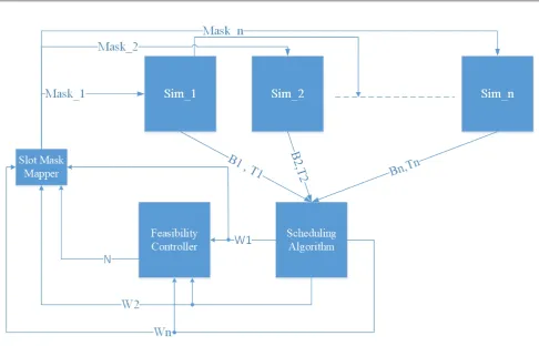
Fig 1 shows closed loop system of proposed MSIM architecture along with resource sharing algorithm. Based on above quality of service factors as an input, the scheduling algorithm computes optimal resource allocation which is further discussed in Section 3. The optimal resource allocation ratios are then fed to
feasibility controller that considers practical latency constraints required in RF switching to compute maximum supported number of transitions. Further details about the mathematical model used to compute the maximum possible transitions is explained in detail in Section 4. Then the results from scheduling algorithm and feasibility controller are fed to slot mask mapper which generates the bit mask that depicts the time allocation to utilize the common RF resource between the contending SIMs.
3. Scheduling Algorithm
Let us assume, n is the total number of SIMs supported by UE and the subscript i∈ {1,2, . . . , n}
represents ith SIM.B
i is the current buffer occupancy
corresponding to ith SIM and B
i ∈ {0,1, . . . , Bmax}. Ti
is the average time critical factor associated with the data present in buffer corresponding to ith SIM whereTi ∈ {1,2, . . . , Tmax}. CQIi is the channel quality
indicator corresponding to ith SIM such that CQIi ∈ {1,2, . . . , CQImax}. 0≤Wi ≤1 is the optimal percentage
of the frame allocation to ith SIM. Maski is the
optimal sub-frame mask generated based onWi andN,
whereN is maximum number of supported transitions computed by feasibility controller.
As the algorithm is executed at the UE,CQIis readily available and defines the link quality between UE and network.T represents the average latency requirements of the data traffic. This can be derived at UE based on the content generating application running at UE. It naturally motivates to allocate more resource to time critical applications as it leads to better end user experience.Bstands for the amount of buffer occupied
at the transmitter. In the downlink, buffer occupancy is linearly proportional to the amount of downlink shared channel (Physical Downlink Shared Channel, PDSCH) allocation by network for the UE. While in uplink direction, this is readily available at UE0s Medium Access Control (MAC) layer. Intuitively more data traffic should lead to more resource allocations and henceBis considered as one of the input parameter to the scheduling algorithm.
Scheduling algorithm aims to identify optimal Wi
that provides optimal fair share of the RF resource among contending SIMs. For the sake of simplicity, let us limit the mathematical model ton= 2 i.e. SR-DSDS assumption although the results obtained are equally applicable to any generic value ofn. Optimal allocation
Wi such thati∈[1,2] can be computed by solving the
below convex problem [4] if Bi ,0 ∀i (as contention
Figure 1. Proposed MSIM Architecture Model
maximize
W1, W2
W1+W2 (1a) subject to
(C1) : W1
CQI1B1T1
− W2
CQI2B2T2 = 0, (1b)
(C2) :W1+W2≤1, (1c)
(C3) :W1≥0, (1d)
(C4) :W2≥0., (1e)
(C5) :B1, B2,0. (1f)
The granularity over which this problem needs to be solved is the maximum of the Transmission Time Interval (TTI) of the associated procedure executed on the contending SIMs. To generalize, we consider this granularity to be of unit time. Objective function in (1) tries to maximize the sum resource allocation. As higher values of CQI, B and T indicate more occupied time critical buffer with good link, equation (1b) schedule larger proportion of frame Wi for the SIM with more
occupied time critical buffer. LargerCQIiBiTivalue will
lead to smaller hCQI1
iBiTi
i
which eventually results in higher Wi. Further, equation (1c) makes sure atmost
unit time is allocated collectively among the contending SIMs. Moreover, lower bound on the resource allocation for any contender can be 0 which is captured in
equations (1d) and (1e). Also, we should perform contention resolution only if both the contending SIMs have content in buffer which is incorporated in equation (1f). To solve the optimization problem, we use Karush Kuhn Tucker (KKT) conditions to compute optimal dynamic allocation ratio. Lagrangian for the optimization problem in (1) can be given as,
L(W1, W2;µ, λ) =W1+W2−λ(W1+W2−1)
−µ W1
CQI1B1T1
− W2
CQI2B2T2
!
. (2) For optimality we set ∇L(W1, W2;µ, λ) = 0. Hence,
optimality conditions can be further solved as in (3) and (4),
∂L(W1, W2;µ, λ)
∂W1
= 0
⇒1−λ− µ
CQI1B1T1
= 0. (3)
∂L(W1, W2;µ, λ)
∂W2
= 0.
⇒1−λ− µ
CQI2B2T2
= 0. (4)
Moreover, complementary slackness condition can be given as,
We obtain closed form expression of optimal resource allocationWi for all possible cases ofµandλ,
Case 1:µµµ= 0,λλλ= 0, Substituting this in equation (3)
and (4) yields impossible conditions and hence is an infeasible case.
Case 2:µµµ= 0,λλλ,0, Incorporating this in equation (3)
and (4) yieldsλ= 1. Using this result with equation (5) leads to following,
W1= 1−W2 (6) From (1b) and (6)
W1? = CQI1B1T1
CQI1B1T1+CQI2B2T2
(7)
W2? = CQI2B2T2
CQI1B1T1+CQI2B2T2
(8)
Case 3:µµµ,0,λλλ= 0, Substituting this in equation (3)
and (4) we get,
µ=CQI1B1T1=CQI2B2T2 (9) From (1b) and (9)
W1? =W2? (10)
Case 4:µµµ,0,λλλ,0, Incorporating this in equation (3)
we get,
λ= 1− µ
CQI1B1T1
(11)
Using (11) and (4) along withµ,0, we get,
CQI1B1T1=CQI2B2T2 (12) From (12) and (1b), it can be deduced that,
W1? =W2? (13) Additionally, using equations (13), (5) andλ,0 we get,
W1? =W2?= 0.5 (14) Case 1 results in invalid solution, Case 3 and 4 yields a deterministic fair allocation among SIMs that is independent of CQI, Buffer Occupancy and Time criticality parameters. Only Case 2 yields an optimal dynamic allocation that takes into account various important quality parameters like CQI, Buffer occupancy and Time criticality of the buffer content. Eventually all three cases yields the maximization of objective function but there is only one result which is dynamically choosing allocation based on various factors of interest. Hence, we consider case 2 results as the closed form optimal allocation expression for
W1? andW2?. The closed form expression dynamically
generates larger allocation to the more occupied time critical buffer with better link quality SIM contending for the resource.
Now, we need to figure out whether contiguous sub-frames allocation will be optimal or a certain pattern will generate optimal outcome. Wi? does not consider the practical RF outage latencies involved in switching between the contending SIMs. Hence, in the subsequent section we try to address this and compute the maximum transitions possible considering RF switch time latencies.
4. Feasibility Controller
For each transition of operation between contending SIMs, RF needs to re-tune which results into Tx/Rx blanking period. During this period, I/Q samples become invalid resulting in only fraction of total time utilized for actual transmission and reception. As the number of transitions increase, UE resource utilization decreases, thus it should be considered as a factor for generating optimal mapping patternMaski by slot
mask mapper. In this section, we try to compute the maximum possible transitionsN givenWi?is known.
Let us assume,
(i) τ is the transition delay while switching between the contending SIMs, it is system specific and is fixed based on the UE design.
(ii) F is the total time duration over which resource allocationWi is computed (in section3unit time
is considered for the sake of simplicity). In other words, F is a number multiple of the longest of TTI associated with contending SIMs.
(iii) Fi is the time allocation corresponding to Wi
associated with SIMisuch thati∈ {1,2, . . . , n}and
Fi = [1,F).
(iv) θis the threshold indicating minimum fraction of timeF which makes resource allocation feasible for a practical system.θis also a system specific fixed parameter depending on usecase, e.g.Fis set such thatF×θis multiples of TTI.
(v) N is maximum possible number of transitions. (vi) Ni is the number of transitions corresponding to
SIMisuch thati∈ {1,2, . . . , n}and for a practical
systemNi ≥1.
In this section we identify maximum possible transi-tionsNand provide to the slot mask mapper along with frame allocationWi, as depicted in Fig.1.Fifor a system
can be given by,
For a practical systemFi is bounded as,
Fi > θF (16)
SubstitutingFifrom (15) into (16) gives an upper bound
onNi as follows,
Ni < FWi −θF
τ (17)
Equation (15) depictsFifor SIMireduces fromFWidue
to transition delayτ for each transitions. To determine feasibility of the systemFi must be greater than certain
thresholdθof total timeFas given in (16).
Maximum possible number of transitions N is limited by the minimum ofNi as ith SIM could only support
atmostNi transitions, given in (18).
N =min(N1, N2, . . . , Nn) (18)
From (17), it can be deduced thatNi∝Wi, hence
N ∝min(W1, W2, . . . , Wn) (19)
Finally, the computed N is informed to the slot mask mapper along with Wi to generate the optimal
feasible allocation pattern for the contending SIMs. As we are already aware that the Uplink HARQ messages receive its acknowledgment with a pre-defined delay. Hence, the mapper block will take the optimalWi and
N as an input and generate the optimal pattern of resource allocation for SIMi catering the transmission to acknowledgment delay. Fig. 1 depicts the block diagram of the proposed MSIM scheduling architecture along with slot mask mapper that maps Wi and N to
Maski. Hence, with the proposed architecture, we are
able to distribute optimally the RF resource between the contending SIMs for a practical system.
5. Analytical Results
We considered the SR-DSDS i.e.n= 2 case for obtaining the optimal frame allocation ratio (W) and maximum possible transition count (N) computed in section3and 4 respectively. This section studies and demonstrates the impact of varying the quality of service parameters
CQI,B andT on the optimal frame allocation W and maximum possible transition countN. As various 3GPP standards specify, CQI in the range of [1,30], we set
CQImax= 30. Generally, a finite buffer length will be
available at the transmitter, hence we set Bmax= 10.
Average time criticality can be quantified in the range of [0,1], but for ease of numerical computation we scale
Tmax to 10. The associated quality parameters used for
obtaining the analytical results of the mathematical modeling are provided in figure0s caption.
As conventional scheduling algorithms can only generate binary decision about resource usage based on static or dynamic priority, the proposed architecture
0 5 10 15 20 25 30
Sim
1 Channel Quality Indicator (CQI1)
0 0.5 1
Frame Allocation(%)
(a)
W1 W2
0 10 20 30
CQI
1
0 50 100 150
min(N
1
,N
2
)
(b)
0 10 20 30
CQI
1
0.6 0.7 0.8 0.9 1
Frame Utilization(%)
(c)
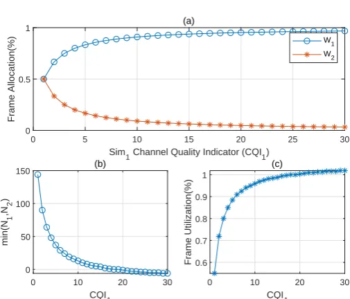
Figure 2. Frame Allocation and max transitions vs CQI1 for (CQI2, B1, B2, T1, T2) = (1,1,1,1,1) respectively
cannot be directly compared for efficacy measurements. Hence, we simulate the proposed mathematical model and discuss inferences drawn from the analytical results. Each analytical result plot is further sub-divided into three subplots that depicts,
(i) The impact of variation ofCQIorBorT on frame allocationW1andW2,
(ii) The maximum possible transition count N for optimal allocationWi and fixedF= 640 ms,τ = 2
ms andθ= 5%,
(iii) The lower bound on frame utilization period for Rx/Tx considering same fixed parameter setting as in (b).
5.1. Impact of CQI variation on Scheduling Algorithm
Here we study the variation ofCQIassociated with SIM 1 from 1 to 30 while all other input parameters are kept fixed. In Fig.2(a), buffer occupied and time criticality of both the SIMs is equal.CQIobserved by SIM 2 is fixed at 1. The algorithm initially allocates equal resource to both SIMs atCQI1= 1 and then dynamically allocates more resources to SIM 1 asCQI1increases. In Fig.2(b), peak of max possible transitions N is observed whenCQI1= 1, i.e., when equal resources are allocated to both SIMs. Later as CQI1 increases W2 reduces and hence the curve ofN followsW2. This inference follows from (19). It can be observed in Fig. 2(c) that as N
decreases, actual frame utilized for Rx/Tx increases. It follows naturally as total transition delay will beN ×τ
where τ is fixed system driven parameter. This is the simplest permutation case to depict effect of varying
0 5 10 15 20 25 30
Sim
1 Channel Quality Indicator (CQI1)
0 0.5 1
Frame Allocation(%)
(a)
W1 W2
0 10 20 30
CQI
1
0 50 100 150
min(N
1
,N
2
)
(b)
0 10 20 30
CQI
1
0.6 0.7 0.8 0.9 1
Frame Utilization(%)
(c)
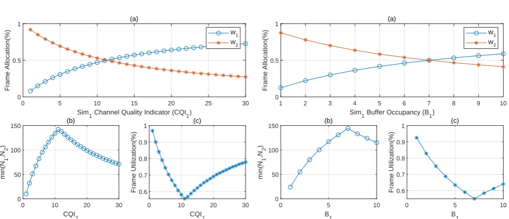
Figure 3. Frame Allocation and max transitions vs CQI1 for (CQI2, B1, B2, T1, T2) = (15,7,3,4,7) respectively
In Fig.3(a), SIM 1 buffer is occupied more as compared to that of SIM 2 whereas the buffered content is more time critical in SIM 2. CQI observed by SIM 2 is set to 15. The scheduling algorithm dynamically chose to allocate more allocation to time critical buffer tillCQIquality of SIM 1 is inferior. AtCQI1= 11 even though the CQI1 is inferior to CQI2, the algorithm dynamically allocates more resources to SIM 1 as buffered content quantity in SIM 1 is more compared to that of SIM 2. Therefore, this plot depicts the efficacy of the mathematical model presented in section3. Fig. 3(b) curve follows min(W1, W2) similar to the inference made while discussing Fig. 2(b). The peak for max possible transition countN appears atCQI1 = 11 when
W1 and W2 are equal. Fig. 3(c) is inferred to be a complement of Fig.3(b). Similar inference can be made in all the subsequent analytical results and hence this redundant description of sub-plots (b) and (c) is further omitted for the sake of reader0s interest.
5.2. Impact of variation of Buffer occupancy (B)
In Fig.4(a) the impact of varying SIM 1 buffer occupancy (B1) on resource allocationW1andW2is depicted.CQI andT are kept fixed and same for both the SIMs. SIM 2 Buffer occupancyB2is set to 7 andB1is varied from 1 to
Bmax. It can be observed that the algorithm dynamically
chose to allocate more resource to more buffered SIM i.e. SIM 2 until B1=B2= 7. Beyond this inflection point, resource allocation crossover is observed where algorithm chose to assign more resources to more buffered SIM 1 as compared to that of SIM 2.
1 2 3 4 5 6 7 8 9 10
Sim
1 Buffer Occupancy (B1)
0 0.5 1
Frame Allocation(%)
(a)
W1 W2
0 5 10
B
1
0 50 100 150
min(N
1
,N
2
)
(b)
0 5 10
B
1
0.6 0.7 0.8 0.9 1
Frame Utilization(%)
(c)
Figure 4. Frame Allocation and max transitions vs Buffer Occupancy B1 for (CQI1, CQI2, B2, T1, T2) = (30,30,7,1,1) respectively
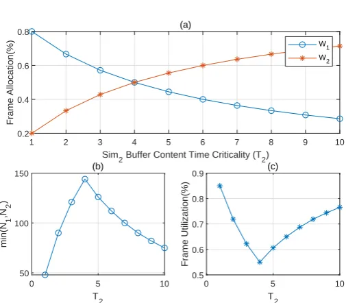
5.3. Impact of variation of Time criticality (T)
In Fig.5(a), the impact of varying the average time criticality parameter (T) on resource allocation W1 and W2 is demonstrated. CQI and buffer occupancy
B are kept as similar constants for both the SIMs. Average time criticality, T1 of SIM 1 buffered content is fixed at 4 whereasT2 associated with SIM 2 is varied from 1 to Tmax. Similar inferences can be made about
inflection point and resource allocation crossover as that of Section 5.2. T1=T2= 4 is the inflection point where resource allocation crossover is observed.
5.4. Impact of utilization threshold (
θ
) and transition
delay (
τ
) on Feasibility Controller
Table 1. Impact of variation of θ on N with (F,τ) = (640ms,2ms) and (CQI2, B1, B2, T1, T2) = (15,7,3,4,7)
NNN(((CQICQICQI111))) θθθ=5% θθθ=10% θθθ=20%
N
NN(1) 51 -6(Not -38(Not
realizable) realizable)
N
NN(3) 51 35 3
N N
N(11) 142 126 94
N N
N(30) 71 55 23
Table1, shows impact of frame utilization threshold
1 2 3 4 5 6 7 8 9 10
Sim
2 Buffer Content Time Criticality (T2)
0.2 0.4 0.6 0.8
Frame Allocation(%)
(a)
W1 W2
0 5 10
T
2
50 100 150
min(N
1
,N
2
)
(b)
0 5 10
T
2
0.5 0.6 0.7 0.8 0.9
Frame Utilization(%)
(c)
Figure 5. Frame Allocation and max transitions vs Buffer Content Time Criticality T2 for (CQI1, CQI2, B1, B2, T1) = (30,30,10,10,4) respectively
Table 2. Impact of variation of τ on N with (F,θ) = (640ms,5%) and (CQI2, B1, B2, T1, T2) = (15,7,3,4,7)
NNN(((CQICQICQI111))) τττ=2ms τττ=10ms τττ=20ms
N N
N(1) 51 2 1
N N
N(3) 51 10 5
N N
N(11) 142 28 14
N N
N(30) 71 14 7
such cases, feasibility controller will decide not to apply dynamic resource sharing.
Table 2, shows impact of transition delay τ on maximum possible transition countN. Asτ increases, total duration over which resources could be utilized reduces and thus N decreases. For instance, when
CQI1=1 varyingτfrom 2 ms to 20 ms,N reduces from 51 to 1.
For the sake of completeness, let us also compute the lower bound of threshold θ for which the feasibility condition satisfies. Considering fixed system parameters as (F, τ) = (640ms,2ms) and (CQI1, CQI2, B1, B2, T1, T2) = (1,15,7,3,4,7), W1 and
W2 from equations (7) and (8), givesW1= 0.0816 and
W2= 0.9184 and to satisfy feasibility constraint, N must be at least set to 1. Substituting W1, W2 and N in (17), givesθ= 7.8% as the upper bound. A similar computation can be done for each case, which however is omitted to maintain the readability of the paper.
6.
Conclusion
In thiswork,weconsideredthefundamentalproblem of resource sharing, inherently associated with multi-sim single RF subsystem UE. We proposed a multi-sim architecture with a scheduling algorithm and a feasibility controller that optimizes the shared resource across the contending SIMs. We formulated an optimization problem that optimally allocates the shared resource while dynamically choosing the allocation based on various important quality of service parameters like CQI, buffer occupancy and time criticalityof buffered content.Further, extensive mathematicalanalysisisdoneusingKKTconditionsto computetheclosedformoptimalframeallocationratio. Subsequently,weincorporatedtheRFblackoutperiods involvedinswitchingbetweentheSIMsforapractical multi-sim architecture, to compute the maximum numberoftransitionspossible.Subsequently,analytical results presented, emphasize the effectiveness of proposedarchitecture.Wealsotabulatethecaseswhere feasibility conditions fail, hence render scheduling algorithm ineffective. Therefore,theproposed scheme brings significanta dvantageo vert hec onventionalRF resource sharing method especially in SR-DSDS and DR-DSDSarchitectureandhencehelpstodesignbetter multi-simcapablemodem.
7.
Copyright
statement
Presented at WinTechCon-2019, organized by IEEE CAS Bangalore Chapter, IEEE Bangalore Section, and IEEEWiECouncilBangalore.
7.1.
Copyright
TheCopyrightlicensedto
EAI
.Acknowledgement. Authors would like to thank Ashwini Bharade ([email protected]) for her contribu-tions tothiswork.SheisassociatedwithIntelTechnologies BangaloreasaModemSoftwareDevelopmentEngineer.
References
[1] Ericsson, “Dual-sim dual-standby ues and their impact on the ran.” 3GPP Technical Report RP-111637, 2011. [2] J. L. Buthler and T. Sorensen, “Dynamic multi-sim
gap creating procedure,” in 2016 IEEE 84th Vehicular Technology Conference (VTC-Fall). IEEE, 2016, pp. 1–5. [3] L. Hang and C.-P. Hsu, “Simultaneous voice and data
for dual-sim-dual-standby (dsds) wireless device,” Jun. 23 2015, uS Patent 9,066,330.