Image Transmission in MIMO-UWB Systems Using
Multiple Description Coding (MDC) Over AWGN and
Fading Channels with DS-PAM Modulation
Ali Arshaghi
1,Mehdi Nooshyar
2, Mohsen Ashourian
31. Department of Electrical Engineering, Central Tehran Branch, Islamic Azad University, Tehran, Iran 2. Electrical Engineering Department, Faculty of Engineering, University of Mohaghegh Ardebili, Ardabil, Iran
3. Computer Engineering Department, Faculty of Engineering, University of Majlesi Branch, Islamic Azad University, Isfahan, Iran
*Corresponding Author email: [email protected]
ABSTRACT: UWB communication system is a new technique with high performance that has low power consumption and used in wireless communications for ultra-data rates. In this paper, the image transfer techniques using MIMO-UWB system with multiple description coding (MDC) format over AWGN and fading channels are proposed. The proposed methods ensure that in the packet loss scenario due to channel errors, images with acceptable quality without need of retransition can be reconstructed. Also, the performance of the single description coding and MDC method are studied. The simulation results show that the performance of the proposed method is promising.
Keywords: Direct Sequence, UWB, AWGN, MDC.
INTRODUCTION
Wireless multimedia communication has played an important role in the transmission of images in recent years. Many technologies have been proposed for improving the performance of the transmission and achieving the best quality (Emami,s.,2013). Since image transmission includes non-uniform value of data bits, it has more challenges than data transmission. In wireless environments, the challenges of image transmission are increased. In the various networks such as mobile, satellite, wireless sensor networks, ad hoc networks, the images (and videos) transmit over a wireless channel.
13 CDF, the performance of the image transmission is studied. In (Bai,Z, 2005) wireless image transmission using Turbo and Reed-Solomon codes for measurement continuous errors have been discussed. In (Thomos,N et al, 2005) a method is proposed showing the modernization of missing blocks in Wavelet-Domain is very effective. Many researches have been done on image coding and improving error rate.
Input Multiple Output (MIMO) systems have more bandwidth and are suitable for broadband applications. The combination of UWB and MIMO technology is a good way to get more data rates of 1 Gb/s in wireless communications (Shantanu D.R et al, 2002).
The multiple description coding (MDC) technique is used to protect the image transmission over wireless channels (Kaiser.T et al, 2009). In (Wang, Y et al, 2005), the others methods such as, multi-layer coding (MLC) and joint source-channel coding (JSCC) are presented.
In this paper, we investigate the transmission of multiple description images with antipodal modulation over DS-UWB channels in MIMO system. Also, we will consider the system over AWGN and Fading channels. By changing in all blocks and the effective parameters in the system, influence of each block is studied. Then, the simulation results are compared together with the method of MDC and single description coding SDC.
The paper has been organized in the following way. Section 2 describes the DS-UWB system model with PSK modulation. In section 3 the image MDC and its implementation are given. The model of MIMO system is described in Section 4. The simulations results over AWGN and fading channels are presented in Section 5 and 6, respectively. Finally, the conclusions and important issues for future research are presented.
DS-UWB System Model
Consider a UWB system with N u active users. The block diagram of DS-PAM UWB system for a user is shown in Fig.1.
Figure1. Transmission diagram of the DS-PAM-UWB System
Each user is assigned a pseudo random code
wtr
of duration Tf= NcTc, where Nc and Tc are the processing chip gain and chip time, respectively. The kth user's transmitted signal can be expressed as follows (Ghavami,M et al, 2004).str
(k)(t) = ∑ ∑ dj
(k) Nc−1
n=0 cn
(k)
wtr(t − jTf− nTc) +∞
j=−∞ (1)
C kn wtr
t jT f nT c
j
N c
n d kj t
s ktr
1 0 Where
D kj ,
d kj, N s, C k
n and wtr
t denote the data vector, the kth user's modulated data symbols in the jth frame such that
D k N s j d kj 2, the pulse repetition time, is the spreading chip whose duration T c and is the transmitted monocycle waveform, respectively (Bai,Z & Kwak.K, 2005).
The received signal by Kth user at the receiver can be written as (Bai,Z & Kwak.K, 2005): r(t) = ∑ Akstr
(k) (t − τk) Nu
k=1 + n(t) (2)
N u s krec
t k
n
tk Ak
t
r
1
where Ak denotes received amplitude of the kth user’s signal and τk is the propagation delay of the kth user and n(t) is white Gaussian noise with power spectral density σn2 .
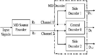
14 An ideal multiple description system is consist of two channels. The ith channel may be failed (disconnected) by probability pi, i {1,2}.In this case, decoder be notified, but encoder is not. Also, the basic assumption is that the both channels don't interrupted (failed) simultaneously. Fig. 2 shows that the block diagram of MD source coding using an ideal MD network. Decoder copies the original signal and sends them through two separate channels (Kamnoonwatana, N, et al, 2012)
Figure 2. Multiple description ideal system with 2 channels.
The central decoder receives both descriptions (versions) and reconstructions the signals with high-quality. The performance of the central decoder is better than two side decoders. Each of the side decoders receives one of the two descriptions (versions) and with reconstructions the signal with low quality but acceptable (Vaishampayan, V, 1993) .
In (Franchi, N et al, 2005), the multiple description scalar quantization (MDSQ) for the MD coding has been proposed. In this method, several quantization levels are used so that the levels have overlap with each other. This overlap causes correlation between descriptions.
The multiple description coding is one of the source coding techniques that protects the quality of image against the errors of the channel. From original image, 4 sub-images using MDC with Subsampling method are provided. As shown in Fig. 3, pixels corresponding with circle, square, rhombus-shaped and stars are separated from the original image in versions 1, 2, 3 and 4, respectively.
Figure 3. Polyphase Subsampling in place domain (Image)
Figure 4 shows how versions of the original image are created for a simple example (Kamnoonwatana, N et al.,2012).
15 As another example, sub-images of 256×256 Cameraman image with MDC subsampling method are shown in Figure 5, in which dimension of each sub-image is 128 × 128.
b a
d c
Figure 5. Sub images of Cameraman image
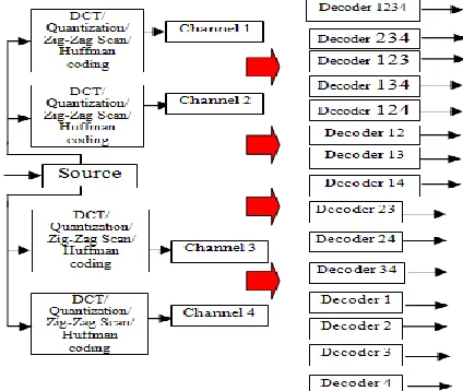
Each version is divided to the 4 × 4 block. The DCT transform of each block is calculated and the DCT coefficients are mapped to a vector and done procedures the quantizing, source and channel coding and Spreading and modulate and we'll send signals to the channel, and in the receiver will do the reverse this steps. In Figure 6 a block diagram of the overall four description coding drawn. According to Figure 4 original input image to two or more versions data that of the so-called version (sub image) will be divided.
Each of versions separate have satisfactory quality of the original image to their. If all copies must be received at the receiver, then the decoder with quality very good reconstructed image data. But if the number of copies that are lost when crossing the channel decoder with the quality relatively low reconstructed data (Brown, T et al., 2012).
Figure 6. The structure of four versions coding system based DCT
In this system total 15 different scenarios for the reconstructed versions and image in receiver may happen. For example, Decoder 1234 indicates that all four versions have been received and Decoder 124 indicates that the three versions 1, 2 and 4 have been received and Decoder 34 indicates that both versions 3 and 4 received and Decoder 1 indicates that only one copy is received.
Mimo
16
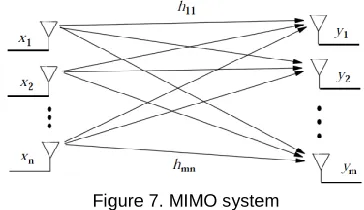
Figure 7. MIMO system
This system can be expressed as the following equations and discrete-time model:
• • • • • • • • • • • • • • • • • • • • • • • • N m N xn x hmn hm h n h y m
y 1 1
1 1 11 1 (3) N x H
y
(4)
where xis the n-dimensional transmitted symbols, N is assumed to be the m-dimensional AWGN noise vector, H contains zero mean complex circular Gaussian random variables
hij
that represent the (gain) channel from transmit antennaj
to receive antennai
(Cassioli, D et al., 2002).In wireless communication networks, the performance is improved by using spatial diversity. In a wireless communication system, because of Fading, coefficient error in the mean value of the signal to noise ratio, has increased a lot, in comparison with AWGN channels. The use of spatial diversity (multiple antennas at the transmitter or receiver use), is one of effective methods to deal with the destructive effects of these channels. Composition of the spatial diversity with other types of diversity, such as time or frequency, can dramatically improve the system performance. Space- time codes can make some degree of diversity in both time and space, simultaneously.
In this study, a MIMO system with the orthogonal space-time block code (OSTBC) encoder for encoding an input symbol sequence, is used for diversity. The block maps the input symbols block-wise and concatenates the output codeword matrices in the time domain. Also, we use an OSTBC combiner which combines the input signals (from all of the receive antennas) and the channel estimate signal to extract the soft information of the symbols encoded by an OSTBC. A symbol demodulator or decoder would follow the Combiner object in a MIMO communications system.
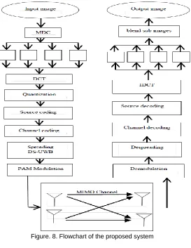
Algorithms for image transmission in transmitter
1. Image reading
2. DCT transformation of the image 3. quantization of DCT coefficients 4. Using source coding (arithmetic) 5. Channel coding (convolutional)
6. Spreading signal in Method of DS-UWB 7. PAM modulation method.
8. Passing signals over Fading Channels
algorithm of Get the picture in the receiver side is just reverse above algorithm, And the received signals by the antennas receiver , and perform the inverse process of this algorithm will reach to image reconstruction.
17
Figure. 8. Flowchart of the proposed system
SIMULATIONS RESULTS
First, 256 × 256 Cameraman image is read. in next block method versioning MDC (Subsampling) will do the dimensions of versions are 128 × 128.Then in this copies get DCT transform and then quantized to the next block use an arithmetic code that is a source coding and at the next block use convolutional code for channel coding and next with techniques direct sequence (DS), do Spreading of signals and use of PAM modulation. Channel is assumed to be AWGN MIMO and get the number of antennas once 2 × 2 and once 2 × 1 and we get Signal-to noise ratio to 15, SNR = 15dB. the next blocks reverse works done in the transmitter. Do Demodulation and next Despreading and channel decoding and source decoding and apply IDCT to the Signals and after combining received sub images with dimensions 128 × 128 restored image with dimensions 256 × 256 is obtained. received Versions in the receiver is shown in Figure 9.
a b
c d
18 Reconstructed images of the 4 versions of 128 × 128 are shown in Figure 10 to dimension 256 × 256. This version received simulated for different SNR, and the SNR = 15dB showed in here.
Figure 10. Image after composition of the sub image DS-PSK
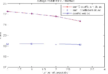
Average PSNR values for different versions of the lost using multiple description coding with DCT transform are shown in Table 1. In cases where a prescription is lost, with versions obtained by averaging the match pixels, are obtained approximations copies of the lost.
Table 1. PSNR to the state of lost prescriptions PSNR
SNR=15dB Number of copies
lost
22.2667 0
22.0501 1
21.7961 2
21.3668 3
In Table 2 PSNR Image received for state that only dc coefficient original version have been received, it shows. PSNR image reconstructed in this case based on the number of copies is lost investigate.
Table 2. PSNR DC coefficient images PSNR
SNR=15dB Number of copies
lost
19.1936 0
19.2127 1
19.1929 2
19.1416 3
Figure 11 shows PSNR values for the number of copies that have been lost.
Figure 11. Mean values of PSNR (dB) for different versions of the lost
19
Figure 12. Image obtained without MDC
Table 3. PSNR image without MDC PSNR image
25.4000 image cameraman
without MDC
In other trial we alter number antenna .Table 4 presents the PSNR in the received image DS-PSK UWB system with SNR = 5,10,15 dB and MIMO 2 × 1.In this case, main coefficient DCT have been received.
Table 4. PSNR image MIMO 2*1 PSNR image
22.2586 image cameraman
In Figure 13 PSNR than SNR with MDC method for restoration image with dimensions 256 × 256 is shown. MIMO system once 2 × 2 and once 2 × 1 Assume and we show the results.
Figure 13. PSNR than SNR of MDC method with DCT
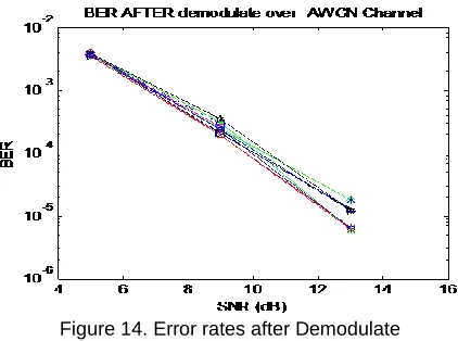
Fig. 14 the SNR Fading channel than BER (error rate) of 12 signals (3 coefficients of four copies that are 12) obtained before modulate and after Demodulate is draw
.
Figure 14. Error rates after Demodulate
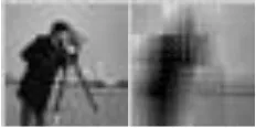
20 For another state received image DS-PSK UWB system using the MDC to dimensions 32 × 32 in fading channel, Fading channel, SNR = 15dB, MIMO 2 × 2 and raised Spread factor signals. The results can be seen in Figure 15 and 18. In this state too dc coefficient and ac two side coefficient original copies given and the fusion them image is obtained. Due to the large is image size, image size 32 × 32 we got. In this case, the PSNR is 19.5713.
Figure 15. Origonal image 32 × 32 Fig. 16. Image obtained 32 × 32
Performance DS-UWB system in fading channels )The received signal in fading environment (
If L is multi-streaming component in the channel. the received signal of desired user is equal to: r(t) = ∑ Ak∑ ∑ djpn
Nc−1 n=0 +∞ j=−∞ L
k=1
wrec(t − jTf− nTc− τk) + n(t) (5)
t jT f nT c k
n
twrec
pn L
k j
N c
n d j
Ak t
r
1
1 0
(5)
whereAk amplitude of kth multi-streaming component,wrec
t is the received pulse shape. d jreceived data Symbols in the frame j, j the number of pulses sent, T f length a frame, and kis the relative delay kth component and is equal k 1
k1
T c, pna pseudo-noise sequence and n
t is the total noise and interference received, including thermal noise, interference of other UWB transmitters and interferences of narrowband.In UWB communication systems can be used RAKE receiver. in (Cassioli,D, Win et al, 2002, YANG, LI et al, 2011) Examples of RAKE receiver has been proposed for use in UWB systems. Figure 17 show below is an example block diagram of the RAKE receiver that in it instead branches of RAKE receiver put on the most powerful components, put it on the component with lower deferment.
Figure 17. Block diagram of the PRAKE receiver
Simulation DS-UWB system in the Fading Channel
21 DCT, quantization, source coding, channel coding ane next to the Direct Sequence (DS) technique, Spreading the signals, and using the PAM modulation. channel is MIMO and Fading that we get number of the antennas once 2 × 2 and once 2 × 1 and we get the signal-to noise ratio 15 (SNR = 15dB). next blocks are reverse operations done in the transmitter.
Versions of the images of get descriptions in the receiver in Fading channel similar Figure 7 and renovation image of this received descriptions is the same Figure 8.
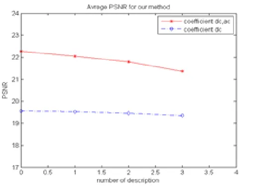
Average PSNR values for different number of copies of the lost coded using four versions are shown in Table 5.
Table 5. PSNR to the state of lost prescriptions PSNR
SNR=15dB Number of copies
lost
22.2642 0
22.0482 1
21.7946 2
21.3649 3
In Table 6 PSNR Received Image DS-PAM UWB systems and SNR = 15dB, and 2 × 2 MIMO is shown. In this method, only the DC coefficients original versions sent, have been received. PSNR image reconstructed in this case investigate based on the number of copies is lost.
Table 6. PSNR DC coefficient images PSNR
SNR=15dB Number of copies
lost
19.5686 0
19.5240 1
19.4671 2
19.3604 3
Figure 18 shows PSNR values for the number of copies that have been lost.
Figure 18. Mean values of PSNR (dB) for different versions of the lost
Output image without using MDC (SDC) to obtain,in this method of loss image is likely. DS-PAM modulation and dimensions copies 128 × 128, Channel Fading, SNR = 15dB, 2 × 2 MIMO, and signals are Spread. Important coefficients DCT have sent, in Table 7 PSNR image without the MDC is shown.
Table 7. PSNR image without MDC PSNR image
25.4000 image cameraman
22 In another experiment, we change the number of antennas. Table 8 PSNR Image DS-PAM UWB Systems with Channel Fading, SNR = 5,10,15 dB and 1 × 2 MIMO is shown. In this case, important coefficients DCT have been received, too.
Table 8. PSNR image MIMO 2*1 PSNR image
22. 2642 image cameraman
In Figure 19 PSNR than SNR with MDC for restored image with dimensions 256 × 256 is shown. MIMO system once 2 × 2 and once 2 × 1 Assume and we show the results.
Figure 19. PSNR than SNR of MDC method with DCT in Fading Channels
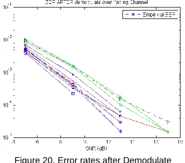
Figure 20 the SNR Fading channel than to BER (error rate) of 12 signals (3 coefficients of four copies that are 12) obtained before modulate and after Demodulate is draw.
Figure 20. Error rates after Demodulate
Error rate before of the channel coding and after the channel decoded shown for 12 signal that all set to zero. Therefore, the channel code is used to correct all errors.
23
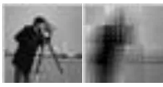
Figure 21. (a) Origonal image 32 × 32 and (b) Image obtained 32 × 32
CONCLUSION
In this paper, following the introduction of ultra-broadband systems, the performance of DS-UWB systems with antipodal PAM modulation in AWGN and Fading channels analysis. Multiple description coding of the image, DCT block of the original image, and how to get the pictures were told. MIMO system in the two state 2 × 2 and 2 × 1 was studied and the results were compared. Image transmission by states Spreading, Snr different, modes MDC, SDC, number selected coefficients of prescriptions survey. It was observed that at low SNR, PSNR not changed. several scenarios MDC Decoding were examined and it was shown that the proposed system for image transmission have Robustness against missing versions
REFERENCES
Bai,Z,Kwak.K, (2005)” Performance Analysis of Multiuser DS-PAM and TH-PPM UWB Systems in Data and Image Transmission,” IEEE Conf.
Bai,Z,W.Zhang,W, Xu,S, Liu,W, Kwak,K, (2005) ” On the Performance of Multiple Access DS-BPAM UWB Systems in Data and Image Transmission,” IEEE Conf
Bilal,M, Saleem,R, Abbasi,H.H, (2017) “An FSS-Based Nonplanar Quad-Element UWB-MIMO Antenna System ”, IEEE Antennas and Wireless Propagation Letters , vol.16, pp. 987 - 990
Brown, T, Kyritsi, P, Carvalho, E. D, (2012) " Practical Guide to MIMO Radio Channel", John Wiley & Sons
Cassioli, D, Win, M. Z, Vatalaro, F, Molisch, A. F, (2002) "Performance of low-complexity rake reception in a realistic UWB channel," in Proc. IEEE Intl. Conf. on Communications, ICC’2002, vol. 2, pp. 763-767
Cassioli,D, Win, M. Z. ,Vatalaro,F, Molisch, A. F, (2002) "Performance of low-complexity rake reception in a realistic UWB channel," in Proc. IEEE Intl. Conf. on Communications, ICC’2002, vol. 2, pp. 763-767
DiBenedetto,M.G, Kaiser,T,(2006)” UWB Communications Systems: A Comprehensive Overview”. Cairo, Egypt: Hindawi
Emami,s.(2013) ”UWB Communication Systems: Conventional and 60 GHz”, Springer New York,
Franchi, N., Fumagalli, M, Lancini, R.Tubaro, S,(2005) "Multiple Description Video coding for scable and robust transmission over IP," IEEE Trans. Circuits and Syst. Video Technol. Vol.15, no. 3, pp.321-334
Ge,L,Zhang,H, Guo,H,Wu,H, (2017) “High performance compressed sampling for OFDM-UWB systems”, IEEE Journals & Magazines China Communications, vol.14. no.3, pp. 75 - 86
Ghavami,M, Michael,L.B,(2004) “Ultra Wideband Signals and Systems in Communication Engineering”. New York: Wiley
Kaiser.T,Zheng,F,Dimitrov.E, (2009) "An Overview of Ultra-Wide-Band Systems With MIMO," in proc. Of IEEE,vol.97.no.2,pp.285 – 312
Kamnoonwatana, N, Agrafiotis, D, Canagarajah, C.N, (2012) " Flexible Adaptive Multiple Description Coding for Video Transmission ", IEEE Trans. Circuits, Syst., Video Technol, vol. 22, no 1, pp. 1-11
Kamnoonwatana, N, Agrafiotis,D. Canagarajah, C.N,(2012) " Flexible Adaptive Multiple Description Coding for Video Transmission ", IEEE Trans. Circuits, Syst., Video Technol, vol. 22, no 1, pp. 1-11
Kshetrimayum, R.S, Guwahati, G. IIT,(2009) " An introduction to UWB communication systems" Potentials, IEEE, vol. 28, no. 2, pp. 13
L. Yang,L. and. Giannakis, G. B,(2004) "Ultra-wideband communications An idea whose time has come," IEEE Signal Process. Mag., vol. 21, pp. 26–54
Lv,T,Zhang.H,(2010) ” A Selective Approach to Improve the Performance of UWB Image Transmission System over Indoor Fading Channels,” IEEE Conf.
24 Okiljevic, P, Pokrajac, I.P, Vucic, D.(2011) " Cyclic spectral analisys of UWB impulse radio signals with DS-PAM",
IEEE Conf. Telecommunications Forum (TELFOR), 19th, pp. 790-793
Qiu, R. C, Liu, H, and Shen,X,(2005) "Ultra-wideband for multiple access communications," IEEE Commun. Mag., vol. 43, pp. 80–87
Razmjooy, N., Mousavi, B.S, Khalilpour, M., Hosseini. H., (2012) “Automatic selection and fusion of color spaces for image thresholding”, SIViP, Springer-Verlag London Limited, pp. 3.
Shantanu D.R, Jeremiah,R. Guillermo, S,(2002) “Wavelet-Domain Reconstruction of Lost Blocks in Wireless Image Transmission and Packet-Switched Networks”, IEEE
Sharma1,s.Gupta,a. and Bhatia,v.(2016) “A New Sparse Signal-Matched Measurement Matrix for Compressive Sensing in UWB Communication”,IEEE Access vol.4, pp. 5327 - 5342,
Thomos,N, Nikolaos,V. Boulgouris,V and Michael G. Strintzis.(2005) “Wireless Image Transmission Using Turbo Codes and Optical Unequal Error Protection,” IEEE Transactions on Image Processing,vol.14, No.11, pp. 1890~1901
Vaishampayan, V, (1993) “Design of multiple description scalar quantizers,” IEEE Trans. Inform. Theory, vol. 39, no. 3, pp. 821–834
Wang, Y, Reibman, A.R, Lin, S,(2005) “Multiple description coding for video delivery,”, Proceedings of the IEEE, vol. 93, no. 1, pp.57-70