Themed Section: Science and Technology
A Fully Functional Prototype Implementation of Bus Attendance System
Nupur Agrekar 1, Nilesh P. Bodne2
1Student, Department of Electronics and Communication Engineering, V. I. T., Nagpur, Maharashtra, India 2H.O.D., Department of Electronics and Communication Engineering, V.I.T., Nagpur, Maharashtra, India
ABSTRACT
A lot of children need to commute between homes to school daily. In recent days safer transportation of school children has been a critical issue. Lots of cases have been reported of late where due to lack of information about whereabouts of the child has led to fatal accidents resulting to deaths also .In presence of a proper entry exit system it would be possible to track the location of the child and may be tracked quickly and often impending mishaps can be avoided. This project intends to find yet another solution to solve these problems by developing a bus safety system that will control the entry and exit of students from the buses through an advanced methodology. The proposed system uses RFID (Radio Frequency Identification), and GSM to send notification to parents regarding students entry and exit in the school. In this work we have been able to implement a fully functional prototype which is capable of reading the RFID tag and identify it and forwarding the details on the registered number through the GSM Modem
Keywords : Radio Frequency Identification, SM, NAVYYA, Operations Support System, Voltage Regulator, Bridge Rectifier, Transformer, ATMEGA162 Microcontroller
I.
INTRODUCTIONTraditionally, the security of kindergartens is highly relied on the human’s effort and attention like guardians and teachers. However, if there is no active informing service provide by kindergartens usually, parents have no idea of when and whether their children safely arrive in their classroom after they are picked up by school bus. Every morning the student attendance offers the first hand information of children safety. But sometimes it is complicated to exactly track the attendance since the children arrive in a period of time in the morning and some of them come with their parents and some come by school bus. So we develop an active RFID attendance system to overcome the barriers and mistakes of manually taking attendance and combine the wireless GSM message service to provide real time responses to their parents’ cellular phone. Parents can check the message
would read the children name and guardians could bring them out so that these parent cars can pick up their children without additional waiting.
History And Development
School buses transfer lot of children daily in various countries around the world. While there are many problems that might disturb the parents regarding the safety transportation of school going children, the paper is looking into introducing the bus controlling system that will help the school children in a secure and safer way. The supervision of the regularity of students during their entry and exit from the bus is difficult for the drivers, which led to endangering child safety. It has been increasing significantly in the recent year’s .This project, through entry and exit recordings, aims to create a suitable environment by following certain set of criteria of security and safety for school bus that will have a positive impact on the student and their family. In this prototype, GSM module, RFID Tag which will exchange the data with the RFID reader via radio waves and displaying each student names and roll no into the LCD Display.
II.
LITERATURE REVIEWLiterature [1] Author adopted RFID Technology to safe children from wrong identification their destination location, method to curtail the students sleeping in the bus itself without leaving to classes. This paper also focused to provide the security to the children from starting location to the destination point with applied RF technology Also described the security of the children at Zone premises. This paper adopted a wireless sensor network methodology to identify the vehicle license plate number.
Literature [2] Author proposed that a mechanism which will trace the missed student by using GSM- GPS technology. An ARM 7 is used to process the
given information and to send the appropriate location of the missed student by adopting the GSM technology. The Missed student Latitude and Altitude locations are determined by adopting the GPS Technology.
Literature [3] Author proposed a RFID –GSM technology to provide the security to the school children. The RFID tags that are attached to the school children bags for tracking and GSM is used to send the messages to the respective parents. M. NAVYYA et.al Proposed GSM-GPS technology to track children students. GPS is used for identifying the student location. GSM is used to send the information to the parent android mobile. Monitoring database is provided at the control room of the school.
Literature [4] Author proposes another solution to solve these problems by developing a bus safety system that will control the entry and exit of students from the buses through an advanced methodology. The proposed system uses RFID (Radio Frequency Identification), GSM to send notification to parents regarding student and proximity sensor monitoring the speed of bus and alcoholic sensor is used to detect alcoholic consumption of the driver.
III.
METHODS AND MATERIALRFID AND WIRELESS CHANNEL TECHNIQUE
A detailed experimental procedure adopted in this investigation is presented in this chapter. In addition, the theoretical formulations involved in the computation of various acoustic parameters are also discussed.
3.1 Introduction to RFID
energy from a nearby RFID reader's interrogating radio waves. Active tags have a local power source (such as a battery) and may operate hundreds of meters from the RFID reader. Unlike a barcode, the tag need not be within the line of sight of the reader, so it may be embedded in the tracked object. RFID is one method for Automatic Identification and Data Capture (AIDC).
3.1.1 Tags
A radio-frequency identification system uses tags, or labels attached to the objects to be identified. Two-way radio transmitter-receivers called interrogators or readers send a signal to the tag and read its response. RFID tags can be either passive, active or battery-assisted passive. An active tag has an on-board battery and periodically transmits its ID signal. A battery-assisted passive (BAP) has a small battery on board and is activated when in the presence of an RFID reader. A passive tag is cheaper and smaller because it has no battery; instead, the tag uses the radio energy transmitted by the reader. However, to operate a passive tag, it must be illuminated with a power level roughly a thousand times stronger than for signal transmission. That makes a difference in interference and in exposure to radiation.
Tags may either be read-only, having a factory-assigned serial number that is used as a key into a database, or may be read/write, where object-specific data can be written into the tag by the system user. Field programmable tags may be write-once, read-multiple; "blank" tags may be written with an electronic product code by the user.
Readers
RFID systems can be classified by the type of tag and reader. A Passive Reader Active Tag (PRAT) system has a passive reader which only receives radio signals from active tags (battery operated, transmit only). The
reception range of a PRAT system reader can be adjusted from 1–2,000 feet (0–600 m)[citation needed], allowing flexibility in applications such as asset protection and supervision. An Active Reader Passive Tag (ARPT) system has an active reader, which transmits interrogator signals and also receives authentication replies from passive tags. An Active Reader Active Tag (ARAT) system uses active tags awoken with an interrogator signal from the active reader. A variation of this system could also use a Battery-Assisted Passive (BAP) tag which acts like a passive tag but has a small battery to power the tag's return reporting signal.
Overview of RFID
The RFID tag can be affixed to an object and used to track and manage inventory, assets, people, etc. For example, it can be affixed to cars, computer equipment, books, mobile phones, etc.
RFID offers advantages over manual systems or use of bar codes. The tag can be read if passed near a reader, even if it is covered by the object or not visible. The tag can be read inside a case, carton, box or other container, and unlike barcodes, RFID tags can be read hundreds at a time. Bar codes can only be read one at a time using current devices.
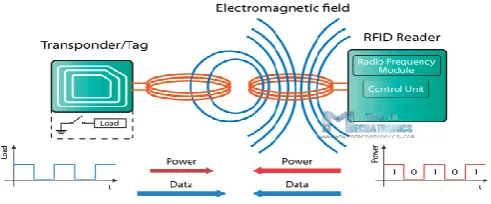
Figure 3.1: RFID Working Principle
RFID Working
all tags tuned to that frequency that are present in the RF field.
Tags receive the signal with their antennas, and selected tags respond by transmitting their stored data. The tag can hold many types of data about the item, such as its manufacturer, product number, serial number, configuration instructions, what time the item traveled through a certain zone, even temperature and other data provided by sensors.
The interrogator receives the tag signal with its antenna, decodes it and transfers the data to the host computer system.
RFID tags can be attached to virtually anything – from a semi tractor, to a pallet, to a case, to an item on a store shelf. If multiple tags are present in the field, more efficient RFID implementations have anti-collision algorithms, which determine the order of response so that each tag is read once and only once.
GSM Communication
GSM (Global System for Mobile Communications, originally Groupe Spécial Mobile) is a standard developed by the European Telecommunications Standards Institute (ETSI) to describe the protocols for second-generation digital cellular networks used by mobile devices such as tablets.
The network is structured into a number of discrete sections:
Base station subsystem – the base stations and their controllers explained.
Network and Switching Subsystem – the part of the network most similar to a fixed network, sometimes just called the "core network".
GPRS Core Network – the optional part which allows packet-based Internet connections. Operations support system (OSS) – network
maintenance.
Figure 3.2: GSM Architecture
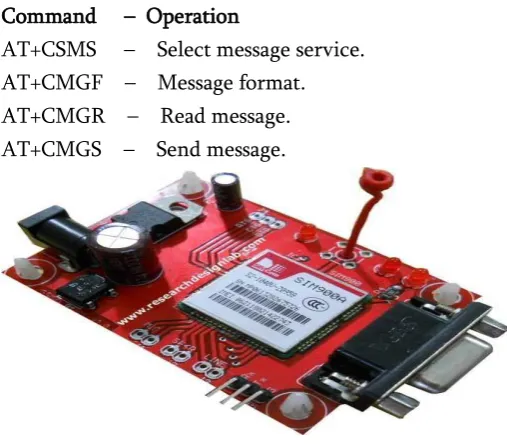
Mobile communication is an emerging technology these days. GSM is the acronym for Global System for Mobile Communication. GSM module is wireless modem that transmits data using radio waves. GSM architecture is similar to the mobile architecture. GSM modems are generally used in many electronic applications and they are required to interface with the microcontrollers. The following AT commands are frequently used to control the operations of GSM modem.
Command – Operation
AT+CSMS – Select message service. AT+CMGF – Message format. AT+CMGR – Read message. AT+CMGS – Send message.
Figure3.3: GSM Module
IV.
RESULTS AND DISCUSSIONBlock Diagram
STEP DOWN TRANSFORM
ER
BRIDGE RECTIFIER
CAPACITOR FILTER
VOLTAGE REGULATOR
ATMEGA162 MICROCONTROLLER
MAX 232
GSM MODULE LCD(16X2)
RFID READER
GPS MODULE
CRYSTAL OSCILLATOR
RESET
KEYPAD (5X1)
SWITCH
Figure 4.1. Block Diagram of Transmitter
GSM RECEIVER
MAX232
MOBILE
Figure 4.2. Block Diagram of Receiver
The aim of this project is to design an RFID Technology based Attendance System using 8051 microcontroller, in which the attendance of students or employees is automatically recorded with the swipe of a card. The working of the project is explained here. When this circuit is powered ON, initially the microcontroller will display the message as Swipe the card on the LCD display. When the RFID reader detects the ID card, it will send the unique card no to the microcontroller via serial terminal. With the help of suitable programming, we need to compare the received card no. with the numbers that are already stored in the microcontroller or any database. Once, if any of these numbers are match with the received
card no., then the corresponding name stored in that no. is displayed on the LCD display and also the attendance for the name stored in the corresponding number is marked. By pressing the button, the attendance recording will be closed and the details are displayed on the LCD repeatedly until the microcontroller has been reset.
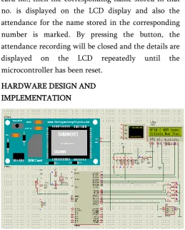
HARDWARE DESIGN AND IMPLEMENTATION
Figure 4.3. Circuit Diagram of Proposed System
The hardware used in t he prototype include the following
1) Power Supply 2) Transformer 3) Bridge rectifier 4) Voltage Regulator 5) Filter
6) ATMEGA162 Microcontroller 7) LIQUID CRYSTAL DISPLAY (LCD) 8) GSM AND GPS
VERIFICATION AND TEST RESULTS
Figure 4.4 : Proteus Simulation of Proposed System
Figure 4.5 : Hardware Implementation of Proposed System
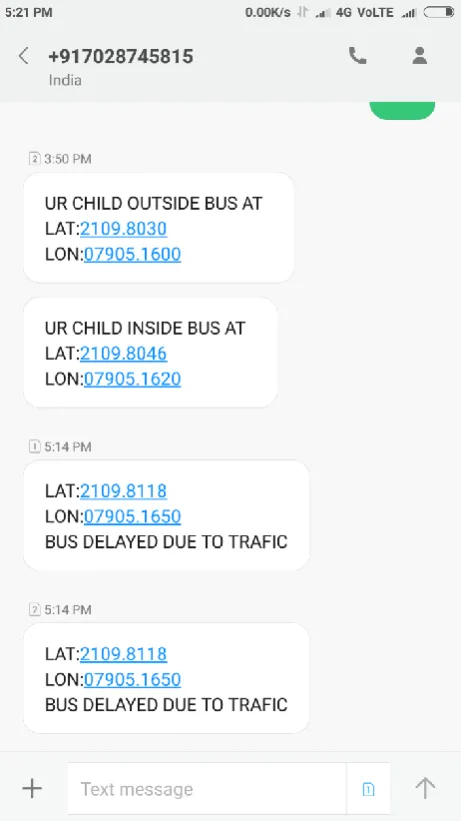
Figure 4.6 : Screen shots of the messages forwarded by the GSM Modem
V.
CONCLUSION AND FUTURE WORKmobile phones and then using the mobile phones GPS (Global Positioning System) the location of the student can be known all over the place and not only the campus. The same ID card can also be used for other functionality of the university like the library card for issuing of books and for example the exam identification card. In this work we have been able to implement a fully functional prototype which is capable of reading the RFID tag and identify it and forwarding the details on the registered number through the GSM Modem
VI.
REFERENCES[1] H. Wegleiter, B. Schweighofer, et al. (2011). "Automatic Antenna Tuning Unit to Improve RFID System Performance." IEEE Trans. on Instrumentation & Measurement, 60 pp.2797-2803.
[2] X. Yao, K. Sungwook, et al. (2009). "Optimum ASK Modulation Scheme for Passive RFID Tags Under Antenna Mismatch Conditions." IEEE Trans. on Microwave Theory & Techniques, 57, pp. 2337-2343
[3] X. Zhu, S. K. Mukhopadhyay, H. Kurata. (2012). "A Review of RFID Technology and its Managerial Applications in Different Industries."J. Eng. & Techn. Management 29, pp. 152-167.
[4] K. Finkelzeller. (2010). “RFID Handbook: Fundamentals and Applications in Contactless Smart Cards, Radio Frequency Identification and Near-Field Communication”. 3rd Ed., Wile. [5] J. S. Lee, Y.W. Su, C. C. Shen (2007). “A
Comparative Study of Wireless Protocols: Bluetooth, UWB, Zigbee and Wi-Fi”, 33rd Annual Conference of the IEEE Industrial Electronics Society, pp. 46-51.
[6] Qiu Jinghui Sun Bo You Qidi, “Study on RFID Antenna for Railway Vehicle Identification”, 6th International Conference on ITS Telecommunications Proceedings, 2006.
[7] A.A.Pandit, Jyot Talreja, Ankit Kumar Mundra, “RFID tracking system for vehicles (RTSV)”, First International Conference on Computational Intelligence, Communication Systems and Networks, 2009.
[8] Xiaoqiang Zhang, Vasileios Lakafosis, Anya Traille and Manos M. Tentzeris, “Performance Analysis of FastMoving RFID Tags in State-of-the-Art High-speed Railway Systems”, IEEE International Conference on RFID-Technology and Applications, 17 - 19 June Guangzhou, China, 2010.
[9] Md. Aminul Islam, Yixian Yap, Nemai Karmakar and A K M Azad, “Orientation Independent Compact Chipless RFID Tag”, IEEE International Conference on RFID -Technologies and Applications (RFID - TA) 2012. [5] Y. F. Weng, S. W. Cheung, T. I. Yuk, and L. Liu, “Design of chipless UWB RFID system using a CPW multiresonator”, IEEE Antennas and Propagation Magazine, vol. 55, no. 1,pp 78-82, February 2013.