Water Utility Decision Support through the Semantic Web of Things
Shaun Howella, Yacine Rezguib, Thomas Beachc
BRE Institute of Sustainable Engineering, 52 The Parade, Cardiff, CF24 3AA
aPh.D. Candidate, BRE Trust Centre for Sustainable Engineering, CardiffUniversity, Cardiff, UK. Email: HowellSK5@cardiff.ac.uk bProfessor, BRE Trust Centre for Sustainable Engineering, CardiffUniversity, Cardiff, UK. Email: RezguiY@cardiff.ac.uk
cPh.D., BRE Trust Centre for Sustainable Engineering, CardiffUniversity, Cardiff, UK. Email: BeachTH@cardiff.ac.uk
Abstract
Urban environments are urgently required to become smarter. However, building advanced applications on the Internet
of Things requires seamless interoperability. This paper proposes a water knowledge management platform which
extends the Internet of Things towards a Semantic Web of Things, by leveraging the semantic web to address the heterogeneity of web resources. Proof of concept is demonstrated through a decision support tool which leverages
both the data-driven and knowledge-based programming interfaces of the platform.
The solution is grounded in a comprehensive ontology and rule base developed with industry experts. This is
instantiated from GIS, sensor, and EPANET data for a Welsh pilot. The web service provides discoverability, context,
and meaning for the sensor readings stored in a scalable database. An interface displays sensor data and fault inference
notifications, leveraging the complementary nature of serving coherent lower and higher-order knowledge.
Keywords: Water management, Decision support tool, Interoperability, Big data, Ontology, Semantic Web, Internet
of Things, Smart water networks
1. Introduction
In order to tackle sustainability and economic challenges through ICT, urban environments, including the water sector, are undergoing a transformation towards smart systems through the use of web-enabled sensors, analytics
software, and decision support tools. Smart water networks have been noted to promote efficacy, efficiency, and resilience of water infrastructure (CTRL+SWAN, n.d.; Mutchek and Williams, 2014; Thompson and Kadiyala, 2014). However, as with fields such as smart grids and smart cities, the application of ICT in the water value chain is restricted
due to an inability to share data and knowledge, and hence interoperate, across the people and software components
involved (EIP Water, n.d.). This has limited the impact of advanced applications such as optimisation engines, artificial
intelligence, and semantic inference. Network operators need modern decision support tools which empower them to
make optimal decisions based on extensive data sources and relevant insights, and this interoperability challenge is
increasingly pertinent (Curry et al., 2014).
In smart grids, this has been stated by IEEE to occur due to three main issues: lack of machine communication
Com-mittee et al., 2011). In the ‘smart water’ domain, the same core issues have restricted the utility and hence prevalence of ICT penetration. Notably, a recent report from the ICT4Water cluster of EC FP7 projects highlighted the need for
standardised models to address the issue of interoperability in the smart water domain (Vamvakeridou-Lyroudia et al.,
2015) and specifically indicated the importance of ontologies as a means to maintain semantic clarity and integrate
knowledge. This leads to a clear precedent in the smart water domain to develop common communication protocols,
data models and semantic vocabularies.
The Internet of Things is addressing the need for interoperable communication protocols, and much progress has
been made in the past 5 years, towards enabling device discoverability and message exchange. However, beyond the
requirement for applications to receive data, they must be able to consume and utilise it correctly with confidence,
which requires a thorough understanding of its context, meaning, and provenance. This requires a robust approach
towards semantic interoperability, and achieving this goes beyond the presently observed Internet of Things, through a convergence with the semantic web. This has been termed the Semantic Web of Things (SWoT), with the key
difference being a focus on application-layer interoperability, as opposed to protocol-layer interoperability (Calbi-monte et al., 2014). SWoT therefore promises to support advanced applications such as artificial intelligence, where
data semantics must be explicitly machine interpretable in order for automated machine-to-machine communication
to be sufficient for reliable data utilisation. These explicit semantic statements are typically collated into semantic models, which create a shared understanding of the domain and a shared method of representing data and their
mean-ing. Within this remit, ontologies are the most expressive option, but are also the most complex, in terms of human
comprehension and computational complexity. Critically, ontology based models also allow the use of inference to
produce new knowledge about a system beyond what has been explicitly stated.
This paper proposes that fostering a Semantic Web of Things will unlock vast potential in the smart water domain, by robustly addressing the interoperability challenge which has been noted as responsible for 40% of the value of IoT
systems (James Manyika et al., 2015). The paper therefore presents a knowledge-based data and inference platform,
and an example decision support tool, which demonstrate the value of the approach. The knowledge management
platform couples a scalable time-series database with a semantic knowledge base, empowered by SWRL rules and an
accompanying inference engine. This is grounded in a comprehensive domain ontology which describes not only the
sensor data and metadata, but also the systemic context of the data, based on a socio-technical system model of the
water value chain. This model federates and extends typical GIS schemas, product descriptions, and expert knowledge
as an OWL ontology. The ontology is then instantiated through a semi-automatic process, supporting the integration
of legacy systems. A key novelty of the approach is the semantic rule base which integrates expert domain knowledge and use case specific heuristic rules with the knowledge-based solution. This is accomplished with real world data
from both clean and wastewater networks for a pilot site in Wales, within the context of an EC FP7 research project,
entitled ‘Water analytics and Intelligent Sensing for Demand Optimised Management’ (WISDOM).
The value of the hybrid semantic approach is demonstrated through a decision support tool which integrates a
The use case of ‘alert impact prediction’ was chosen, whereby a problem such as a blockage occurs in the network, and the decision maker needs to evaluate the impact of the incident on the network and its end-users, within the utility’s
business context. The application therefore uses semantic inference to predict the affected network components, and allows the user to interrogate the issue by viewing dynamic and static data about the network and problem. This
requires an integrated presentation of predicted, static, and dynamic data, in a manner suitable to the expert decision
making process. By highlighting the value of leveraging both the knowledge-based, and data-driven programming
interfaces of the platform, the decision support tool serves as evidence towards the value of the Semantic Web of
Things.
The paper therefore addresses the following primary research question: does a decision support system grounded
in IoT and semantic web provide added value over rule based systems currently used in the sector and those observed
in literature?
The overarching methodology adopted is that of action research, whereby the researcher works with the
stakehold-ers of a target system to both solve an immediate challenge and generate knowledge from the process and outputs.
This involves an iterative learning approach of defining the problem, specifying a proposed solution, building and
testing a proposed solution, then reflecting and learning from the iteration. Such an approach allows agility through
frequent adaptation, and promotes high-quality outputs through transparency and regular expert review. As such, this
paper couples the specification, development, and testing of each of the various components investigated towards
answering the stated question.
The rest of the paper proceeds by discussing background concepts and related work in section 2, then section 3
provides an overview of the proposed solution, and section 4 presents the knowledge management platform in detail.
The benefit of the approach is demonstrated through an example semantic inference use case built on the platform in section 5, and section 6 presents a decision support tool which leverages the coherent lower and higher-order
knowledge served by the platform’s programming interface. Section 7 then discusses the work conducted and offers a perspective on the future of knowledge management in smart water.
2. Background
2.1. Smart Water and Utility Decision Support Tools
The application of ICT and cybernetics principles to the water sector has grown significantly in recent years
through the notion of smart water networks (Amir Cahn, 2013; Mutchek and Williams, 2014; Sensus, 2012). These
aim to use intelligent sensing (Allen et al., 2013), optimisation (W Zhao et al., 2016), and decision support (Schenk, 2010) to operate clean and waste water networks and assets in a more efficient, sustainable and reliable manner. A cluster of European Commission Seventh Framework Programme (EC FP7) research projects, ICT4Water, has been
formed to investigate various aspects of this proposition (ICT4Water, 2015), and the European Innovation Platform
The smart water networks forum (SWAN) is serving as a nucleus for this trend, and has proposed a framework for smart water networks (Amir Cahn, 2013) consisting of several layers: physical, sensing and control, collection and
communication, data management and display, and data fusion and analysis.
One key impact scenario identified by SWAN is intelligent pressure management to reduce leakage and energy
consumption whilst improving network resilience. Recent work has demonstrated a 12.5% leakage reduction through
intelligent pressure reduction based on an EPANET model (Babel et al., 2009), and this was conferred by another
work (Creaco et al., 2016) which minimised energy consumption whilst optimising network pressures. Another work
utilised a cloud-based machine learning approach to leakage management (Mounce et al., 2015), and a platform has
been developed which aims to integrate ICT with water networks to promote reliable and resilient resource
man-agement, whilst reducing energy consumption (Lee et al., 2015), based on a cyber-physical approach. However,
implementing these smart water solutions in practice requires pervasive interoperability, as highlighted by the recent SWAN report on communication in smart water (Andreas Hauser et al., 2016).
2.2. Supporting Smart Systems through the Internet of Things
The role of IoT in smart water has been increasingly noted (Wong and Kerkez, 2016; Robles et al., 2015),
re-sulting in various reference architectures and platforms. It is noteworthy that (Robles et al., 2015) highlights the role of semantics and knowledge-oriented interoperability, although the authors only offer a model of a system’s ICT components, as opposed to the underlying socio-technical system, although the paper does stress the value of adding
semantics to the work presented.
In the broader smart city field, many examples exist of IoT platforms aiming to coordinate data management
(AL-MANAC, n.d.; Kolozali et al., 2014; Lea and Blackstock, 2014; RERUM, n.d.). The CityPulse project (CityPulse,
n.d.) for example, emphasises scalable IoT stream processing, and includes semantic tagging of streams, but this is
based only on a simple ontology describing the domain of data and event streams, rather than contextualising the
data through a model of the target socio-technical system. The ALMANAC project (ALMANAC, n.d.) proposed a
service oriented architecture for the collection and analysis of near real time information, and again boasted semantic
interoperability. The ALMANAC platform went beyond the semantic modelling conducted in CityPulse to include domain concepts, such as their ontology for water applications (ALMANAC, n.d.), but this only described 6 types of
object, so again lacks true domain contextualisation. The RERUM project proposed an IoT framework, but
empha-sised its security and privacy aspects (RERUM, n.d.); this again utilised a semantic model, but it only described the
cyber-physical nature of IoT systems, and not the underlying socio-technical system, similar to CityPulse. Finally,
the recent Hypercat standard specifies a lightweight file format and API for discovering and accessing IoT resources
(BSI, 2016).
2.3. Beyond the Internet of Things to a Semantic Web of Things
The common emphasis on semantics in the most recent IoT platforms is noteworthy, but fails to deliver the
domain. The nature of IoT and semantic web convergence has recently been driven by the W3C Web of Things Work-ing Group, which is developWork-ing a suite of standards to overcome silos in the industry, includWork-ing a ’ThWork-ing Description’
model: a vocabulary for describing Things, with a default serialization of JSON-LD (W3C 2017). This demonstrates
a clear appetite in the industry for development in this direction of convergence. The long-term ambition of such work
is to closely integrate time-series data (which a great deal of IoT data is), with RDF data in a homogeneous manner.
However, this represents a significant ongoing research challenge in its own right, whereas significant value can be
derived in the short-term from using these technologies in a loosely-coupled manner, which allows mature tools to be
leveraged alongside each other without fundamental changes, which is a beneficial compromise.
The value of the convergence of the semantic web and IoT has been noted by many authors (Gyrard et al., 2014;
Jara et al., 2014; Pfisterer et al., 2011; Sahlmann and Schwotzer, 2015), although they express different perspectives on this new field. These works share an emphasis on powerful interoperability through ontologies and open models. Jara et al. (Jara et al., 2014) present their survey and vision towards a SWoT, highlighting interoperability at a greater
level of abstraction as an evolution of IoT, through high-level modelling of real world entities. Gyrad et al. (Gyrard et
al., 2014) also present their vision of SWoT, but instead emphasise it as an evolution, through semantic interoperability
across domains, and again through greater domain knowledge modelling. The earlier work of Pfisterer et al. (Pfisterer
et al., 2011) also proposed SWoT with an emphasis on modelling real world entities, but framed the work as an
evolution of semantic sensor networks. Finally, (Sahlmann and Schwotzer, 2015) adopts a novel stance on SWoT,
whereby web-enabled things exchange micro-ontologies, as an extension of MQTT and CoAP. This proposes an IoT
revolution through fundamental change of its enabling technologies, rather than integrating a higher-order knowledge
layer above existing approaches.
One example which acknowledged the role of higher-order knowledge management in the water domain is (Stew-art et al., 2010), where a knowledge-based system was developed for the web which enabled consumption knowledge
to be elicited from smart metering data. Also highly significant, the WatERP project proposed an agent-oriented ICT
platform to enable supply and demand matching in water networks, and used a domain ontology alongside a data
warehouse to manage the solution’s data (WatERP, 2013), although the ontology is still relatively simple compared to
those utilised in other domains such as energy and building information modelling.
As well as promoting semantic interoperability, inference represents a key advantage of ontological modelling; that
new knowledge can be created from explicit knowledge. That is to say that beyond what is manually or automatically
instantiated of a domain model, it is possible to infer new knowledge based on the existing statements made in the
domain model. This relies on the ‘open world assumption’ which ontological modelling utilises. This assumes that anything which is not stated may be true, as opposed to conventional object-oriented modelling which assumes that
anything which is not stated is not true. The role and mechanisms of semantic inference have been well explained
recently (Shu et al., 2016) in the context of data validation. Based on such a semantic inference capability, an inference
2.4. Semantics in Smart Cities and Smart Water
As a recent challenge, ontological models in the smart water field are sparse, although some relevant examples
are observed. Firstly, in the broader smart city field, the ISO/IEC Joint Technical Committee’s report on smart cities (ISO/IEC JTC1, 2014) highlighted the need for ontologies. IBM developed the SCRIBE smart city ontology 5 years ago (Rosario Uceda-Sosa et al., 2011), commenting on a lack of available ontologies, and stable OWL tools. Their
ontology paved the way for formal descriptions of city services, events, metadata, and abstractions. A smart city
ontology termed ‘Knowledge Model 4 City’ was developed in (Bellini et al., 2014), with a focus on public transport
and mobility, and also included a mapping to sensor concepts. However, this simple ontology seemed to only facilitate
the query of public transport data by SPARQL. The SEMANCO project developed a large smart city ontology in
OWL DL-Lite for the purpose of data integration (Nemirovski et al., 2013), resulting in 592 classes. The SEMANCO
ontology appears to be intended for the exchange of static data in the planning phase of urban areas though, given the lack of sensor concepts and dynamic data provision. It could therefore contribute to an upper ontology which
links ontologies in each sector, as operational data and semantics are closely coupled to their target system and
industry. The CityGML standard (Grger and Plmer, 2012) formalises concepts and relationships relevant to geospatial
knowledge in cities, and some semantics as to the nature of objects and spaces in cities, but in an insufficient manner for interoperability of operational smart city data across verticals. Finally, BSI:PAS 182 (BSI, 2014) proposes a high
level smart city ontology, which serves as an important step, albeit as a ‘lowest common denominator’ approach,
which hence captures little semantic depth.
In the smart water field, high-order semantic interoperability is only being recognised as a challenge very
re-cently, in part caused by the growth of IoT and smart water networks. Attention is increasingly being paid to this
challenge though, with an ongoing cluster of EC research projects, ICT4Water, highlighting the importance of se-mantic modelling (ICT4Water, 2015). The most relevant existing water ontology is that developed in the WatERP
project (WatERP, 2013), which models water balance concepts from the clean water network at a high level.
An-other very relevant model is the semantic water interoperability model (SWIM) (Reynolds, 2014), which formalizes
a description of water sector devices such as sensors, pumps, reservoirs and valves. As well as this, Waternomics,
another ICT4Water project, has developed a linked data model (Curry et al., 2014), and a waste water treatment plant
ontology was observed in the literature (Sottara et al., 2014). Also, several examples of water ontologies have been
identified in the literature which were not specifically for the purpose described. Most notably are the works related to
the CUAHSI Hydrologic Information System (CUAHSI, 2008; Huang et al., 2011; Horsburgh et al., 2009), SWEET
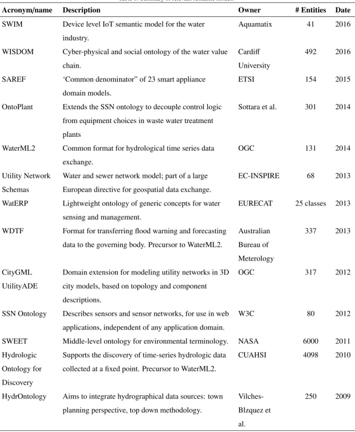
(SWEET, n.d.) and HydrOntology (Vilches-Blzquez et al., 2009). These ontologies, and several others, are compared in Table 1. From Table 1, it is clear that whilst significant semantic modelling has been conducted, this is mainly
aimed at the field of earth sciences rather than considering man-made water infrastructure artefacts, and is hence not
sufficient for the challenge described. The INSPIRE water and wastewater network data specifications (INSPIRE Thematic Working Group Utility and Government Services, 2013) are very relevant to the smart water domain, but
formali-sation available, with the other INSPIRE ‘thematic areas’ being less relevant from a utility network perspective. The WatERP ontology is very relevant and has significant overlap with the scope of the current work, although it is not
comprehensive enough for the identified challenge.
It is evident that little effort to date has focused on the challenge identified; most efforts have been targeted at the earth science domain rather than the man-made water value chain, which only has a small number of limited
ontologies. Semantic modelling in this specific domain has been raised as a critical issue (ICT4Water, 2015), and is
widely acknowledged as such in the neighbouring fields of smart grids and smart cities. There is a significant gap
in the field of capturing in-depth knowledge regarding the technological, network, social, sensory and ICT artefacts
involved in water management decisions in a water value chain. Also, there is a significant gap in leveraging the value
of semantic inference, and of demonstrating the value of the Semantic Web of Things through powerful interoperable
platforms and applications.
3. Overview and System Architecture
This section presents the ICT platform developed, from the sensors and actuators to browser-based interfaces for
utility experts and domestic end-users. The requirements engineering process and outputs at the system level are
discussed first, then the overall architecture is discussed. Then, a description of the software implementation of the
knowledge management components is offered, and finally a focus on the inference and rule engine integrated into the knowledge management service.
3.1. Requirements Elicitation and the Need for Semantics
A comprehensive requirements engineering methodology was conducted for the overall software solution, which was then decomposed for the elicitation and refinement of individual component requirements. This followed a typical
iterative analysis and design approach alongside industry experts, which is now described briefly before the outcomes
pertinent to this paper are discussed.
The first stage of the process was to gather knowledge about the domain, target systems, and intended value
proposition of the overall software solution. Following this, formal modelling was conducted of the business
pro-cesses involved in the target system, and scenarios for the use of ICT within these were developed. Next, software
requirements were produced for the overall software solution, following use case specifications and sequence
dia-grams. These requirements were then iterated alongside domain experts, and the previously developed scenarios, in
order to ensure a comprehensive set of requirements was produced. This specification therefore bounded the scope of the software development task, by defining what it should be able to solve, and what is out of scope. This
al-lowed a system architecture to be curated, and the requirements were then decomposed into separate requirements for
each component. For the knowledge management service, this was then refined further alongside the development
of knowledge modelling requirements and an observed need for domain expert engagement and buy-in regarding the
Table 1: Summary of relevant semantic models
Acronym/name Description Owner # Entities Date
SWIM Device level IoT semantic model for the water
industry.
Aquamatix 41 2016
WISDOM Cyber-physical and social ontology of the water value
chain.
Cardiff University
492 2016
SAREF ‘Common denominator” of 23 smart appliance
domain models.
ETSI 154 2015
OntoPlant Extends the SSN ontology to decouple control logic
from equipment choices in waste water treatment
plants
Sottara et al. 301 2014
WaterML2 Common format for hydrological time series data
exchange.
OGC 131 2014
Utility Network Schemas
Water and sewer network model; part of a large European directive for geospatial data exchange.
EC-INSPIRE 68 2013
WatERP Lightweight ontology of generic concepts for water
sensing and management.
EURECAT 25 classes 2013
WDTF Format for transferring flood warning and forecasting
data to the governing body. Precursor to WaterML2.
Australian Bureau of Meterology 337 2013 CityGML UtilityADE
Domain extension for modeling utility networks in 3D
city models, based on topology and component
descriptions.
OGC 317 2012
SSN Ontology Describes sensors and sensor networks, for use in web applications, independent of any application domain.
W3C 80 2012
SWEET Middle-level ontology for environmental terminology. NASA 6000 2011
Hydrologic
Ontology for
Discovery
Supports the discovery of time-series hydrologic data
collected at a fixed point. Precursor to WaterML2.
CUAHSI 4098 2010
HydrOntology Aims to integrate hydrographical data sources: town
planning perspective, top down methodology.
Vilches-Blzquez et
al.
The requirement engineering process produced outputs at each stage, including business process diagrams, soft-ware use cases, sequence diagrams, scenario descriptions, meta-requirements, softsoft-ware requirements, competency
questions, non-functional ontology and process requirements and a semi-automated extraction of domain vocabulary.
Following this extensive process, several observations led to the decision to pursue a system which represented a
con-vergence of IoT, semantic web, artificial intelligence, and rule-based systems. Critically, the need for an ontological
grounding for the solution emerged from the following requirements, for which existing approaches were deemed
unsuitable:
• The knowledge modelling component should aim to be application agnostic; it should have value outside of the
initially intended system.
• The supported data and underlying domain perspectives should be easily extensible and adaptable.
• It should be possible to modify the underlying data structure easily without taking the service offline.
• It should be possible to query over multiple datasets simultaneously.
• It must be possible to integrate multiple ICT systems which exhibit semantic heterogeneity.
• It must be simple to integrate a rule-based approach with the knowledge base.
The classes of domain problems which are directly within the scope of the software are expressed through the scenarios
which were a key outcome of the requirements engineering process. Whilst these have extensive descriptions beyond
the scope of this paper, they can be broadly understood from the knowledge management modules perspective as follows:
• Integrating domestic smart meter and user engagement data with supply-side data to provide analytics to both
sides
• Integrating the visualisation and API access for utility GIS data, telemetry data, asset data and metadata
• Supporting the discovery and use of sensor data for predictive analytics and optimisation, including pumping
optimisation, CSO spill prediction, and leakage detection
• Providing knowledge-based analytics into the behaviour of the system, using static data and timeseries values
at predefined key times and levels of aggregation (e.g. previous single timestep, average of last 10 timesteps,
max of last 50 timesteps).
As well as understanding which problems the software is designed to solve, it is relevant to state potential capabilities
and problems which are out of scope:
• Generic stream-based RDF reasoning
• Complex hydraulic flow modelling
• Fully automated integration with legacy systems or data
Further, several problems were not directly considered, but the system could be useful in tackling them with little
additional work:
• Complex pressure management scheme experiments will not be conducted
• Business strategy level analytics will not be considered, as the focus is on operational decision making
• Maintenance prediction and prioritisation will not be considered
• Remote actuation will not be directly experimented
In a broad sense, the knowledge management platform is capable of solving problems primarily related to the
in-tegration of knowledge sources, knowledge-based reasoning (similar to expert reasoning), and the discovery and
contextualisation of data and Things. The system improves the access to, and utilisation of, timeseries sensor data by
external analytics, but does not itself provide analytics features over full streams of high-velocity timeseries data nor
use traditional hydraulic models.
3.2. System Architecture
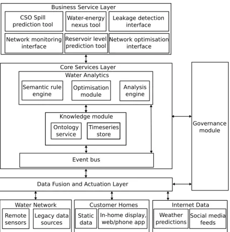
The ICT platform utilised a service-oriented architecture to coordinate data and knowledge management in a
scalable manner above a communication interoperability layer, to expose a comprehensive range of information to
the business services layer. This is shown in Figure 1 below, which also illustrates the role of the governance service
across the core platform services.
3.3. Knowledge Management Software
The knowledge management service included a semantic web service, a time series database, a resource catalogue
API, and a Drools rule engine, as well as a RESTful API for querying and updating the knowledge base. The functional
architecture of the knowledge management service is shown in Figure 2 below.
The first noteworthy component of the knowledge management service was the triple store and SPARQL endpoint,
which stored static knowledge about the socio-technical system, and contextualised references to the dynamic data stored in the time series database. This was an instantiation of the domain ontology described in section 4. The triple
store was updated by subscribing to messages from the event bus, such that it always represented the latest state of the
water value chain. The ontology was stored in a persistent triple store which used the Apache Jena libraries for query
and update functions. The server exposed a simple RESTful API and a standard SPARQL endpoint, where the former
Business Service Layer CSO Spill
prediction tool Water-energynexus tool
Leakage detection interface Network monitoring
interface
Reservoir level
prediction tool Network optimisationinterface Core Services Layer
Water Analytics Semantic rule
engine Optimisationmodule
Analysis engine
Knowledge module
Event bus
Data Fusion and Actuation Layer Water Network Remote sensors Legacy data sources Static data Customer Homes In-home display, web/phone app Internet Data Weather
predictions Social mediafeeds Governance module Ontology
service Timeseriesstore
Figure 1: Functional architecture of the proposed ICT solution
Knowledge Management Service Ontology Service Apache Jena RDF database SPARQL endpoint Hypercat service Water network query wrapper Resource catalogue Static water knowledge Drools rule engine Ontology API Inference API
Pellet reasoner Inference API
SPARQL endpoint Resource catalogue Static water knowledge KairosDB store Event logging service Analytics and business services Event bus Broker Gov-Plugin Data acquisition layer Timeseries endpoint Governance CAS server
Figure 2: Knowledge management UML component diagram
order to retrieve static data, applications query the triple store directly. In order to discover dynamic data, or to gain
context for known data, applications could query the ontology via the SPARQL endpoint. For applications to retrieve
dynamic data, they utilised the time series database portion of the API, which adopted a coherent structure and naming
The time series database utilised the KairosDB libraries (KairosDB, n.d.), which are built on the Apache Cassandra database solution. This allows fault tolerant and scalable data storage and retrieval, and is hence better suited for
handling high volumes of raw, well structured, data than a triple store.
Sensor data integration had three aspects: centralisation, pre-processing and storage, and integrated discovery and
metadata description. Centralisation of the sensor data involved wireless sensors publishing observations to an Apache
Kafka event bus, either directly or via a gateway at some sites. Data streams were subscribed to directly by some
real-time applications, and also by the internal knowledge management module, where the observation real-timestamps and
values were then sent to the kairosDB time series service, and also the ontology service. The Kairos service then
undertook basic pre-processing before storing observations against an internal sensor ID, and the ontology service
updated its ’latest observation value’ accordingly. The APIs of these services could then be used across all of the
sensors in an integrated way. Finally, the sensor metadata and semantic data was integrated within the ontology service, which was linked with the kairosDB time series data through the internal sensor ID, and cataloguing of the
sensors was achieved through the Hypercat endpoint.
The inference solution integrated the Pellet reasoner for simpler rules and OWL-based inference, with a separate
Drools engine for managing more complex SWRL rules. This approach was chosen as Drools was found to offer better performance and reliability during testing. Therefore, at each timestep, the Drools engine re-evaluated the triple store
against the rules, and updated the triple store accordingly with any new inferred knowledge. The use of Drools within
an ontology-driven application has been demonstrated previously (Sottara et al., 2012) within a waste water treatment
plant, albeit not in an IoT platform setting.
3.4. Resource Discoverability and Interoperability Signposting
To promote automated and simplified manual discoverability of water network virtual resources, and to leverage
recent developments in the IoT field, the knowledge-based solution was integrated with the recommendations of
the Hypercat standard (Hypercat Limited, 2016), due to its recent community adoption and standardisation. This
mandated the modelling and alignment of the simple Hypercat metamodel as an OWL ontology with the water value
chain ontology produced. It was also chosen to support the Hypercat RESTful API through a simple wrapper around the JENA ARQ query engine utilised as shown in Figure 2. This wrapper converted Hypercat queries into SPARQL
SELECT queries, so as to retrieve resource descriptions from the knowledge base via the Apache Jena ARQ library.
After executing the query, the wrapper then converted the resulting object into a Hypercat compliant catalogue object.
Provisioning for the retrieval of resource information via the Hypercat approach allowed for simpler
discover-ability, owing to the accessible nature of the Hypercat specification. This also supported greater reusability of the
developed solution, through applications developed for the Hypercat ecosystem. By querying the Hypercat API of the
knowledge-management service, a catalogue was returned describing all of the active sensors on the network and the
service’s endpoints, and this was updated automatically as entities were added or removed.
installed in the target systems than the SPARQL endpoint. Specifically, the Hypercat-enabled data included the location, type, URI, API type, latest reading value, latest reading time, unit of measure, name of the sensor, and a
textual description. Also, a pilot-site agnostic upper catalogue was exposed which provided discoverability of the
available knowledge bases and accompanying pilot sites. As the sensor readings were hosted on a KairosDB server,
this ‘signposting’ would allow a developer to integrate the available data into an application with far less difficulty. For a full semantic description of the sensor, sensing method, and physical contextualisation of the data, the developer
could then query the full knowledge base via the SPARQL endpoint if desired. Whilst the sensors were the only
entities which were Hypercat-enabled, it would have been possible to Hypercat-enable the entire knowledge-base, but
this was not required for the use cases considered likely.
3.5. Semantic Inference and Rules Engine
The inference and rule engine was closely coupled with the knowledge management software, due to their related
functionality, and the need for the inference to maintain pace with updates to the knowledge base. This relied on a
combination of the native Apache Jena inference engine, the Pellet engine, and the Drools rule engine; the latter of
which handled the triggering of business rules.
Apache Jena natively supports 4 types of reasoner based on the architecture: transitive reasoner, RDFS rule reasoner, OWL/Lite reasoners, and generic rule reasoner (Apache Jena - Jena Ontology API, n.d.). These increase in inference capability from the transitive reasoner to the generic rule reasoner, although even the most capable of
the Jena reasoners typically achieves less inference than the Pellet reasoner, due to Jena being RDF based and Pellet
considering the entire conjunctive query (Complexible, n.d.).
As the Jena API integrates the Pellet inference engine (Complexible, n.d.) with little effort, and the Pellet engine is well regarded for capability and speed, the Pellet reasoning engine was chosen to exploit the maximum potential from
the OWL axioms. Further, Pellet relaxes OWL-DL restrictions on the OWL-Full features, and allows the majority of
SWRL built-in atoms. This meant that Pellet could reason over rules which included maths features and numerical
comparisons, which have been included in the developed SWRL rule set. However, during testing this inference
capability was found to be slower, and less reliable, than the use of a separate Drools engine. The Drools rule engine was incorporated into the platform to augment the inference capabilities of the Pellet reasoner, which achieved
acceptable inference completeness and speeds over native OWL axioms, but not over heuristic business rules.
The Drools rule engine is specifically designed for business rules, and uses forward-chaining and
backward-chaining to infer new knowledge from existing data, with rules stated in either the Drools native language or a decision
table. Drools reasoning is optimised for when x, then y business rules using their PHREAK algorithm; an evolution
of the Rete algorithm, whereas Pellet is optimised for knowledge inference using tableaux algorithms over description
logic axioms. Therefore, the Drools engine is better able to handle a large number of rules, with faster and more
reliable firing of complex rules than Pellet. Also, it is important to note that SWRL limits the kind of rules which can
URI functions. Even moderately complex rules can become difficult for humans to read and write, whereas the Drools Rule Language is comparatively simple to write, and yet is more expressive. Drools also allows more complex pattern
matching within the conditional part of a rule and more complete functionality in the consequence part, including
update, insert, and delete functions. SWRL cannot be used to delete or insert new named entities, modify properties
used in the antecedent, count instances or test negated atoms, due to the monotonic nature of SWRL. Whilst the rules
were formalised in SWRL and converted to the Drools rule language to experiment with a complete semantic web
approach, expressing them in the native Drools language, or a Drools Domain Specific Language (DSL) is an area of
further research.
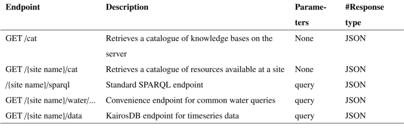
3.6. API Overview and Illustrative Usage
The knowledge management system offered a variety of APIs to support the retrieval of knowledge by tools of varying complexity, as shown in Table 2. This could integrate both knowledge-based applications and data-driven
applications, and could be used at various lifecycle stages. A generic use of these endpoints would be to firstly
discover resources, then retrieve data based on the nature of the client application. A generic process diagram for
using these APIs is illustrated in Figure 3.
Table 2: Implemented knowledge management API
Endpoint Description
Parame-ters
#Response type
GET/cat Retrieves a catalogue of knowledge bases on the
server
None JSON
GET/{site name}/cat Retrieves a catalogue of resources available at a site None JSON
/{site name}/sparql Standard SPARQL endpoint query JSON
GET/{site name}/water/... Convenience endpoint for common water queries query JSON
GET/{site name}/data KairosDB endpoint for timeseries data query JSON
/cat:
Retrieve catalogue of sites (Hypercat object) /{site name}/cat:
Retrieve catalogue of site resources (Hypercat object)
/{site name}/sparql: Retrieve static data (JSON, explicit RDF/OWL semantics)
/{site name}/water: Retrieve simplified (JSON, implicit semantics) /{site name}/data:
Retrieve timeseries sensor data (JSON/WaterML)
As shown in Figure 3, it would be typical for applications to first query the Hypercat endpoint, to determine the online resources. If the application has already determined the available site knowledge bases and endpoints, it may
directly query the site’s Hypercat endpoint to then discover the online sensors at that site. At that point, the usage
of the system would vary depending on the nature of the client application; a simple dashboard for example may
only query the simplified API to determine some common static knowledge about the network and the latest sensor
readings. Alternatively, a more complex application may query the knowledge base directly via SPARQL to retrieve
detailed static data. An application could also query the timeseries endpoint to retrieve dynamic sensor data, and then
query the SPARQL endpoint to retrieve semantic context for the dynamic data, to facilitate its correct use in the client
application. An example which highlights the value of these varied endpoints is provided in section 6.
4. A Knowledge-based Approach to Water Management
This section presents the process and artefacts related to the knowledge-based approach adopted, which includes
the development methodology, the domain ontology and its validation, and the instantiation of the ontology from
legacy data.
4.1. Requirements and Ontology Engineering
The ontology service’s requirements and curation process primarily used the well regarded NeOn methodology
(Prez et al., 2008) for manual curation from existing semantic resources. Minor adaptations were made to this
ap-proach, due to changes in the technological landscape in the past 9 years since the NeOn methodology was published,
such as the growth of the Internet of Things, which has fundamentally shifted the way the internet is used. Also, a key requirement was for the ontology to have value outside of the target system as a benchmark in the field. This
in-volved balancing the knowledge engineering objectives prioritised by NeOn with the software engineering objectives
of the overall IoT project, and the softer requirements from the domain experts of fostering ownership and human
intelligibility.
In order to scope the ontology, a literature review was conducted of the semantic resources in the field, to give
context to the model. Secondly, the software requirements were decomposed further into competency questions,
con-ceptually orchestrated through the project’s scenarios. These were then formed as a set of formal SPARQL queries
which the ontology was required to answer, and which were adapted as the project matured and the role of the
ontol-ogy service became clearer. The initial intent of the ontolontol-ogy was to capture the physical, cyber, and social concepts
relevant to network-level operational management in water utility systems; to unify the knowledge management of geospatial data, domain specific concepts, and IoT metadata. The boundaries of the ontologys scope were also
clar-ified beyond the initial intent by stating those concepts which it would not focus on: natural artefacts, electricity
consumption, non-domestic consumers, the internal operation of water assets, and financial aspects. An indicative
• How much water is domicile X currently consuming?
• What material is pipe X made from?
• How frequently does sensor X report observations?
• Which are the output pipes of asset X?
• How much water is currently in reservoir X?
• Where is asset X located?
• What is smart valve Xs current state?
• What does sensor X measure, in which units, and what was its latest observation?
• Who is the designated manager for asset X?
Following scope formalisation, existing models were manually selected and reworked into a base ontology, which
was extended with domain and project specific concepts and T-Box axioms, to meet the competency questions derived
for each of the project’s impact scenarios. This included the reuse of a typical GIS schema and the extension of
a socio-technical system model (Dam, 2009). The resulting artefact was then collaboratively iterated with water
industry experts towards a consensus until the candidate ontology was deemed an accurate and sufficient description of the water management domain. Following this, further alignments were sought with external semantic resources to
foster interoperability.
4.2. Water Value Chain Ontology
The water value chain ontology modelled the concepts, relationships, properties, datatypes, restrictions, and logic,
in water networks from abstraction to discharge, using OWL constructs. This was grounded in a view of the network
as 3 main interlinked systems: physical, social, and cyber. The ontology therefore captured domain knowledge from
these 3 perspectives, and across each of these 3 perspectives.
The physical water network model was an extension of a typical GIS schema from a water utility, and so primarily
described the physical network assets and their properties. This included objects such as pipes, fittings, manholes,
pumps, and treatment plants, and properties such as pipe diameters, fitting locations, and manhole types. The GIS
schema was extended through abstraction into a metamodel of socio-technical systems, and was also extended with
descriptions of domestic properties, natural water bodies, and physical phenomena and fluid dynamics. The model
fundamentally viewed the physical network as a network of nodes and arcs, with each node potentially also being a
super-node containing a subsystem of nodes and arcs, as in the case of a treatment plant.
The social water network model described the organisations and people involved in the water value chain, such
these organisations. Similar to the physical model, this adopted a 2 level of detail approach, whereby organisations were viewed as supersystems of people, and their relationships and processes. This modelling decision was taken
as it was recognised that organisational-level modelling would be sufficient in many cases, but specifying the person responsible for a specific asset may be required for certain applications. Socio-technical relationships were also
modelled, such as ownership, management responsibility, and regulations.
The cyber water network model described the sensors, actuators, data, and software, in the ICT system which
supports the network’s management. This was accomplished as an extension of the W3C SSN ontology (Compton
et al., 2012), although observations were not stored in RDF; the ontology instead described where these observations
were stored in the timeseries database. This allowed the observations to be contextualised but also stored in a scalable
manner. Typical metadata was described, such as sensing frequency and accuracy, but further systemic context was
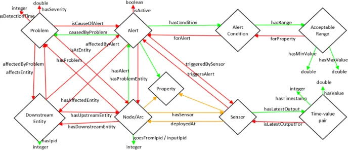
also captured regarding the meaning of the data. Specifically, the nature of the sensed phenomenon and the physical entities being observed were provided with classes and slots for description in the ontology. Cyber-physical
relation-ships were therefore described to formalise relationrelation-ships between sensors, data, time series database fields, network
assets, and fluid dynamics properties. This is illustrated in Figure 4.
The ontology’s grounding in the SSN ontology was facilitated by an adoption of the same upper ontology, the
DOLCE+DnS Ultralite (DUL) upper ontology (Gangemi, n.d.). This integrates the DOLCE Lite-Plus library with the Descriptions and Situations ontology, and simplifies it for practical use. Therefore, the developed ontology uses
similar design patterns to those of the DUL ontology, and hence focuses on the properties (SSN:property) and roles of
the designed artifacts (DUL:DesignedArtifact) which participate in processes (DUL:Process) in the water network, as
well as the agents (DUL:SocialAgent) which control these artifacts, and especially the observations (SSN:observation,
subclass of DUL:Situation) made by sensors, and their resulting information objects (DUL:InformationObject). The majority of the ontology is hence an extension of these classes with subclasses and additional properties, although
concepts related to network topology (i.e. graph theory) and water consumption behavior were also added.
4.3. Ontology Validation
Following the development of the ontology & accompanying software, the requirements were tested against, to evaluate the ontology and the overall solution’s acceptability against initial intentions. This involved a number of
specific workshops with domain and software experts.
The initial, automated check of the ontology’s consistency through the built in Prot´eg´e reasoner was consistently
passed, such that the ontology does not contain contradictory statements. The competency questions were answered by
the ontology after being posed as SPARQL queries. The domain expert validation was conducted separately with the
domain expert partners through one day workshops, and in both cases the ontology’s modelling choices were broadly
validated, the majority of the detailed modelling choices were validated and corroborated between workshops, and
some revisions and extensions were suggested. An additional workshop with the WISDOM partners and external
Figure 4: Key cyber-physical relationships in the water value chain ontology (inverses not shown)
that the ontology was sufficient. The organisation types of these companies are shown in Figure 5.
The ontology was therefore considered by a wide range of stakeholders in the water value chain, most of whom
had little bias towards the project. This offered a broad view on the ontology and hence tested its extent, as well as its detail in areas of the water value chain which the WISDOM partners were not experts in. That consensus was
reached that the ontology represented a shared and sufficient conceptualization of the domain by this group, which was a significant milestone in its validation. Some of the comments from the SIG expert validation session were:
• The ontology addresses the problem of interacting between tools (GIS, SAP, customer data)
• Include alarms as well as sensors
• ‘Governing body’ is also called ‘regulator’
• Include ‘water testing company’
These comments were all used to revise the ontology. The majority of the comments however were advisory
or generic, such as regarding possible future work, rather than required changes in the scope currently addressed.
Examples of these comments were:
• The work could be considered as a type of enterprise service bus
• An ontology is also called a taxonomy
0 1 2 3 4 5
Figure 5: Organizations involved in the validation process
Table 3: Example competency question (prefix statements omitted)
Natural language question:
What is sensor E2000’s current reading?
SPARQL query:
SELECT ?reading
WHERE{
wis:E2000 rdf:type wis:LevelSensor.
wis:E2000 wis:hasLatestOutput ?output.
?output dul:hasDataValue ?reading}
Output (CSV format):
reading
2.00
• Collaboration relationships exist between utilities which share a water resource
Table 3 below presents an example outcome of the competency question testing, showing how the deployment
answers the questions when formalized as SPARQL queries, where the queries were answered in circa 15ms.
4.4. Instantiation through Reuse of GIS and EPANET Data
Following from the domain ontology development, the knowledge base development involved the instantiation of
this domain model at each pilot site. This section presents an overview of the process and outputs of this work, which
resulted in pilot site knowledge bases for both clean and waste water networks at Welsh pilot sites. This work adopts
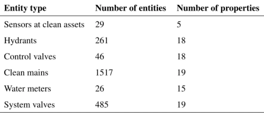
a novel methodology of converting GIS and EPANET data to RDF data through a Python script. Each knowledge
Table 4: Summary of water and wastewater network input data
Entity type Number of entities Number of properties
Sensors at clean assets 29 5
Hydrants 261 18
Control valves 46 18
Clean mains 1517 19
Water meters 26 15
System valves 485 19
beneficial to the targeted use cases. Each knowledge base was produced by reusing existing data from utility company
partners, and then extended manually.
The knowledge bases were instantiated primarily by reusing GIS, sensor, and EPANET data provided by industrial
partners, through a Python script. This was then enriched manually with further sensor and social entity descriptions.
Each pilot sites Abox was kept separate, but could be trivially merged with the Tbox if required, or kept separate until
storage in the triple store. After pre-processing, the Python script used RDF and CSV libraries to parse, build and
output relevant files, by iterating over each line of the input file and creating named entities, data properties, and object
properties as appropriate. The main reused GIS objects were system valves, meters, mains, control valves, hydrants,
asset sensors, conduits, nodes, pumps, sensors and subcatchments as summarised in Table 4 below. In total, these
represented 6 MB of data and resulted in 100k RDF A-box triples, including 10k named entities.
This model transformation converted the data from simple lists of values with implicit semantics, to an RDF
graph based on the developed model, as shown in Figure 6, with the benefits of explicit semantics, high levels of expressiveness, and unique IDs. Where appropriate, the properties themselves are objects with their own sets of
object and data properties; therefore, the meaning is far more explicit and could be reused by other software with
greater confidence in its meaning, hence requiring less investment to ensure successful interoperability.
Expressiveness and extensibility are significant benefits of the semantic modelling approach. For example, the
‘hasMaterial’ property is an object property which connects a pipe to a material, the material can then be described
by properties such as surface roughness, for hydraulic modelling, or fracture toughness, for earthquake resilience
simulation. These examples show respectively that the approach allows greater value to be derived from the initial
data by formally describing it in a machine interpretable manner, and allows extensibility beyond its initial purpose
with little effort. Further, semantic inference over the RDF form of the data allows greater value to be derived from the original data. For example the ‘goesToIpid’ is a datatype property which connects a pipe to an integer, but an SWRL rule was used to infer the knowledge that, given that the integer is the ID of another pipe, the latter is downstream of
Data property assertions:
Pipe_1 hasLength "5.93"^^xsd:double Pipe_1 hasNominalDiameter "6.0"^^xsd:double Pipe_1 isPumped false
Pipe_1 hasIpid 16573054
Pipe_1 hasAbsoluteDiameter "152.0"^^xsd:double Pipe_1 hasUnit "IN"
Data property assertions:
Pipe_2 hasLength "5.43"^^xsd:double Pipe_2 hasNominalDiameter "6.0"^^xsd:double Pipe_2 isPumped false
Pipe_2 hasIpid 2048352
Pipe_2 hasAbsoluteDiameter "152.0"^^xsd:double Pipe_2 hasUnit "IN"
atAsset has individual has subclass hasDownstreamNode hasMaterial hasUpstreamNode hasWaterType observes Key: Pipe_1 Fitting_1 Hydrant_1 Pipe_2 Fitting_2 Potable_Water FlowRateProperty FlowMeter_1 AC TrunkMain Material owlThing Hydrant WaterType FlowSensor
Figure 6: Example of graph database manifestation showing partial graph, object properties, and data properties
5. Example Use Case: Fault Impact Inference
To demonstrate the value of the SWoT approach, and especially the knowledge-based services, an example use
case is presented which highlights the value of a platform which exposes dynamic data, higher-order knowledge,
and inference-based knowledge. This forms the back-end to the GUI presented in section 6. The use case itself is
now described, before presenting the supporting technology for each required human-machine interaction towards the
desired decision support.
5.1. Use Case Description and Requirements
The proposed use case assumed that a fault had occurred within the water value chain, such as a pipe blockage.
The proposed stages of decision making towards addressing this are: i) identification, ii) assessment, iii) impact
mitigation, and iv) resolution. Identification is the process of acknowledging the issue and notifying the appropriate
person. Assessment is the observation of the issue and appropriate data, and applying expert knowledge to decide on
the following actions. Impact mitigation is the minimisation of the effect of the issue on the performance indicators of the organisation through immediate action. Resolution is the restoring of normal functioning of the system through
maintenance or a revised system design. Finally, an additional stage of learning was identified, regarding a long term
to require a separate use case. Ideally, the proposed application should assist the domain expert through this process to the greatest extent possible, and be supported by its back-end infrastructure so as to enable this with ease.
The proposed solution for this use case attempted to leverage ICT greatly to assist the decision maker, with an
emphasis on back-end support and interoperability. This made significant use of the Drools rule engine, and custom
semantic rules, alongside the described hybrid knowledge management platform. By prioritising this processing at
the platform layer, the resultant knowledge could be shared by multiple applications, for example if the same issue
affected different business processes and hence different expert decision makers. By offering a single point of truth with a range of data and contextualisation methods to various applications, the response of the organisation can be
streamlined, coordinated, and more effective.
As a core software requirement, the inference engine needed to have the ability to detect problems in the network,
and then determine the network entities affected by the problem. This would serve as decision support for operations managers, by empowering them with knowledge about the cause and impact of the problem, for example this would
help to identify customers affected by a network blockage and hence proactively engage with them as opposed to waiting for customers to issue a complaint.
5.2. Knowledge-based Decision Support
ICT was leveraged across the 4 stages identified within the scope of this use case. This is now described for each
stage in turn before the application logic is presented in detail.
Identification of faults occurred through rule-based detection. The concept of an alert was modelled in the domain
ontology, as well as the problem itself which caused the alert, and object properties then connected these to the
physical network entities, their topological representation, and the related sensors and properties. Each alert had an
associated ‘alert condition’, which could be a complex fault detection algorithm, but a simple ‘acceptable range’ was
used for proof of concept. This range then had an upper and lower bound, which an SWRL rule was able to evaluate
against the latest observation from the appropriate sensor and change the status of the alert if needed, as shown in the
next subsection. This acknowledged the issue within the ICT system, and notified the expert of the issue through the
GUI, which could be supplemented with automated email or text notifications if suitable.
Assessment of the issue was deemed to require an intuitive presentation of the cause of the alert and its
implica-tions, with the ability for deeper interrogation of underlying data and logic. This was achieved through a combination
of rule-based inference, graphical presentation of knowledge and data exploration functionality. Firstly, the rule
en-gine determined the affected network entities, as well as the likely problem which caused the alert, and its severity and detection time. By updating the knowledge base with this information, it was then discovered by the application
through the Hypercat API, so as to present knowledge about the problem in an intuitive and graphical manner. Finally,
underlying raw data could be interrogated through the GUI, following discovery of the sensors and their endpoints
through the Hypercat API. This returned dynamic data from the time series database to present graphs of the sensor
The described rules would also assist with impact mitigation, by identifying the customers likely to be affected by the issue and exposing their details in a secure manner to the appropriate member of staff. Also, by including knowledge regarding the organisation’s performance indicators, the inference engine could offer targeted information and suggested actions. This would support the stage of resolution, which could also be supported by extending the
knowledge-base to cover the asset management processes, people, and organisations, as this could identify nearby
people able to resolve the issue. The rules utilised throughout this process of decision support are now described in
detail, as they form a core part of the contribution.
5.3. Inference Engine Rules
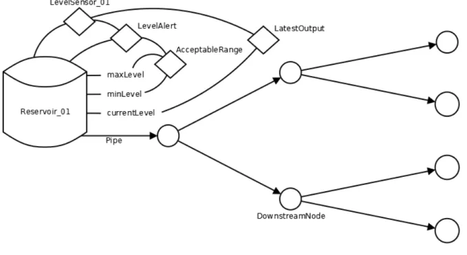
The required inference capability for this use case is illustrated in Figure 7 below, where the green arrows indicate
explicit knowledge, and red arrows represent inferred knowledge.
Figure 7: Problem detection and alert propagation inference use case requirements
Towards achieving the inference ability described, 28 SWRL rules were written, which were utilized by the
in-ference engine alongside the OWL axioms present in the domain ontology. An SWRL rule follows the standard ‘if
THIS then THAT’ approach of rule based logic, where the ‘THIS’ and ‘THAT’ portions consist of SWRL atoms.
An SWRL atom is a statement of truth, such that ‘if THIS (statement is true) then THAT (statement is also true)’.
A full description of SWRL is available from W3C (SWRL: A Semantic Web Rule Language Combining OWL and
RuleML, n.d.). SWRL built-ins include functions for comparisons, maths, and string manipulation etc. This section
now describes the rules produced for each use case, and presents them in SWRL syntax.
5.3.1. deployedAtEntity
As sensors were not explicitly described in terms of the node which they were deployed at, inferring their
sensors. This capability was provided by rule 1.
(1)
S ensor(?S)∧atAsset(?S,?A)∧T opologicalNetworkEntity(?E)
∧atAsset(?E,?A)⇒deployedAtEntity(?S,?E)
5.3.2. observes
Whilst it may be explicitly stated in the knowledge base that a sensor observes a certain property, the SSN ontology
also offers an alternative modelling pattern, such that a sensor is deemed to have a ‘measurement capability’, which is then itself related to the observed property. Where this was the case, it was useful to infer the direct link between
the sensor and the property, to facilitate the previous rules. This was accomplished through rule 2.
(2)
hasMeasurementCapability(?S,?MC)∧f orProperty(?MC,?P)⇒observes(?S,?P)
5.3.3. isActive
This property determines whether an alert is active; relating an alert to a Boolean literal. Inferring this shows the
key benefits of the knowledge based approach utilized: as the sensor descriptions, asset descriptions, alert descriptions,
and dynamic data were all semantically related, it was possible to directly infer whether or not a sensor reading should
trigger an alert. If an alert had an acceptable range, and it was related to a specific sensor, and that sensor’s latest
reading fell outside of the acceptable range, the alarm was triggered. This could occur if the reading was greater
than the allowable maximum, or smaller than the allowable minimum, as otherwise the alarm is not active. This was
formalised through rules 3, 4, and 5.
(3)
WaterAlert(?A)∧hasAlertCondition(?A,?AC1)∧hasAcceptableRange(?AC1,?AR)
∧hasMaxValue(?AR,?Xmax)∧S ensor(?S)∧triggersAlert(?S,?A)
∧hasLatestOut put(?S,?T V P)∧hasValue(?T V P,?X)∧swrlb:greaterT han(?X,?Xmax)
⇒isActive(?A,true)
(4)
WaterAlert(?A)∧hasAlertCondition(?A,?AC1)∧hasAcceptableRange(?AC1,?AR)
∧hasMinValue(?AR,?Xmin)∧S ensor(?S)∧triggersAlert(?S,?A)
∧hasLatestOut put(?S,?T V P)∧hasValue(?T V P,?X)∧swrlb:lessT han(?X,?Xmin)
⇒isActive(?A,true)
(5)
WaterAlert(?A)∧hasAlertCondition(?A,?AC1)∧hasAcceptableRange(?AC1,?AR)
∧hasMinValue(?AR,?Xmin)∧hasMaxValue(?AR,?Xmax)∧S ensor(?S)∧triggersAlert(?S,?A)
∧hasLatestOut put(?S,?T V P)∧hasValue(?T V P,?X)∧swrlb:lessT hanOrEqual(?X,?Xmax)∧swrlb
:greaterT hanOrEqual(?X,?Xmin)
5.3.4. hasDownstreamEntity
In order to generalise pipes, pumps, and reservoirs etc. and determine what is upstream or downstream of an
entity, it was useful to use the IPID values held in the legacy GIS database to infer knowledge about flow chronology
through the entities. This allowed later inference of whether an entity was affected by any given problem, and greatly simplified those rules. Rules 6 and 7 therefore evaluated this for each entity.
(6)
goesFromI pid(?p,?i)∧hasI pid(?u,?i)⇒hasU pstreamEntity(?p,?u)∧hasDownstreamEntity(?u,?p) (7)
goesT oI pid(?p,?i)∧hasI pid(?d,?i)⇒hasU pstreamEntity(?d,?p)∧hasDownstreamEntity(?p,?d)
5.3.5. hasProblem
In the situation that an alert was active, and the alert was caused by a certain problem, it was beneficial to relate
the problem entity to the problem directly, which rule 8 achieved.
(8)
hasAlert(?E,?A)∧ f orProblem(?A,?P)∧isActive(?A,true)⇒hasProblem(?E,?P)
5.3.6. hasAffectedEntity
Tracing the impact of a problem downstream in a water network to determine further problems which the problem
could cause, and its negative consequences for customers, was both highly beneficial and challenging, due to the
system complexity. Further, if a problem was reported at a downstream entity, one expert task is tracing backwards in
the value chain to determine if an upstream problem could be causing it. Rule 9 aimed to empower water experts by
telling them if an entity is affected by any upstream problems. Further, the knowledge of an entity being affected by an upstream problem could be used automatically by a further rule to infer a likely problem at that entity, and even
a required action to proactively mitigate the overall impact of the initial problem. Note that ‘hasProblemEntity’ is a
sub-property of ‘hasAffectedEntity’, which allowed this inference to propagate to all downstream elements.
(9)
WaterAlert(?A)∧isActive(?A,true)∧hasA f f ectedEntity(?A,?E)∧hasDownstreamEntity(?E,?D)
⇒hasA f f ectedEntity(?A,?D)
5.3.7. affectedByProblem
Rule 10 continued the benefits of rule 9 by directly linking the downstream entity with the problem which it was
affected by. Note that ‘hasProblem’ is a sub-property of ‘affectedByProblem’, allowing the inference to propagate to all downstream entities.
(10)
hasDownstreamEntity(?E,?D)∧a f f ectedByProblem(?E,?P)⇒a f f ectedByProblem(?D,?P)
5.3.8. hasSeverity
This inference ability explored the possibility of evaluating how severe a problem was, based on how far outside
the acceptable range a latest sensor reading was. This was achieved in a simple manner by finding the relative absolute
cases, and more domain knowledge about the criteria for problem severity, such as the likely total future impact on the organization’s KPIs. However, the work showed that the knowledge-based approach allowed further knowledge to
be derived quite easily about the current situation, to empower decision makers without them having to do their own
analysis of the data. Firstly, in the case of the reading being greater than the maximum allowable value, severity was
defined by 11.
if ValActual>Valmax: Severity =
ValActual−ValMax
Val
Max−−ValMin
2
(11)
If a problem caused an alert, and the alert was based on an acceptable range, and the alert was triggered by a sensor
whose latest reading was above that range, the severity of the problem was calculated as per equation 11, which was
implemented in SWRL as rule 12
(12)
Problem(?P)∧isCauseO f Alert(?P,?A)∧WaterAlert(?A)∧hasAlertCondition(?A,?AC1)
∧hasAcceptableRange(?AC1,?AR)∧hasMinValue(?AR,?Xmin)∧hasMaxValue(?AR,?Xmax)
∧S ensor(?S)∧triggersAlert(?S,?A)∧hasLatestOut put(?S,?T V P)
∧hasValue(?T V P,?X)∧swrlb:greaterT han(?X,?Xmax)∧swrlb
: subtract(?x1,?Xmax,?Xmin)∧swrlb
:divide(?x2,?x1,2)∧swrlb
: subtract(?S evAbs,?X,?Xmax)∧swrlb
:divide(?S evRel,?S evAbs,?x2)
⇒hasS everity(?P,?S evRel)
In parallel to the above rule, the opposite logic held when the sensor reading was below the minimum acceptable
range, where the severity was calculated as per equation 13 below, and implemented as rule 14
if ValActual<Valmin: Severity =
ValMin−ValActual
Val
Max−−ValMin
2
(13)
(14)
Problem(?P)∧isCauseO f Alert(?P,?A)∧WaterAlert(?A)∧hasAlertCondition(?A,?AC1)
∧hasAcceptableRange(?AC1,?AR)∧hasMinValue(?AR,?Xmin)
∧hasMaxValue(?AR,?Xmax)∧S ensor(?S)∧triggersAlert(?S,?A)
∧hasLatestOut put(?S,?T V P)∧hasValue(?T V P,?X)∧swrlb:lessT han(?X,?Xmin)∧swrlb
:subtract(?x1,?Xmax,?Xmin)∧swrlb
:divide(?x2,?x1,2)∧swrlb
:subtract(?S evAbs,?Xmin,?X)∧swrlb
:divide(?S evRel,?S evAbs,?x2)
⇒hasS everity(?P,?S evRel)
5.3.9. hasDetectionTime
Given that the knowledge base was iteratively updated as new sensor readings are received, and alerts may not be
viewed immediately, it was deemed beneficial to inform decision makers exactly when a problem was first observed.