1. Features
l
Interface with Wii Nunchuk remote control directly. Modification the remote control is not
required.
l
Two-wire Interface. Easy to interface with any modern microcontroller
l
Connect to INEX microcontroller board via 3-pin JST connector.
l
+5Vdc supply voltage. On-board +3.3V regulator.
l
2x4 cm. size.
2. Board contents :
l
ZX-NUNCHUK board
x 1
l
JST3AA-8 cable
x 2
l
Documentation
x 1
The Wii-Nunchuk remote control is optional. This is also sold separated. Controller is provided in
the Nunchuk Interface kit (#8000347).
3. General information
There is 3-axis accellerometer sensor
LIS3L02AL
of ST Microelectronics inside the
Wii-Nunchuk. It includes a 10-bit A/D converter, an analog joystick and 2-button switches. The figure
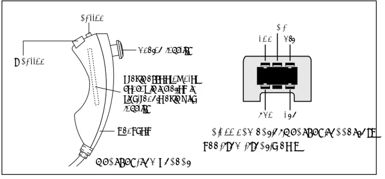
1 shows the components of Wii-Nunchuk and connectorís pin assignment.
Pin assignment of Nunchuk connector.
See from front view.
+3.3V SDA N/C SCL GND
C button
Analog joystick
Z button
Handheld
3-axis acceleromoter
sensor is installed in
right-angle axis with
joystick
Figure 1 : Wii-Nunchuk remote control information
Nunchuk component
+3.3V K1 SCL IC1 78L33 K2 SDA +3.3V GND SCL SDA IN GND OUT C1 0.1PF 16V C2 0.1PF 16V C3 47PF 16V R3 47 R4 47 GNDSCL +5V. GNDSDA +5V. R1 4.7k 4.7kR2
¡Ã³Õ㪡ѺÃкº 3.3V. ã˶ʹ IC1 78L33 ÍÍ¡
áÅǵÍä¿ IN ä»Âѧ OUT à¾×èÍ㪧ҹ (¢Ò 3 ¡Ñº ¢Ò 1 ¢Í§ IC)
¤Í¹à¹ç¡àµÍÃ
Nunchuk
ZX-NUNCHUK
µÍä»ÂѧºÍô
POP-INTERFACE ËÃ×Í JX-POP
Figure 2 : ZX-NUNCHUK scematic diagram and shows the connecting with Wii-Nunchuk
The wiring signal of Wii-Nunchuck has 4 lines. It includes +3.3V supply voltage (red line),
Ground (white line), Serial clock line - SCL (yellow line) and Serail data line - SDA (green line).
They are connected to special female connector and assigned pin location are shown in the
figure 1.
The interfacing protocol is 2-wire interface or I
2C bus compatible. The logic level is +3.3V.
The ZX-NUNCHUK is designed for bridging between any modern microcontroller and Wii-Nunchuk
remote control. The 3-axis accellerometer sensor can detect accelleration ± 2g maximum. The
schematic diagram of ZX-NUNCHUK and how to interface with the Wii-Nunchuk remote control
are shown in figure 2.
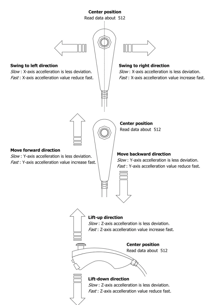
Figure 3 : Wii-Nunchuk physical operation
Center position Read data about 512
Swing to left direction
Slow : X-axis accelleration is less deviation.
Fast : X-axis accelleration value reduce fast.
Swing to right direction
Slow : X-axis accelleration is less deviation.
Fast : X-axis accelleration value increase fast.
Center position Read data about 512
Move backward direction
Slow : Y-axis accelleration is less deviation.
Fast : Y-axis accelleration value reduce fast. Move forward direction
Slow : Y-axis accelleration is less deviation.
Fast : Y-axis accelleration value increase fast.
Lift-up direction
Slow : Z-axis accelleration is less deviation.
Fast : Z-axis accelleration value increase fast.
Lift-down direction
Slow : Z-axis accelleration is less deviation.
Fast : Z-axis accelleration value reduce fast. Center position Read data about 512
4. Protocol
Wii-Nunchuck is a slave I
2C bus device. It has 2 slave ID for writing (0xA4) and reading
(0xA5) data which is as follows :
0 1 0 0 1 0 R/W
1
The reading data of the Wii-Nunchuk consists of 6 bytes data. Before using these data,
programmer must decode these data following :
Exact data
= (Redaing data
XOR
0x17) + 0x17
The summary of exact data after decoding can show as follows :
0x00 0x01 0x02 0x03 0x04 0x05 Joystick X Joystick Y
Accelerometer X (bit 9 to bit 2 for 10-bit resolution) Accelerometer Y (bit 9 to bit 2 for 10-bit resolution) Accelerometer Z (bit 9 to bit 2 for 10-bit resolution) Accel. Z
bit 1 Accel. Zbit 0 Accel. Ybit 1 Accel. Ybit 0 Accel. Xbit 1 Accel. Xbit 0 C-button Z-button
Address Data byte receive
Byte 0x00 :
X-axis data of the joystick
Byte 0x01 :
Y-axis data of the joystick
Byte 0x02 :
X-axis data of the accellerometer sensor
Byte 0x03 :
Y-axis data of the accellerometer sensor
Byte 0x04 :
Z-axis data of the accellerometer sensor
Byte 0x05 :
bit 0 as Z button status - 0 = pressed and 1 = release
bit 1 as C button status - 0 = pressed and 1 = release
bit 2 and 3 as 2 lower bit of X-axis data of the accellerometer sensor
bit 4 and 5 as 2 lower bit of Y-axis data of the accellerometer sensor
bit 6 and 7 as 2 lower bit of Z-axis data of the accellerometer sensor
5. Programming
5.1 Initialize start Nunchuk command
Set the Nunchuk as ready after power-on. Write the command 0x40 and 0x00 follows
the slave ID byte 0xA4. Normally this command is written at once.
0xA4 0x40
START Device STOP
Ack. DeviceAck.
0x00 Device Ack.
5.2 Conversion command (0x00)
Send this command to get all sensor data and store into the 6-byte register within Nunchuk
controller. This must be execute before reading data from the Nunchuk.
0xA4 0x00
START Device STOP
Ack. DeviceAck.
5.3 Data read command
Send the slave ID for reading (0xA5) and wait for the stream data 6-byte from the Nunchuk.
0xA5 Byte2
START
STOP Byte3
Byte4 Byte5 Byte6
Device Ack.
Byte1 Master
Ack. MasterAck. MasterAck.
Master
Ack. MasterAck. Masterno Ack.
Next, decode the data to exact data by XOR with 0x17 and plus with 0x17. This step is
very important. Do not skip this step !
6. Example : Interface Nunchuk with Arduino POP-168
This example show the data reading from Wii-Nunchuk by Arduino POP-168 microcontroller
module. The POP-168 is fit on the POP-Interface baord or Project board (JX-POP168). Connect
with Wii-Nunchuk via ZX-NUNCHUK interface board. The reading data will be shown on the Arduino
IDEís Serial monitor. The construction circuit is shown below. The example C code shows in the
Listing 1.
1 12 13 ATMEGA1 68 POP-168 Di 1/TxD Di 0/RxD ! GND " # $ % An 3/PC3 & ' An 6/AN6 An 7/AN7 GND VDD/+5Vdc Di 9/PWM/PB1 Di 8/PB0 Di 7/PD7 Di 6/PWM/PD6 Di 5/PWM/PD5 Di 4/PD4 # Di 3/PWM/PD3 Di 2/PD2 " ! " ! ' & % $ RESET 2 3 5 SW2 RESET +5V K1 RS-232 IC1 POP-168 DB-9 (optional) An 2/PC2 An 1/PC1 An 0/PC0 An 5/SCL/PC5 An 4/SDA/PC4 RM1 Nunchuk ZX-N U N CHUK SDA SCL M µÍ¨Ò¡¨Ø´µÍ¢Í§ºÍô POP-INTERFACE /******************************************************************************** * Code for read data from Wii nunchuck., base on http://www.windmeadow.com/node/42 * File : ArduinoNunchuk.pde* by : K.Worapoht
* Hardware: Arduino, POP-168 , AVR ATMega168 , * connect SDA to PC4 (An4) and SCL PC5 (An5)
*******************************************************************************/ #include <Wire.h>
#define nunchuk_ID 0xA4 >> 1
unsigned char buffer[6];// array to store arduino output int cnt = 0;
void setup () {
Serial.begin (9600);
Wire.begin (); // join i2c bus with address 0x52
nunchuck_init (); // send the initilization handshake delay (100);
}
void nunchuck_init () {
Wire.beginTransmission (nunchuk_ID); // transmit to device 0x52
Wire.send (0x40); // sends memory address
Wire.send (0x00); // sends sent a zero.
Wire.endTransmission (); // stop transmitting
}
void send_zero () {
Wire.beginTransmission (nunchuk_ID); // transmit to device 0x52
Wire.send (0x00); // sends one byte
Wire.endTransmission (); // stop transmitting
}
void loop () {
Wire.requestFrom (nunchuk_ID, 6); // request data from nunchuck while (Wire.available ())
{
buffer[cnt] = nunchuk_decode_byte (Wire.receive ()); // receive byte as an integer
cnt++; }
// If we recieved the 6 bytes, then go print them if (cnt >= 5)
{
print (); }
cnt = 0;
send_zero (); // send the request for next bytes delay (100);
}
// Print the input data we have recieved // accel data is 10 bits long
// so we read 8 bits, then we have to add // on the last 2 bits.
void print () {
unsigned char joy_x_axis; unsigned char joy_y_axis; int accel_x_axis;
int accel_y_axis; int accel_z_axis;
unsigned char z_button; unsigned char c_button; joy_x_axis = buffer[0]; joy_y_axis = buffer[1];
accel_x_axis = (buffer[2]) << 2; accel_y_axis = (buffer[3]) << 2; accel_z_axis = (buffer[4]) << 2;
// byte outbuf[5] contains bits for z and c buttons
// it also contains the least significant bits for the accelerometer data // so we have to check each bit of byte outbuf[5]
if ((buffer[5] & 0x01)!=0) { z_button = 1; }
else
{ z_button = 0; }
if ((buffer[5] & 0x02)!=0)
MNT-ZXNUNCHUK20080717
else{ c_button = 0; }
accel_x_axis += ((buffer[5]) >> 2) & 0x03; accel_y_axis += ((buffer[5]) >> 4) & 0x03; accel_z_axis += ((buffer[5]) >> 6) & 0x03; Serial.print (joy_x_axis, DEC);
Serial.print ("\t");
Serial.print (joy_y_axis, DEC); Serial.print ("\t");
Serial.print (accel_x_axis, DEC); Serial.print ("\t");
Serial.print (accel_y_axis, DEC); Serial.print ("\t");
Serial.print (accel_z_axis, DEC); Serial.print ("\t");
Serial.print (z_button, DEC); Serial.print ("\t");
Serial.print (c_button, DEC); Serial.print ("\r\n");
}
// Encode data to format that most wiimote drivers except // only needed if you use one of the regular wiimote drivers char nunchuk_decode_byte (char x)
{
x = (x ^ 0x17) + 0x17; return x;
}
Listing 1 : Arduino C code for interfaing Wii-Nunchuk with Arduino POP-168 (final)
Figure 4 : Shows the reading data from Wii-Ninchuk remote control on the Arduinos
serial monitor. First 2 bytes are X and Y axis data of Joystick. Next 3 bytes are X,
Y and Z axis of accellerometer sensor and last 2 bytes are C and Z button status.
If any button is pressed, the data will equal 0.