Bio-Plex
Manager
TMSoftware 4.1
User Guide
Bio-Rad Laboratories, Inc. Life Science Group2000 Alfred Nobel Drive Hercules, CA 94547
Bio-Rad Technical Support Department
The Bio-Rad Technical Support Department in the United States is open Monday– Friday, 6:00 a.m. to 5:00 p.m., Pacific Standard Time. Worldwide technical support is available on the Web at http://www.consult.bio-rad.com/.
Phone: (800) 424-6723, option 2, option 3 (510) 741-6910, option 2, option 3 Fax: (510) 741-5802
E-mail: [email protected] (U.S.) [email protected] (International) Web: http://www.consult.bio-rad.com/
Notice:
No part of this publication may be reproduced or transmitted in any form or by any means, electronic or mechanical, including photocopy, recording, or any information storage or retrieval system, without permission in writing from Bio-Rad.
Bio-Rad reserves the right to modify its products and services at any time. This user guide is subject to change without notice.
Although prepared to ensure accuracy, Bio-Rad assumes no liability for errors or omissions, or for any damages resulting from the application or use of this information.
The following are trademarks of Bio-Rad Laboratories: Bio-Rad, Bio-Plex, and Bio-Plex Manager. All other trademarks, including Windows, Cheminert, Tween, Pentium, Dell, and Titertube are registered trademarks of their respective companies. No rights or licenses under any of Luminex Corporation’s patents are granted by or shall be implied from the sale or acquisition of this Bio-Plex system containing Luminex technology (the “System”) to you, the end-user. By using this System, you agree that (i) the System is sold only for use with fluorescently labeled microsphere beads authorized by Luminex (“Beads”), and (ii) you obtain rights under Luminex’s patents to use this System by registering this System with Bio-Rad in accordance with the instructions accompanying this System and purchasing a kit containing Beads.
Table of Contents
1.
Bio-Plex Suspension Array System
Overview... 1
Components ... 2
Advantages... 3
For More Information…... 4
Bio-Rad Technical Support ... 4
2.
Bio-Plex Manager Software Overview ... 5
Software Editions... 5
Software Licenses ... 5
Note on this User Guide ... 6
Compatibility with Luminex® IS 2.3 Software ... 6
General Workflow ... 7
Types of Files ... 8
Key Software Features ... 8
3.
Software Installation... 9
System Requirements ... 9
Required Screen Resolution... 9
Installing the Software ... 10
4.
Getting Started ...13
Starting Bio-Plex Manager ... 13
Communication to the Array Reader and Microplate Platform ... 13
Connecting to the Array Reader and Platform ...14
Disconnecting and Reconnecting...15
Menu and Toolbars ... 15
Status Bar ... 15
Quick Guide ... 16
Sample Needle Adjustment... 17
5.
System Controls ...21
Bio-Plex MCV Plate III... 21
Start Up ... 23
Optics Warm Up and Shut Down ... 24
Calibration ... 25
Opening the Calibration Dialog Box ...26
Calibration Microsphere Control Numbers ...27
Calibration Set Up ...29
Performing the Calibration...30
Calibration Log ...31
Wash Between Plates ... 33
Remove Air Bubbles ... 33
Unclog ... 34
Validation Log ... 40
Platform Heater ... 42
Instrument Information ... 44
Eject/Retract Plate ... 44
Additional Instrument Functions ... 45
Cancel Operation... 46
Shut Down ... 46
Instrument Operations Log ... 47
6.
Preparing a Protocol ... 49
Protocol Files ... 49
Creating/Opening Protocol Files ... 49
Saving Protocols... 50
Protocol Window... 51
Step 1. Describe Protocol ... 53
Step 2. Select Analytes ... 53
Selecting Analytes ... 54
Customizing Analytes and Panels ... 55
Combining Panels of Analytes... 59
Step 3. Format Plate ... 59
Plate Formatting... 61
Plate Groupings ... 68
Printing the Plate Format ... 71
Step 4. Enter Standards Info ... 71
Selecting External Standards ... 73
Step 5. Enter Controls Info ... 82
Step 6. Enter Sample Info (optional) ... 85
7.
Running the Protocol
...87
Run Protocol Window... 87
Bead Count ... 89
Sample Timeout ... 89
Advanced Settings ... 90
Bead Map Selection ...90
Sample Size ...91
Save Options...91
Sampling Errors...92
DD Gates...93
PMT Voltage...94
Plate Loading Guidelines ... 95
Running the Protocol... 95
Manually Stopping a Reading ... 97
Generating Results from a Protocol ... 97
Histogram and Bead Map ... 98
Histogram ...100
Bead Map ...104
Raw Data Table ... 108
Bead Statistics...109
Sampling Error Codes ...110
Raw Data Display Options ...111
Other Table Formatting ...113
8.
Analyzing the Results ... 115
Results Files ... 115
Opening a Results File ... 115
Saving a Results File ... 116
Results Window ... 117
Viewing/Changing the Protocol Settings... 118
Changing the DD Gate Range... 120
Raw Data ... 121
Setting the Plate ID ... 122
Exporting the Raw Data ... 122
Printing the Raw Data ... 123
Report Table ... 123
Report Table Columns ... 124
Report Table Options... 126
Replicate Groups ... 128
Selecting Outliers... 129
Obs/Exp*100 Column ... 130
Conc in Range Column... 131
Table Formatting... 131
Copying the Report Table ... 132
Exporting the Report Table... 132
Printing the Report Table ... 136
Standard Curve ... 136
Regression Methods ... 138
Linear versus Logistic Regression Methods ... 141
Copying the Standard Curve ... 142
Printing the Standard Curve ... 142
9.
Bio-Plex Manager Security Edition...147
Overview ... 147
Users, Passwords, and User Levels ... 149
Enabling and Disabling Secure Mode ... 150
User Authentication... 151
Electronic Records ... 152
File Security and Validation...152
Calibration, Validation, and Instrument Operations Logs...153
Secure Protocol and Results Files ...153
Audit Trail ...159
Protected Directories...163
Locking Bio-Plex Manager Security Edition ... 163
Logging Off... 163
Appendix ...165
Troubleshooting Guide ... 165
Glossary ... 171
Table Error Codes ... 179
Security Edition: User Access by Function ... 181
Basic Concepts ... 187
Microsphere Handling ... 189
Reporting Problems ... 193
Software Warranty ... 195
1. Bio-Plex Suspension
Array System Overview
The Bio-Plex suspension array system is a flow-based dual-laser system for simultaneously identifying and quantitating up to 100 different analytes in a single biomolecular assay (xMAP technology) . The system detects and measures molecules bound to the surfaces of fluorescent microspheres, providing highly accurate, real-time digital analysis of serum or culture media samples as small as 50 µl. This allows for quantitative analysis of a wide variety of cell biology assays, including immunoassays, complex genetic assays, and enzymatic assays.The Bio-Plex suspension array system is fully integrated, and consists of an array reader and microplate platform, validation and calibration reagents, a selection of cytokine and phosphoprotein assays, sample preparation reagents, and a computer running Bio-Plex Manager software.
The assays contain sets of microscopic color-coded beads, each of which is conjugated with a different reactant.
Reactants can include:
• DNA
• Enzyme substrates
• Receptors
• Antigens
• Antibodies
These can be used to create, for example, a capture sandwich immunoassay.
To perform a multiplex reading, samples are mixed with conjugated microsphere and reactant mixtures and fluorescent reporter molecules are added. The assays are loaded into the wells of a 96-well microtiter plate and the plate is inserted into the microplate platform. The platform and array reader are controlled by a computer running Bio-Plex Manager software.
The detection system in the array reader uses two lasers to analyze the microspheres in a flow stream. The first laser identifies each microsphere and its associated analyte based on the fluorescent signature of the microsphere, and the second measures the amount of analyte using the reporter molecules attached to the analytes. When the reading is complete, Bio-Plex Manager displays the raw data and generates detailed summary reports.
Components
A certified Bio-Rad service engineer will install the complete Bio-Plex suspension array system at your site, including the array reader, platform, and computer. The system setup procedure is described in the Bio-Plex Suspension Array System Hardware Instruction Manual.
The Bio-Plex suspension array system includes the following components:
• Bio-Plex MCV Plate III (required for use with Bio-Plex Manager 4.0 and later)
• A Pentium®-class PC, preinstalled with operating system, Microsoft® Excel,
Microsoft® Internet Explorer, Microsoft.net, and Bio-Plex Manager
Workstation software
• Software package, containing Bio-Plex Manager CD-ROM, user guide, and a hardware protection key
• Instrument manual for array reader and microplate platform
• Sample tube holders (two sizes, large and small)
• Sheath fluid bottle
• Sample needles (two long)
• Protective shield
• Needle adjustment tool
• Waste bottle
• Communications cable to connect the reader to the computer
• Communications cable to connect the microplate platform to the computer
• Computer monitor
• Power cords
• Computer keyboard
• Computer mouse
• HTF (High Throughput Fluidics), if selected
The Bio-Plex suspension array system comes with these reagents:
• Bio-Plex Calibration Kit (CAL1 and CAL2)
• Bio-Plex Validation Kit 4.0 (optics, fluidics, reporter, and classify components)
• Sheath fluid
Advantages
With the Bio-Plex suspension array system, you can:
• Simultaneously quantitate up to 100 different analytes from culture media and serum samples as small as 50 µl.
• Automatically analyze all the samples in a 96-well microtiter plate— yielding up to 9,600 data points—in about 30 minutes.
• Instantly customize your experiments by mixing Bio-Plex assays or creating your own assays.
• Analyze results, prepare reports, and print and/or export data immediately after each reading.
• Provide a complete electronic audit trail of data generation and analysis in a secure digital environment with multilevel account access, compliant with the Code of Federal Regulations, title 21, Part 11, “Electronic Records; Electronic Signatures.”
For More Information…
For more information on the principles and concepts of the Bio-Plex suspension array system, see Basic Concepts on page 187, or visit our Web site at
http://www.bio-rad.com/bio-plex.
Bio-Rad Technical Support
Bio-Rad Technical Support in the United States is open Monday–Friday, 6:00 a.m. to 5:00 p.m., Pacific Standard Time. Worldwide technical support is available on the Web at http://www.consult.bio-rad.com/.
Phone: (800) 424-6723, option 2, option 3 (510) 741-6910, option 2, option 3 Fax: (510) 741-5802
E-mail: [email protected] (U.S.) [email protected] (International) Web: http://www.consult.bio-rad.com/
2. Bio-Plex Manager
Software Overview
Bio-Plex Manager software runs on a computer installed with the Windows® 2000 or
XP operating system, and requires a hardware protection key, also known as a HASP key, installed on either the computer itself or the computer network system (see page 12). The software features a standard Windows® interface, with pulldown
menus, toolbars, and keyboard shortcuts.
Bio-Plex Manager comes in two editions—Standard Edition and Security Edition— and with three available licenses: Workstation, Desktop, and Network. These editions and licenses are described below. The computer included with the Bio-Plex suspension array system comes preinstalled with a compatible operating system and Bio-Plex Manager Standard Edition, Workstation license.
Software Editions
Bio-Plex Manager software comes in two editions:
• Standard Edition gives all users equal access to all features of the software
with no restrictions and no electronic audit trail.
• Security Edition provides different levels of users access to different
features of the software and creates a complete electronic audit trail of all data generation and analysis. Security Edition can be run in Secure Mode, with all the security features enabled, or Standard Mode, which behaves like the Standard Edition of the software. Note that Bio-Plex Manager Security Edition must be installed on the Windows® 2000 or XP Professional
operating system for full security functionality. For more details, see Chapter 9.
Software Licenses
• Workstation license enables the software to control the array reader and
microplate platform and collect, analyze, and output data.
• Desktop license enables the software to analyze data files but not control
the array reader and platform. The instrument communication and control functions described in Chapters 4, 5, and 7 are not available with this license.
• Network license provides Desktop licenses to multiple users over a
computer network. Like the Desktop license, it enables the software to analyze data files but not control the array reader and platform.
Note on this User Guide
The main body of this user guide assumes that you are using the Standard Edition of the software with a Workstation license, unless otherwise noted. The Security Edition of the software and its user levels and restrictions are described in detail in Chapter 9.
Compatibility with Luminex
®
IS 2.3
Software
If you install Bio-Plex Manager 4.0 or later on a computer with Luminex® IS 2.3
software or later, note the following:
To avoid communication conflicts with the array reader and platform, do not run Bio-Plex Manager and Luminex IS 2.3 at the same time.
If you switch between the two software applications, you must re-calibrate the array reader before acquiring data.
Consult your Luminex documentation for instructions on using Luminex IS 2.3 software.
General Workflow
To collect, analyze, and output data using Bio-Plex Manager, you follow the general steps outlined below:
1. Start up and calibrate the array reader.
2. Open or create a protocol file, and specify the analytes that you want to detect, the layout of the 96-well plate, and information about your standards.
3. Run the selected protocol. 4. Review the results.
5. Print and/or export the data.
Select analytes, standards, and plate format
Run the Protocol
Generate reports and review results
Print and export the data Start up and calibrate array reader
Figure 2. Workflow for Bio-Plex Manager
The Quick Guide, which displays automatically at startup, is designed to guide you
through the typical Bio-Plex Manager workflow, from start up and calibration through shut down. Commands such as Start Up and Calibrate open dialog boxes
Types of Files
There are two main types of files created and used by Bio-Plex Manager:
• Protocol files (see page 49) contain the settings and controls for reading a
microplate.
• Results files (see page 115) contain the data from each reading and tools
and reports for analyzing that data.
The application database file (bioplexdata.mdb) is installed on your hard drive or
file server when you install the software. This database contains calibration, validation, and instrument operations information. See page 11 for more details.
Key Software Features
The key features of Bio-Plex Manager software include:
• Graphical user interface
• Complete control of the array reader and microplate platform
• Automated maintenance, calibration and validation functions
• Automatic error detection and logging system
• Bead map and histogram
• Raw data reports
• Data reduction
• Logistic curve-fitting algorithms
• Calculation of unknown concentrations and ratios
• Export to Microsoft® Excel, text files, and XML format
• Microplate platform heater control
• Complete electronic audit trail of data generation and analysis (Security Edition)
• Different levels of user access (Security Edition)
3. Software Installation
The Bio-Plex Manager CD can be used as described in the following section to install, reinstall, or upgrade Bio-Plex Manager software.System Requirements
Component Minimum Recommended
Operating system Windows® 2000 or XP Windows® 2000 or XP
Professional Processor Pentium III or equivalent,
933 MHz Pentium III or higher, 1 GHz or higher Hard disk space 4 GB 40 GB
System memory 256 MB 512 MB Screen resolution 1024 × 768 1024 × 768 Screen colors 256 colors 24-bit True Color Ports for connecting
instrument (required for Workstation license only)
2 RS232 serial ports 1 RS232 serial port and 1 USB port
Port for connecting HPK 1 USB port 1 USB port Other software Internet Explorer 6.0 or
later Microsoft Excel 2000 or later Internet Explorer 6.0 or later Microsoft Excel 2000 or later
Required Screen Resolution
Your computer screen resolution must be set to at least 1024 × 768 pixels for correct display of the Bio-Plex Manager interface. The status bar and some dialog boxes will not display properly at lower resolution. If your display is currently set to a lower resolution:
1. Go to the Windows Start menu, select Settings, and select Control Panel.
3. In the Display Properties dialog, select the Settings tab.
4. Drag the Screen Area slider to the right (More) until you have selected 1024 by 768 pixels. Click on OK to accept the settings.
Figure 3. Changing the screen settings.
Installing the Software
To install, reinstall, or upgrade the software, insert the Bio-Plex Manager CD into the CD-ROM drive on your computer.
Before reinstalling Bio-Plex Manager, we recommend that you first uninstall any
existing version of Bio-Plex Manager on your computer.
We recommend that you turn off any anti-virus protection software before
installation. Such software, if active, can greatly slow the progress of the installation. If you are unable to turn off your anti-virus protection software, allow 15 minutes for complete installation. Do not cancel the installation during this period.
Microsoft.net
Microsoft.net is automatically installed on your computer when you install Bio-Plex
Manager. It is required to support the logistic curve fitting features of Bio-Plex Manager.
Bioplexdata.mdb File
During installation, you will be prompted to save the application database file (bioplexdata.mdb) to a location on your hard drive or a file server. This database
file contains logs of calibration, validation, and instrument operations activity for your instrument.
• For more information about the Calibration Log, see page 31.
• For more information about the Validation Log, see page 40.
• For more information about the Instrument Operations Log, see page 47. You can save the bioplexdata.mdb file to any folder on your computer; the default location is the Bio-Plex Manager application folder. If your computer is connected to multiple instruments, each instrument must have a separate bioplexdata.mdb file saved in a different folder.
For more information about the calibration, validation, and instrument operations logs in Bio-Plex Manager 4.1, Security Edition, see page 153.
Note that the bioplexdata.mdb file is not compatible with versions of Bio-Plex Manager earlier than 4.0. If you have an earlier version of the software, installing version 4.0 or later will copy the data from your existing database file (bioplex.mdb) into the new database. A copy of your old database will remain in the application folder.
Luminex LXR Directory and Files
A directory called Luminex is automatically created in the Program Files folder on
your computer during installation. Inside this folder is a folder called LXR that
contains various applications for monitoring and communicating with the array reader and platform. A Windows® service called LXService is also installed and
started. This service enables automatic communication with the instrument when you open Bio-Plex Manager.
Hardware Protection Key (HASP Key)
A hardware protection key, also known as a HASP key, is required to run Bio-Plex Manager. The HASP key determines the license (Workstation, Desktop, or Network) and the edition (Standard or Security) of Bio-Plex Manager.
Workstation or Desktop HASP keys must be attached to a USB port on the computer running the software. Network HASP keys must be attached to a USB port on the network file server computer.
The HASP key has a driver that is automatically installed when you install Bio-Plex Manager.
Uninstalling
To uninstall Bio-Plex Manager from your computer, use the Windows Add/Remove Programs function. Click on the Windows Start button, select Settings, select Control Panel, double-click on Add/Remove Programs, and follow the instructions
4. Getting Started
Before starting Bio-Plex Manager, make sure the Hardware Protection Key (see page 11) is attached to your computer, and switch on the array reader and the microplate platform. This turns on the optics inside the array reader and enables communication between the array reader and software.
Avoid using other applications while Bio-Plex Manager is communicating with the array reader. Running other applications may interrupt communication between Bio-Plex Manager and the array reader.
Starting Bio-Plex Manager
To start Bio-Plex Manager, click on the application icon on your desktop or select
Bio-Plex Manager 4.1 from the Programs directory on your Windows Start menu.
Figure 4. Bio-Plex Manager 4.1 desktop icon.
The software will open and connect to the array reader and platform.
Communication to the Array Reader
and Microplate Platform
The computer running Bio-Plex Manager software is connected to the array reader by a serial or USB cable, and to the microplate platform by a serial cable. See the
Bio-Plex Suspension Array System Hardware Instruction Manual or the manual sent with the Luminex 100 IS 2.3 systemfor a description of the cable connections.
Connecting to the Array Reader and Platform
Communication between the computer and the array reader and microplate platform is automatically established when you open Bio-Plex Manager. If Bio-Plex Manager is unable to communicate with the instrument, a dialog box will prompt you to check the connections.
Figure 5. Connection Error dialog.
Make sure the instrument is turned on and check the cable connections, then click on
Reconnect in the dialog. If you are still unable to connect, try restarting the
computer, array reader, and platform. If you experience further difficulties, contact Bio-Rad technical support (see page 4).
If you do not want to automatically connect to the array reader and platform when you open the software, select the Do not connect at startup checkbox. This is useful
if you are not connected to an instrument or want to use the software without connecting to the instrument. To re-enable automatic connection at startup, select
Disconnecting and Reconnecting
Communication between the computer and the array reader and platform is closed when you exit Bio-Plex Manager. If you need to disconnect from the array reader and platform without shutting down Bio-Plex Manager software (e.g., to
troubleshoot the instrument), go the Instrument menu and select Disconnect.
To reconnect to the array reader and platform while Bio-Plex Manager is running, select Reconnect from the Instrument menu. This will also enable automatic
connection each time you start the software, if it has been disabled (see previous section).
See the Bio-Plex system hardware manual or the Luminex 100 IS 2.3 system manual for specific instructions.
Menu and Toolbars
Bio-Plex Manager includes a menu bar and main toolbar at the top of the application window.
The pulldown menus contain all the major functions of the software. Note that these menus change depending on whether you are displaying a Protocol window, a Results window, or neither.
The main toolbar includes the major instrument controls, including Start Up, Shut Down, Wash, Unclog, etc. The various Protocol and Results windows also contain
their own toolbars, with commands specific to those windows. These are described in greater detail in the following chapters.
Status Bar
The instrument status bar shows the current state of the instrument (Calibration,
Warm Up, Ready, Pressurizing, etc.). It includes a Cancel button for canceling the
Figure 6. Instrument status bar.
When the array reader is performing an operation, the time remaining for the operation will be shown in the instrument status bar.
The Bio-Plex Manager software status bar is below the instrument status bar, and provides information about the command under the cursor. This information is continuously updated as you move your cursor over the software window.
The software status bar also shows the current user and, if you are using the Security Edition of the software, whether you are in Secure Mode (shown as a “locked” symbol ) or Standard Mode (shown as “unlocked” ). See Chapter 9 for more information about Bio-Plex Manager Security Edition.
The software status bar also shows the Caps Lock, Scroll Lock, and Num Lock keyboard status.
Quick Guide
When Bio-Plex Manager first opens, a Quick Guide toolbar is displayed in the upper
right corner of the screen. The Quick Guide is designed to guide you through the
typical workflow when using the system, from start up and calibration through shut down.
Figure 7. Bio-Plex Quick Guide.
By default, the Quick Guide opens automatically when you start Bio-Plex Manager.
To disable this feature, deselect the Show at Startup checkbox at the bottom of the
guide.
To open the Quick Guide after it has been closed, select Quick Guide from the View
menu.
Sample Needle Adjustment
See the Bio-Plex Hardware Manual or the Luminex manual for instructions on installing the sample needle.
The height of the array reader sample needle must be adjusted when (1) the style of microtiter plate has changed or (2) when the sample needle is replaced. The sample needle height is the same for flat bottom or filter plates. Note that, for round bottom plates, the needle must be raised so that it is slightly above the bottom of the round bottom well.
If you adjust the sample needle for use with round bottom plates, you will not be able to use the MCV Plate III without readjusting the needle to filter-plate height.
With the array reader and platform switched on, go to the Instrument menu, go to the Set Up submenu, and select Adjust Needle. The Adjust Needle dialog box will open.
Figure 8. Adjust Needle dialog.
Then follow the steps below:
1. Click on the Eject/Retract button to eject the plate holder, and place the MCV
Plate III on the microplate platform with the arrow pointing toward the array reader.
2. While holding the platform door open, click on the Eject/Retract button again
to retract the plate.
3. Tape the access door of the microplate platform open. You must be able to see inside the access door.
Warning: DO NOT stick your hands and fingers inside the platform
at any time.
4. Click on the Up/Down button in the Adjust Needle dialog to lower the needle
into the needle adjustment well in the MCV Plate III.
5. Using the hex key needle adjustment tool (supplied with the array platform), loosen the screw at the top of the needle so that the needle housing can move up and down freely.
6. Move the knurled dial on the needle arm and manually move it downward so that it just touches the bottom of the needle adjustment well. Use a flashlight to
7. Tighten the needle set screw so that it is no longer possible to manually move the needle.
8. Click on the Up/Down button in the dialog a couple of times to make sure that
the needle moves freely up and down. The needle should not push down on the MCV Plate III.
9. Finally, remove the tape so that the platform door can open and close normally, and click on the Close button to close the Adjust Needle dialog.
5. System Controls
This chapter covers the Bio-Plex Manager commands that control basic system functions, such as instrument start up, warm up, calibration, validation, and shut down.
The Start Up, Warm Up, and Calibration functions must be performed prior to running an assay with Bio-Plex Manager, and all together take about 45 minutes.
When performing the following operations, the sheath fluid container and the waste fluid container should be closely monitored.
The sheath fluid bottle must be placed at the same level as the array reader, unless you are using the Bio-Plex High-Throughput Fluidics (HTF; see caution below) or Luminex Sheath Delivery System (SDS). The fluid level should be below the air inlet connection and above the sheath outlet connection. Always check the sheath fluid level before starting a run or procedure.
If you are using the Bio-Plex HTF or Luminex SDS, it should sit on the counter next to the array reader, while the sheath fluid cube should be placed ~3–4 feet below the array reader (e.g., on the
floor).
The waste fluid container receives waste from the system. Do not allow the waste container to overflow! Empty the waste bottle
each time the sheath fluid bottle is filled. The waste container should be placed on the bench next to the instrument. Never place this container on top of the instrument. All waste containers should have vented caps.
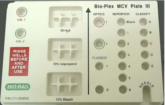
Bio-Plex MCV Plate III
Bio-Plex Manager 4.0 and later require the use of the Bio-Plex MCV Plate III (MCV stands for maintenance, calibration and validation). This plate contains wells marked
for the different types of fluids used in validation, washing, calibration, and other functions. The Bio-Plex MCV Plate III has been modified from the previous MCV plate to work with Bio-Plex Validation Kit 4.0, with its enhanced Reporter and Classify bead sets. It also includes an open needle well for ease of needle adjustment. Bio-Plex Manager 4.0 and later require the use of the Bio-Plex MCV Plate III, the Bio-Plex Validation Kit 4.0, and the Bio-Plex Calibration Kit.
Figure 9. Bio-Plex MCV Plate III.
When a particular procedure (e.g., Calibration) requires you to add solutions to the Bio-Plex MCV Plate III, the dialog box describing the procedure will include a diagram of the MCV Plate III with the wells to be loaded highlighted in blinking yellow.
Wells highlighted in yellow
Figure 10. Highlighted wells in diagram indicate wells to be filled.
Start Up
Start up is a series of fluidics functions that prepares the array reader to acquire data. This process requires the Bio-Plex MCV Plate III, distilled water, and 70 percent isopropanol. Start up takes approximately 10 minutes.
You do not need to wait for the array reader optics to warm up before performing the start up procedure.
Click on the Start Up button on the Quick Guide or main toolbar or select the
command from the Instrument menu. Follow the step-by-step directions in the dialog
Figure 11. Start Up dialog.
Insert the prepared plate into the microplate platform and click on OK to begin the
start up process.
Optics Warm Up and Shut Down
To ensure accurate and reproducible results, the optics (i.e., the lasers) in the array reader must warm up for at least 30 minutes prior to calibration, validation, and reading assays. Optics warm up begins when you first turn on the array reader. You can proceed with the array reader start up procedure described in the previous section while the optics are still warming up. However, if you try to perform calibration, validation, or an assay reading, you will receive a warning message. You can cancel the warm up procedure using the Cancel Operation command on
the Instrument menu or the Cancel button in the status bar; however, this is not
recommended. Results for identical readings may vary if the optics have not reached optimal operating temperature.
If you attempt to start a reading during warm up, you can eject the plate carrier using the Eject/Retract Plate command on the main toolbar and remove the plate for
To begin warm up after automatic power down, click on the Warm Up button
on the main toolbar or select the command from the Instrument menu.
If you attempt to perform a reading after automatic power down, you will receive a warning message and the optics will begin warming up.
Calibration
Calibration of the array reader is essential for optimal performance and day-to-day reproducibility of results. Calibration is required:
• Each day after the start up procedure is complete and the optics have warmed up.
• If the array reader temperature changes by more than 2º C during the course of the day (if the temperature changes by more than 2º C, a message box will prompt you to recalibrate).
• Before data acquisition if you switch between Bio-Plex Manager and Luminex IS 2.3 software installed on the same computer (see page 6). Before calibrating, make sure that optics warm up is complete.
The Bio-Plex Calibration Kit contains calibration microspheres (CAL1 and CAL2 beads) with stable fluorescent intensities in the RP1, CL1, and CL2 wavelength ranges. The calibration process uses these microspheres to adjust voltage settings for optimal and consistent microsphere classification and reporter readings over time and across different instruments. Current calibrated settings are automatically applied to any new session.
Calibration using Bio-Plex Manager requires the Bio-Plex MCV Plate III, the CAL1 beads and CAL2 beads from the Bio-Plex Calibration Kit, and DI water. The CAL1 beads calibrate the array reader’s doublet discriminator and classification channels, while the CAL2 beads calibrate the array reader’s reporter channel for reporter fluorescence detection.
Opening the Calibration Dialog Box
To begin calibration, click on the Calibrate button on the Quick Guide or main
toolbar, or select Calibrate from the Instrument menu. The Calibrate dialog box will
open.
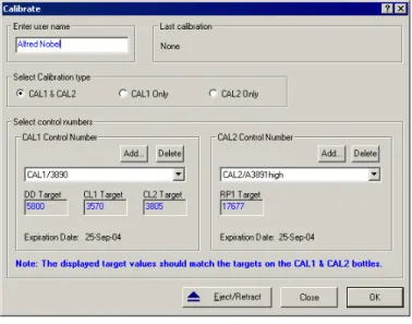
Figure 12. Calibrate dialog.
At the top of the dialog box, enter your name in the field. If you are using the Security Edition of the software in Secure Mode, your user name will be listed and grayed out.
The time and date of the last calibration using Bio-Plex Manager are listed, as is the temperature at the time of that calibration. If the temperature has not changed by more than 2º C in a single day, it is not necessary to recalibrate the instrument. Next, select the calibration type by clicking on the CAL1 & CAL2, CAL1 only, or CAL2 only button. You should perform both CAL1 and CAL2 calibration daily.
Calibration Microsphere Control Numbers
Under Select Control Numbers, you can either select existing control numbers for
your CAL1 and CAL2 microspheres or enter new control numbers.
Select existing control numbers from the pulldown list, and the target values for the control numbers will appear in the appropriate fields.
When you receive a new Bio-Plex Calibration Kit, you must add the new CAL1 and CAL2 control numbers and target values to the Calibrate dialog. These numbers are
printed on the bottles containing the beads.
It is critical that you enter the correct target values for your CAL1 and CAL2 calibrators. Entering incorrect values will result in an incorrectly calibrated array reader, which will adversely impact assay results.
To add a new CAL1 control number, click on the Add button under CAL1 control number in the Calibrate dialog. The Add New CAL1 Control Number dialog box will
open.
Figure 13. Adding a new CAL1 control number.
In the dialog, enter the control number from the CAL1 bottle in the Enter Control Number field. If the expiration date is printed on the bottle, select the option button
next to the date field under Expiration Date and click on the pulldown button next
Figure 14. Calendar selection box
Scroll through the calendar using the scroll buttons at the top. Select a particular date by clicking on it.
Next, enter the DD, CL1, and CL2 target values for the control number, as printed on the bottle, in the appropriate fields.
If you are using a Luminex-type assay from another manufacturer, do not use the DD target value specified in the manufacturer's manual. Use only the DD target value on the Bio-Plex CAL1 bottle.
When you are done, click on Add to close the dialog box and save your changes.
To add a new CAL2 control number, click on the Add button under CAL2 control number in the Calibrate dialog box. The Add New CAL2 Control Number dialog box
Figure 15. Adding a new CAL2 control number.
In the dialog, enter the control number from the CAL2 bottle in the field. Select the expiration date, if printed on the bottle, as described above. Next, enter the High RP1 or Low RP1 target value for the control number, as printed on the bottle, in the RP1
field.
The CAL2 calibration bottle label lists two different RP1 target values: Low RP1 and High RP1. Bio-Plex phosphoprotein assays require calibration using the High RP1 target value, while Bio-Plex cytokine assays may be calibrated with either the Low or High RP1 target value. Other Luminex-type assays typically require calibration with the Low RP1 target value. Check with your assay supplier.
When you are done, click on Add to close the dialog box and save your changes.
Your new control numbers will be added to the selection lists in the main Calibrate
dialog.
To delete a particular control number, first select it in the Calibrate dialog box, then
click on the Delete button.
Calibration Set Up
When you have specified your control numbers of calibration microspheres and specified the type of calibration you want to perform (CAL1 & CAL2, CAL1 only, or CAL2 only), click on OK in the Calibrate dialog.
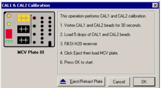
Another dialog box will list step-by-step instructions for preparing the Bio-Plex MCV Plate III.
Figure 16. Preparing the Bio-Plex MCV Plate III for CAL1 & CAL2 calibration.
When preparing the MCV Plate III, note the following:
• Important: Before vortexing, remove the calibration beads from 2–8°C
(36–46°F) storage and allow to warm to room temperature. Vortex each bottle for 30 seconds. Proper resuspension of the microspheres is essential for efficient calibration.
• Never dilute the calibration beads, and be careful to limit their exposure to light. Store at 2–8° C immediately following calibration.
• Load 5 drops of beads (approximately 200 µl) per reservoir (CAL1 or CAL2).
• The DI H2O well of the MCV Plate III holds about 3 ml of distilled water.
Performing the Calibration
Click on the Eject/Retract Plate button to eject the microplate platform plate
carrier, place the MCV Plate III in the carrier with the arrow facing toward the platform, then retract the plate. Click on OK to start the calibration process.
As calibration proceeds, the status bar at the bottom of the Bio-Plex Manager window will monitor the progress of calibration. The number of beads per second
Number of beads per second should be 100 or higher
Figure 17. Status bar during calibration.
Because calibration beads are highly concentrated, calibration is followed by three wash cycles using distilled water.
An alert box will notify you whether calibration has succeeded or failed. If the calibration process failed, check the MCV Plate III to verify that the correct beads were added to the wells. Then perform a fluidics Wash (page 45) and repeat the
above steps. For more information, consult the Troubleshooting guide on page 165.
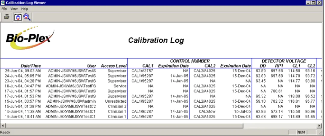
Calibration Log
The Calibration Log provides a list of past calibration dates and times, results, instrument settings, and other data obtained by Bio-Plex Manager. This data is stored in a log file called bioplexdata.mdb, which by default is saved in the main Bio-Plex
Manager application folder on your computer.
Note that this database is not compatible with versions of Bio-Plex Manager earlier than 4.0. If you have an earlier version of Bio-Plex Manager, installing version 4.0 or later will copy the data from your existing database (bioplex.mdb) into the new database. A copy of your old database will remain in the application folder. To open the Calibration Log, go to the View menu and select Calibration Log. The
Figure 18. Calibration Log viewer.
Each calibration is listed by date and time. If you are using Bio-Plex Manager Security Edition in Secure Mode, the User and Access Level columns list
information about the user who was logged into the application when each calibration was performed. The Result column notes the result of each calibration,
including whether it passed or failed.
If you see a drastic change in a detector’s voltage from one calibration to the next, it could indicate a problem with the instrument. A steadily increasing detector voltage may indicate that the laser is decreasing in intensity.
On the toolbar, click on Calibration Detail to display additional information for
each calibration, including detector gain. Click on Calibration Log to return to
the default view.
For CAL1-only calibrations, the RP1 column will display a entry of NA (not applicable). For CAL2-only calibrations, the DD, CL1, and CL2 columns will display entries of NA.
To print the calibration report, select Print from the File menu. Print Preview
Wash Between Plates
You should wash the fluidics lines between each plate reading to prevent traces of sample or other debris from building up inside the system. Click on the Wash Between Plates button on the Quick Guide or main toolbar, or select the
command from the Instrument menu. A dialog box will guide you through the steps
for preparing the MCV Plate III for a wash procedure.
Figure 19. Steps for washing between plate readings.
Add 70% isopropanol and distilled water to the appropriate reservoirs, insert the plate in the microplate platform, and click on OK. This procedure performs a series
of different fluidics operations and will take several minutes. After initial system pressurization (5–20 seconds), the time remaining in the operation will be displayed in the Bio-Plex Manager status bar.
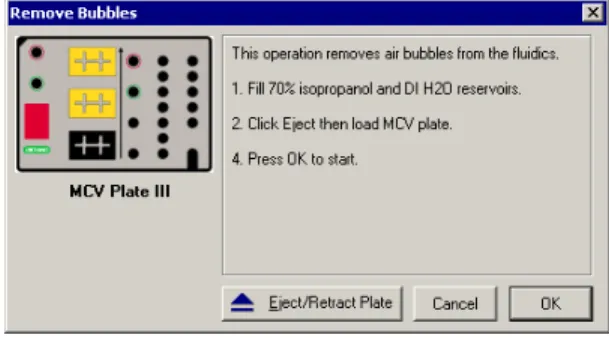
Remove Air Bubbles
Microscopic air bubbles in the cuvette may cause a sudden shift in the bead regions during an assay reading. If the array reader detects such a shift, the reading will stop and you will be prompted to perform an alcohol wash to force air bubbles out of the system.
Click on the Remove Bubbles button on the main toolbar or select the
command from the Instrument menu. A dialog box will guide you through the steps
Figure 20. Steps for removing air bubbles from the fluidics system.
Add 70% isopropanol and distilled water to the appropriate reservoirs, insert the plate in the microplate platform, and click on OK. This procedure performs a series
of different fluidics operations and will take several minutes. After initial system pressurization (5–20 seconds), the time remaining in the operation will be displayed in the Bio-Plex Manager status bar.
Unclog
If the array reader detects an unusually low bead count during a reading, you will be prompted to perform an Unclog operation to remove possible obstructions from the
fluidics lines. Click on the Unclog button on the main toolbar or select the
command from the Instrument menu. An instruction box will guide you through
Add 10% bleach solution and distilled water to the appropriate reservoirs, add 5 drops of CAL1 beads to the CAL1 reservoir, insert the plate in the microplate platform, and click on OK. This procedure performs a series of fluidics operations
and reads a sample of CAL1 beads to verify that the fluidics are operating properly. It will take several minutes. After initial system pressurization (5–20 seconds), the time remaining in the operation will be displayed in the Bio-Plex Manager status bar.
Validation
Validation of the array reader is a formal process for documenting that the
instrument is fit for its intended use and that it is kept in a state of maintenance and calibration.
Validation is performed after Start Up and Calibration have been performed.
Validation is dependent on successful calibration for accuracy. You should perform a validation reading:
• Once a month
• Each time you move the array reader, or
• To diagnose any problems with the array reader that cannot be solved by other procedures (calibrating, washing, unclogging, etc.).
Validation Kit
Bio-Plex Manager requires the use of Bio-Plex Validation Kit 4.0 to perform validation. It must be used in conjunction with the Bio-Plex MCV Plate III. Each Bio-Plex Validation Kit consists of reagents and procedures to evaluate:
• Optical alignment
• Reporter channel performance
• Efficiency of multiplexing
• Integrity of fluidics
The Bio-Plex Validation Kit validates the operation of all of the primary components of the array system, and can also be used to discriminate between assay and
Validation Kit Control Number
Each Bio-Plex Validation Kit has a control number linked to the specifications for the kit. You must use the mini-CD included in the kit to install the control number on your computer. After installation, you can select the control number in Bio-Plex Manager as described in the following section.
See the Bio-Plex Validation Kit manual for more information.
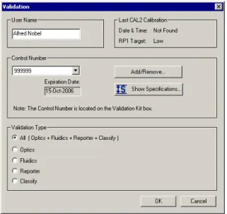
Setting Up a Validation Run
To set up a validation reading, click on the Validation button on the main
toolbar or select the command from the Instrument menu. The Validate dialog box
will open.
Figure 22. Validate dialog.
Control Number Selection
Select the Control Number for your specific Bio-Plex Validation Kit from the
Control Number pulldown list. The expiration date for the control number will be
listed below the field.
If the control number is not available in the list, or the list is too long and you want to limit it to the control numbers you are using, click on the Add/Remove button.
Figure 23. Add/Remove Control Numbers dialog.
The Add/Remove Control Numbers dialog lists all the available validation Control
Numbers. To make Control Numbers available in the Validate dialog pulldown list,
you must add them to the Selected List. To select all the numbers in the Available List, click on the Add All>> button. To add control numbers individually,
double-click on them, or select multiple numbers using Shift + double-click and Ctrl + double-click key combinations and click on the Add>> button. Use the <<Remove and <<Remove All buttons to unselect them. At least one Control Number must remain in the Selected List.
When you click on OK, the Control Numbers in the Selected List will be added to
the pulldown list in the Validate dialog.
To view the specifications for a Control Number, select the number from the pulldown list and click on the Show Specifications button. The Control Number Specifications dialog box will list the validation specifications.
Figure 24. Control Number Specifications dialog.
Validation Type Selection
In the Validate dialog, select the type of validation you want to perform using the
Validation Type option buttons: All, Optics, Fluidics, Reporter, or Classify.
Performing a Validation Run
When you have made your selections in the Validate dialog, click on OK. The dialog
See the Bio-Plex Validation Kit manual for information about the bottles in the Validation Kit, and instructions on loading the Bio-Plex MCV Plate III for
validation. When you have prepared the plate according to the instructions, click on
Eject/Retract Plate in the dialog box, place the plate on the plate carrier, and click
on OK.
Validation Results
After a run, the Validation Results dialog box will automatically open. You can also
view this dialog by going to the View menu and selecting Validation Results.
Figure 26. Validation Results dialog.
The Validation Results dialog box includes tabs for each type of validation. If you
selected and performed All Validations, all the tabs will be available. Otherwise, only the tab for the validation you performed (Optics, Fluidics, Reporter, or Classify) will be available and displayed.
Click on Create Report to generate and display a Microsoft® Excel spreadsheet
showing the validation results. Note that Microsoft® Excel 2000 or higher must be
installed on your computer for this function to work (Excel comes preinstalled on all computers supplied with the Bio-Plex suspension array system).
See the Bio-Plex Validation Kit 4.0 manual for interpreting the results of a validation run.
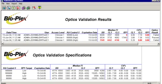
Validation Log
Each validation run is recorded in the Validation Log. This log is stored in a secure database file called bioplexdata.mdb, which by default is saved in the main
Bio-Plex Manager application folder on your computer.
Note that this database is not compatible with versions of Bio-Plex Manager earlier than 4.0. If you have an earlier version of Bio-Plex Manager, installing version 4.0 or later will copy the data from your existing database (bioplex.mdb) into the new database. A copy of your old database will remain in the application folder. To view this log, go to the View menu and select Validation Log.
Access Level columns list information about the user who was logged into the
application when each validation was performed.
Use the buttons in the upper left corner of the window to view the different validation types (Optics , Fluidics , Reporter , and Classify ).
To print the Results window, click on the Print Report Results button . To print
the Specifications window, click on the Print Specifications button .
To show or hide the specifications data in the Validation Log viewer, click on the
Show/Hide Specifications Window button .
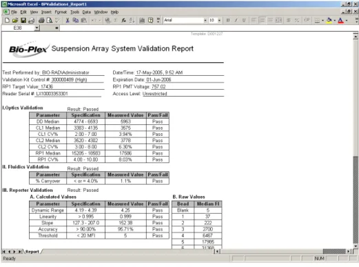
To create a spreadsheet report for a particular validation run, click on the row for the run in the Results window. It will appear selected, as will the specifications
associated with the Control Number for that run in the lower window. Then click on
Create Report . A Microsoft® Excel spreadsheet will be automatically generated
and displayed showing all the validation data for that run. Note that Microsoft®
Figure 28. Validation Results spreadsheet (Microsoft® Excel).
Platform Heater
The microplate platform has a heater for warming samples. The heater has an operating range of 35ºC to 60ºC (95ºF to 140ºF), and can be controlled through Bio-Plex Manager.
To access the heater controls, select Platform Heater from the Instrument menu, or
Figure 29. Platform Heater dialog.
In the Platform Heater dialog, click on the Turn Heater on checkbox to turn on the
heater, and set the target temperature within the range 35–60ºC using the scroll buttons.
To automatically turn the heater off at the end of a run, select the Turn Heater off after run checkbox.
The dialog box and the Bio-Plex Manager status bar will indicate the current platform temperature. The status bar will also indicate whether the heater is turned on.
Figure 30. Status bar with heater on.
If the heater is in the process of warming up or cooling down, the temperature will be shown in red. If the heater is on and has reached the specified temperature, the temperature will be shown in green. If the heater is off and is at ambient temperature, the temperature will be displayed in black.
If you initiate a run before the heater has warmed up or cooled down (i.e., the temperature is shown in red), you will have the option of waiting until the specified temperature is reached or proceeding with the run immediately.
Instrument Information
The array reader continuously monitors its internal temperature, voltage, pressure, and other systems for diagnostic purposes. You can access this information by clicking on the Information button on the main toolbar or selecting Information from the Instrument menu.
Figure 31. Instrument Information dialog.
Click on the tabs in the dialog to access different information about the instrument. See the hardware manual for detailed instrument specifications.
Eject/Retract Plate
The Eject/Retract Plate command on the main toolbar and Instrument menu
ejects and retracts the plate carrier in the microplate platform. Note that every function that requires insertion of a plate into the platform (e.g., Start Up, Wash, Calibrate, etc.) includes an Eject/Retract button in its dialog box.
Additional Instrument Functions
The Additional Functions submenu under the Instrument menu contains secondary
instrument fluidics functions. Selecting one of these commands will open a dialog box to guide you through the procedure. Many of these functions require the use of the Bio-Plex MCV Plate III.
Major fluidics functions such as Wash Between Plates, Remove Bubbles, Unclog,
etc. consist of combinations of the following functions.
Wash
The Wash command performs a single fluidics system wash using DI water. It can
be used to remove traces of sample in the fluidics pathway. Note that this procedure is less comprehensive than Wash Between Plates (page 33)
Select Wash from the Additional Functions submenu of the Instrument menu and
follow the steps in the dialog box.
Drain
This command completely drains the fluidics system of the array reader—for example, if you need to move the instrument. Make sure you have enough room in your waste fluid container to prevent overflow.
Prime
This command primes the fluidics system with sheath fluid.
Sanitize
This command performs a comprehensive cleansing of the fluidics system using 10 percent bleach and DI water.
Alcohol Wash
Alcohol Flush
This command performs a comprehensive cleaning of the fluidics system using 70 percent isopropanol.
Back flush
This command flushes sheath fluid through the fluidics system in the opposite direction of sample flow, to remove particle obstructions from the cuvette.
Cancel Operation
The Cancel button, located in the status bar at the bottom of the Bio-Plex Manager
window, can be used to cancel many of the instrument functions, including
calibration, validation, or any of the fluidics functions. Click on the Cancel button to
cancel the current operation. An alert box will prompt you to confirm the cancellation.
Figure 32. Cancel button in the status bar.
Shut Down
The shut down procedure consists of a series of functions designed to clean the fluidics lines and prevent a build up of debris within the system. To initiate this process, select Shut Down from the main toolbar or Instrument menu, and
Figure 33. Shut Down dialog.
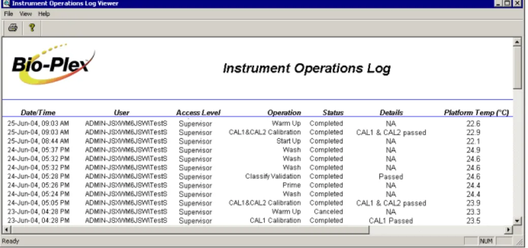
Instrument Operations Log
Each instrument operation you perform with Bio-Plex Manager is recorded in the Instrument Operations Log. This log is stored in a secure database file called
bioplexdata.mdb, which by default is saved in the main Bio-Plex Manager
application folder on your computer.
Note that this database is not compatible with versions of Bio-Plex Manager earlier than 4.0. If you have an earlier version of Bio-Plex Manager, installing version 4.0 or later will copy the data from your existing database (bioplex.mdb) into the new database. A copy of your old database will remain in the application folder.
To view this log, go to the View menu and select Instrument Operations Log. The
Figure 34. Instrument Operations Log
Each instrument operation is listed by date and time. If you are using Bio-Plex Manager Security Edition in Secure Mode, the User and Access Level columns list
information about the user who was logged into the application when each operation was performed.
To print the log, click on the Print button .
To copy the information in the log to the Windows® clipboard and paste it into
another document, drag your cursor over the rows and columns in the table to select them, and use the Ctrl + C key command to copy the data.
6. Preparing a Protocol
Protocol Files
A Protocol file contains the parameters of a Bio-Plex Manager reading. It specifies
the analytes used in the reading, the plate wells to be read, sample information, the values of standards and controls, and instrument settings.
Protocol files also contain the controls for performing the reading. When the reading is complete, the settings in the Protocol file are copied into the Results file, along with the data from the reading.
You can save Protocol files and reuse or modify them for other readings. Raw data from the most recent reading is stored in the Protocol file, and you can generate a new Results file from this data.
Creating/Opening Protocol Files
To create a new Protocol file, click on the New button on the main toolbar or
Quick Guide or select New from the File menu. A new Protocol window will open.
To open an existing Protocol file, click on the Open button on the Quick Guide
or main toolbar or select Open from the File menu. Locate and select the file using
the standard Windows®
Open dialog.
Standard Protocol files have the file extension *.pbx. Secure Protocol files, created
using Bio-Plex Manager Security Edition, have the file extension *.spbx. For more
information about Secure Protocol files, see page 153.
Secure Protocol files can only be opened as read-only files using the standard
Protocol files created or modified by Bio-Plex Manager 4.0 or later cannot be opened by earlier versions of the software.
You can generate a new Protocol file from the settings stored in a Results file (see the next chapter for information about Results files). With the Results file open, select New Protocol from Results from the File menu. A new Protocol window will
open.
Saving Protocols
To save the settings in a Protocol, click on the Save button on the main toolbar or
select Save from the File menu.
After you have performed a reading (see Running the Protocol on page 87), the
data from that reading is also saved with the Protocol file. This data is overwritten in the Protocol file whenever you rerun the Protocol. To preserve the data from multiple readings, you must save separate Results files (see page 115).
Use Save As on the File menu to save a Protocol under a different name. You can
create a new Protocol by opening an existing Protocol, modifying the settings, selecting Save As, and specifying a new name for the modified Protocol.
Reducing the File Size of Protocols
Protocol files that include all the data from a reading can be very large
(>5 megabytes). Much of this file size is due to the raw bead event data from the reading, which is used to generate the bead map and histogram displays. If you require a smaller file size (e.g., you want to send the Protocol file via email), you can save a copy of the file without this raw bead event data, but with the other numerical
data from the reading intact.
We strongly recommend keeping a copy of the original Protocol file with the raw bead event data intact. This data is necessary for changing the DD gate range in the Results file (see page 120), and can also be exported in XML file format from the Results file (see page 143) for further analysis.
In the Save As dialog box, select the Compressed mode checkbox to save the
Protocol file without the bead map and histogram data. All other data will be preserved.
Select this checkbox to reduce the file size of a Protocol containing reading data
Figure 35. Save As dialog for Protocols.
Note that this compressed file option is not available for Secure Protocol files generated using the Security Edition of the software (see page 153).
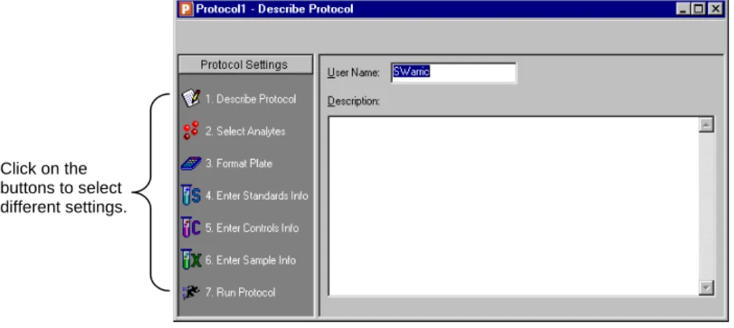
Protocol Window
The Protocol window is divided into a series of subwindows, each containing different controls and settings. Navigate through the different subwindows using the buttons along the left side of the Protocol window.
Click on the buttons to select different settings.
Figure 36. Protocol window.
The buttons are numbered to guide you through the selection process: 1. Describe Protocol (optional) (see page 53).
2. Select Analytes (see page 53). 3. Format Plate (see page 59). 4. Enter Standards Info (see page 71). 5. Enter Controls Info (see page 82). 6. Enter Samples Info (see page 84). 7. Run Protocol (see page 87).
Step 1. Describe Protocol
The Protocol description window is displayed when you first open a Protocol. (Otherwise, click on the Describe Protocol button to display this window.) Entering
a description of your Protocol is optional.
If you are using the Standard Edition of the software, the Author field contains your
computer login name. If you are using the Security Edition, the field contains your user name. Enter a new name in the field, if desired, and enter a description of the assay reading in the Description field.
Step 2. Select Analytes
In this step, you select the analytes that you want to detect in the reading.
During a reading, the array reader will always detect all the analytes in the sample,
including any that you have not selected. However, analytes that were detected but not selected will by default not appear in the final reports and tables. After a reading, you can go back and correct your selections in the Protocol window and/or the Results file, and the detected analytes will appear in the tables.
Figure 37. Select Analytes window.
Bio-Plex Manager groups analytes by panels. Preconfigured panels of analytes are built into the software; these panels correspond to off-the-shelf Bio-Plex assays, and include human, mouse, and rat cytokines and phosphoproteins. You can add to these existing panels of analytes, or create new panels that contain only the analytes that you use in your experiments.
First you select the panel of analytes that you want to detect, and then you select the specific analytes.
Selecting Analytes
Go to the Panel pulldown menu and select from the list of preconfigured panels. The
analytes in the selected panel will be displayed in the Available list.
Each analyte is listed by name and region number. The region number refers to the
region of a fluorescent color map used to identify the analyte’s bead set. Each bead set is embedded with specific quantities of two fluorescent dyes; the combination of these fluorochromes, as detected by the array reader, places the bead set within a unique region on the color map, thereby identifying the set and its associated analyte. To move an individual analyte into the Selected list, double-click on it. Double-click
Hold down the Shift or Ctrl key and click on multiple analytes in the Available list to
select them as a group. Then click on the Add >> button to move them over to the
Selected list. Use the <<Remove button to return multiple selected analytes back to
the Available list.
Use Add All>> to move all the available analytes into the Selected list, and
<<Remove All to move them back.
3. Use the buttons to move your selections to the Selected column. 2. Select the
analytes in the Available
column.
1. Select the panel of analytes.
Figure 38. Selecting the analytes to be detected.
Some analytes share the same region. Only one analyte per region can be added to the Selected list.
Customizing Analytes and Panels
Bio-Plex Manager comes preconfigured with a selection of panels and analytes that Bio-Rad provides as Bio-Plex assays. You can edit these and/or create new ones. If you have assay kits for analytes that are not included in Bio-Plex Manager, you will need to add these analytes using the commands described in this section.
Creating a New Panel of Analytes
Click on the Add Panel button in the toolbar to create a new panel of analytes.
Figure 39. Creating a new panel of analytes.
Enter a name for the panel in the top field, then click on Add to add analytes to the
panel. The Add Analyte dialog box will open.
Figure 40. Adding a new analyte.
Enter the bead region number of the first analyte in the Region field, and the analyte
name in the Name field.
The bead region number must be correct for proper detection of analytes. Confirm that this number is correct before proceeding.
After you have added several analytes to the panel you are creating, you can use the
Sort buttons at the bottom of the Add Panel dialog to sort them. Click on an analyte
in the list to select it, then click on the appropriate arrow to move it up or down in the list.
Sort buttons
Figure 41. Sorting analytes.
You can also remove an analyte from the list by selecting it then clicking on the
Remove button, or