An Energy Aware Key Establishment Framework for
Wireless Sensor Network Security
D.C.Jullie Josephine
*, Dr.T.Jebarajan
**, Dr.R.S.Rajesh
****
Joe Suresh Engineering College
**
Principal, Kings Engineering College, Chennai.
***
Reader/CSE,M.S.University
Abstract- Wireless sensor networks are networks consisting of nodes with sensors to monitor physical or environmental conditions. Resource constraint nature of wireless sensor network (WSN) turns the security issue certainly into a big challenge. Security is critical for sensor network due to the limited resource constraints nature of sensor nodes. Security can be provided in various ways such as in key generation, distribution, storage etc. In our work we present a secure framework against various attacks in WSN by three key management schemes and how the attacks are identified and protected by these three schemes. The proposed scheme has low memory consumption, computation time and energy to run in a node.. Also we propose a new energy efficient clustering algorithm which clusters the nodes in an energy efficient way and the data‟s are distributed by Multipath broadcast protocol. Further, we prove that the proposed secure framework against various attack and performance is analyses with certain metrics. The work is organized as Section I-Introduction, Section II-Network Entities, Section III-Architecture, Section IV Clustering and Head selection, Section V-Proposed methods, Section VI- Evaluation metrics, Section VII-Performance analysis ,section VIII-Conclusion.
Index Terms- Base station (BS), Cluster Head (CH), Key distribution center (KDC),Node Allocation Table(NAT) and Wireless Sensor Network (WSN)
I. INTRODUCTION
raditional methods using a filing a cabinet or manual administration were implemented to protect the information from outsiders. But nowadays all the documents are in electronic form. With the introduction of the computer, the need for automated tools for protecting files and other information stored on the computer became evident. Most initial computer application had no security. This continued for a number of years until the importance of data was truly realized. When computer application were developed to handle financial and personal data, the real need for security rise. To protect data to thwart attackers, the collection of tools were designed to provide computer security. The security are needed to protect the data during their transmission is termed as Network Security. Security in sensor network is a work to protect the data as well as the communication links should also be secured. Sensor networks are easier to attack and harder to protect than other types of networks. In many cases, sensor networks are deployed in open, unattended areas that anyone can access. The wireless nature of
communication between the sensor nodes makes it easy to eavesdrop, intercept and inject bogus information into an unprotected network. The security problem becomes even more crucial when we allow wireless sensors not only to gather data about people and the environment, but also to actuate on their own, based on their sensor readings. It is obvious that such a revolution in computing puts security solutions to a great test. Wireless sensor networks are clearly a very challenging environment for applying security services. They differ in many aspects from traditional fixed, networks and standard cryptographic solutions cannot be used in this application space. Looking at existing security mechanisms for WSNs, we can see that they are still in their early stages and the level of security provided is not satisfactory for many applications. Despite many research efforts, the problems of key distribution and authentication are still open and require new cryptographic solutions. These new security frameworks have to take advantage of specific sensor network features and to meet the strict limitations of WSN hardware platforms.
Another key challenge in WSN is to deal with is energy efficiency because most sensor nodes may be battery-powered. In most cases, it may not be possible to change or recharge batteries, either due to the low-cost hardware being used or due to an inaccessible area the nodes are deployed in. To prolong the overall network operational lifetime, the energy consumption of a sensor node should thus be minimized as far as possible. Most of the nodes components will therefore be turned off most of the time and will only be used if they are required. Thus, communication in a WSN is one of the main energy consumers and deserves particular consideration. In order to fulfill these requirements, the protocols and algorithms used should be energy-efficient
A recent technology review indicates that sensor technology is one of the ten emerging technologies that will change the world [1].Wireless Sensor networks which usually consist of a large number of ultra-small autonomous devices. Each device called sensor node, is a battery powered and equipped with integrated sensors, a data processing unit, and a short range radio communication unit, as in Figure: 1.1. Wireless Sensor Networks(WSN) are being widely used in many applications such as sensing and tracking the battle field in military, industry measurement and control, environmental monitoring etc In this network there are generally two kinds of devices: sensor nodes and base station. As soon as nodes are deployed in a field ,
Figure: 1 components of sensor network
the event and transmit sensing data to the base station [1],[2].Resources on sensor network nodes are very low , it causes a hard key management for wireless sensor networks. Since sensor nodes are scattered in rough environment, it is difficult to know where sensor nodes can be easily exposed to an adversary. It makes a sensor node unable to trust any nodes easily. Finally, Wireless sensor networks are considered so large that key management must support node addition without any centralized controller. The most important thing in security is to share the keys among the nodes of wireless sensor networks because an adversary can overhear communication among the nodes and there is no centralized controller responsible for secure communication. Many key schemes have been studied in [9],[10],[11]. When designing a key management scheme for WSN designers should take the following five major resource constraints of sensor nodes into consideration (1) limited energy (2) limited memory (3) limited power (4) limited communication bandwidth (5) limited communication range.
The proposed framework presents an energy efficient key establishment scheme in sensor networks. The existence of key materials allows sensor networks to be able to add new nodes for replacement later. In this method a single Key is used (symmetric) and all computation are done in the cluster head and base station. The base station will create a NAT table which shows all nodes ID and weight of nodes based on the energy used in the nodes which in turn a Cluster Head can be selected. Addition of node is easy which answers scalability. An efficient key management based on Eschenauer and Gligor‟s method is applied to reduce memory requirements and increase the security level. The cell size is optimal to increase network connectivity and reduce the number of transmission hops. Sensor nodes in each cell negotiate among each other so that only one node, called coordinator, stays awake and the others fall into sleeping mode for the sake of energy.
II. NETWORKENTITIES
We assume that the functionality of various nodes in the network
Sensor Nodes: Each sensor node is assigned a unique ID number by the base station and a main key before it is deployed. Sensor nodes communicate with the base station using the key encrypted data. Node ID number is saved in the base station. A base station in the network is allocated with an initial key (Ks) when the sensor nodes are first clustered. The key is erased from memory after the clustering is completed. The sensor node has the key
Cluster Head: A cluster head is a sensor node with better resources and may be used to collect and merge local traffic and
send it to the base station. During the network operation, the cluster head is responsible for the integration of all cluster node data and transmitting the data to the base station. The communication between the cluster head and cluster members uses authentication key Kc for encryption.
Clusters: A cluster is composed of a cluster head and node members. Each cluster has a unique cluster ID number and a cluster key Kc.
Base Stations: A base station is typically a gateway to another network, a powerful data processing/storage center, or an access point for human interface. Base stations collect sensor readings, perform costly operations .On behalf of sensor nodes, it manages the network. In some applications, base stations are assumed to be trusted and tamper-resistant. Thus, they are used as key distribution centers.
The objective is defined in four aspects
1. Defining a good architecture-proposed a Cluster architecture
2. Defining cluster Head selection- proposed a good algorithm in which the Ch is elected and the response time is defined as T=1000ms and energy consumed is calculated. 3. Defining a secure mechanism in key management– by comparing three schemes, a good key establishment scheme is defined.
4. Defining a good protocol –Mutipath broadcast protocol in which the communication overhead and storage overhead is reduced and throughput for this protocol is calculate d.
Henceforth a new secure mechanism is defined in our work.
III. ARCHITECTURE
Two models defined, they are layered architecture and clustered architecture. As in the figure: 2, in layered architecture the nodes are arranged and deployed in layers
(a) Layered architecture
It consists of a single powerful base station (BS).all the sensor nodes are arranged in layers around the base station. The nodes i-hop away from BS.
Figure: 2 Layered Architecture
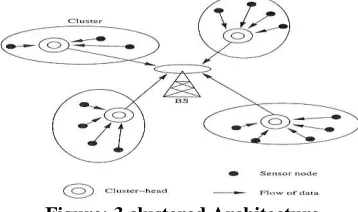
(b) Clustered architecture
The framework includes
Level: 1 The proposed framework works in clustered architecture and the nodes deployed are clustered by neighbor discovery process.
Level: 2 after the nodes are clustered; a NAT table is generated by the base station which used for cluster head selection procedure. The cluster head selection procedure selects the node which has less weight by using the NAT table generated by the base station. Hence the CH is elected after a time interval “T” seconds.
Level: 3 A symmetric key establishment frameworks is designed and compared with two other schemes for its performance.
[image:3.612.76.255.293.399.2]Level: 4 A new protocol is framed, henceforth the framework works in energy efficient way. In this framework no routing table is used and all messages are broadcasted in multiple active path with sequence number and received in the either side.
Figure: 3 clustered Architecture
IV. CLUSTERING&CLUSTERHEADSELECTION
Two major types of cluster-based key management protocols are widely used protocol, introduced byJolly et at.[8] The other is the lightweight key management protocol, proposed by Eltoweissy, et al. [3][4] However, these two protocols suffer the following security issues:
1. Key information is exchanged mainly through the communication between cluster heads. The weakness of this
approach is that once a cluster head is compromised, the entire cluster will be broken by simple DOS attack.
2. All assume fixed cluster heads in a WSN, and require cluster heads to possess big storage capacity and high computing power. The cluster heads will not change during the operation. Being energy efficient, because if the network cannot dynamically select cluster heads to balance energy consumption, the nodes that are far away from the cluster heads will exhaust their energy first and the network will contain "blind spots". The sensor nodes are deployed in the field. with a unique ID and each cluster head is also deployed with a unique ID. In the initial stage the cluster Head has an ID and each CH broadcast a Hello message .The nodes in that radio range will be clustered to that Cluster Head by giving acknowledgement. Thus the cluster is formed. An NAT (Node Allocation Table) structure is created by the Base station. It includes the nodes ID and weight of each node.
4.1 Node Allocation Table (NAT)
Typical protocols include the logic level binary tree (LKH) protocol, introduced by Waller et al. This protocol is simple and flexible in management, and each group member node only needs to keep log2 (N) (N: number of members nodes in the group) keys to update key group, but the group needs to keep 2log2 N−1 keys. When a group has a large number of members,
the required storage space is very big. The NAT group key algorithm is introduced to address this issue. Node allocation table (NAT) provides a framework for scalable and efficient key management. With this new key management scheme,[25] the storage efficiency is nearly doubled compared with LKH. In this protocol the base station will generate a NAT structure. According to the cluster head selection algorithm a node broadcast the Hello packets and the neighbors acknowledge it which one is included into that cluster .using the information the base station generate the structure which is scalable .In the table T1,T2… are cluster heads and M1,M2,.. are sensor.T1 has received the acknowledgement from M2,M3,M4,M5,M6,.T2
has received the acknowledgement from
[image:3.612.111.480.549.680.2]M2,M3,M4,M5,M6,.Thus the information are gathered in the table by the base station .NAT structure has a Key.
Table: 4 Node Allocation Table
After t1 M1 M2 M3 M4 M5 M6(CH) M7
T1 0(W) 1(W) 1(W) 1(W) 1(W) 1(W) 0(W)
T2 0(W) 1(W) 1(W) 1(W) 1(W) 1(W) 0(W)
T3 0(0) 1(4) 0(0) 0(0) 0(0) 1(3) 1(4)
T4 0(W) 0(W) 1(W) 1(W) 1(W) 1(W) 1(W)
T5 1(W) 0(W) 1(W) 1(W) 1(W) 0(W) 0(W)
In each Cluster Head the node is assigned with a weight (W1) depending upon the request /receive message to/ from the nodes. For a message the energy needed is calculated and which in turn calculate the energy consumed by the node. According to the energy spend the weight will be incremented in each node. The energy spend can be calculated by number of messages send and received. The Node which has the lowest weight will be selected as CH after a time interval. The old CH broadcast all the details to the New CH. The base station updates the NAT table .Thus the energy are saved in the node.
V. PROPOSEDMETHODS
5.1 Key Management
Key agreement in wireless sensor networks is nontrivial. To achieve security in wireless sensor networks, it is important to be able to perform various cryptographic operations, including encryption, authentication, and so on. Keys for these cryptographic operations must be set up by communicating nodes before they can exchange information securely. Key management schemes are mechanisms used to establish and distribute various kinds of cryptographic keys in the network, such as individual keys, pair wise keys, and group keys. Key management is an essential cryptographic primitive upon which other security primitives are built. Most security requirements, such as privacy, authenticity, and integrity, can be addressed by building on a solid key management framework. In fact, a secure key management scheme is the prerequisite for the security of these networks, and thus essential to achieve secure infrastructure in Sensor Networks. The challenge of designing key management protocols for sensor networks lies in establishing a secure communication infrastructure; some cryptographic information (e.g., a key) is normally preloaded in sensor nodes before deployment, and allows sensor nodes to perform secure communications with each other using algorithms.
Most schemes do not assume prior knowledge of the network deployment topology and allow nodes to be added to the network after deployment. The schemes must have low computational and low storage requirements. There are four types of key management schemes: trusted server, self-enforcing, key predistribution and public key cryptography. When designing a key management scheme for WSNs, designers should take the following five major resource constraints of sensor nodes into consideration: (1) limited energy, (2) limited memory, (3) Limited computing power,(4) limited communication bandwidth, (5) limited communication range. The key management includes key generation, key distribution, and key storage. The enhanced key management in this version can perfectly eliminate the impacts of node compromise attacks on links between non-compromised nodes which most existing key management schemes have faced. In this paper we surveyed various key establishment and distribution schemes and compared scheme-I and scheme-II with scheme –III.
5.2 Scheme-I
The establishment of keys consists of four phases including initialization, pair wise key establishment, cluster key establishment and key renewing.
Initialization: Before deployment the node receives a
master key K,a Node identifier ID and a random vector a
Pair wise key establishment: The node sends
broadcasting and receives broadcasting from its neighbors. The pair wise keys are established by combining the master key with its neighbor vectors.
Cluster key Establishment: Each node establishes the
cluster key by combining the master key and cluster head‟s identifier.
Renewing of keys: The keys are renewed to ensure the
network security including the pair wise key and cluster key. The nodes in the network delete all the keys except the cluster keys and generate a new random number.
If any node in the cluster is captured the cluster head will inform all other nodes that nj was captured. The cluster head broadcast to the uncaptured node in unicast mode. If any cluster head is captured, the members would delete all the information related to it and join into another cluster through its neighbors.
Advantage:
1. Communication overhead is low. 2. Increased Resilience.
(as a compromised node does not reveal
Information about other nodes that are not directly communicating with the captured node.)
Disadvantage:
1. Memory overhead s high [a distinct pair Wise key for every other node in the Network]
2 .Not scalable for large networks. [Each node has a pool]
5.3 Scheme-II
The establishment of keys consists of four phases which includes key pre-distribution phase, a shared key discovery phase, a path key establishment phase and key ring reduction phase.
Key Pre-distribution Phase: P keys of the key pool are
selected randomly from the key space. The key ring of each node, a random subset of m keys from the key pool is stored on the memory of each node before deployment.
Shared –Key Discovery Phase: After the nodes are
deployed ,a shared key discovery phase is performed, where two neighbor nodes find out their common key in their key rings and use it as a shared key. Each node broadcast key identities in its key to discover a common key with neighbor nodes.
Path key establishment phase: After a shared key
discovery phase, if two nodes do not have a common key, then a path key establishment phase is performed between the two nodes .[9].
Key ring reduction phase: The keys in a key ring are
captured node. To improve the security ,after key setup, each node erases m-m’ keys selected .Therefore the total number of keys in the key ring comes to m’.
Advantage:
1. No of key used is low so memory overhead is low.
2. Scalable. [Each node has a set of keys a common pool]
Disadvantage:
1. As pre distribution has three phases for distribution hence communication overhead is high.
5.4 Scheme-III (Proposed method)
The network has entities like sensor nodes, base station, cluster head which are deployed in the field, The establishment of key consists of
Initialization:
Each node receives a master key „K‟, a node identifier ID, cluster key Kc which is formed by combining the master key and ID of the node. The cluster key Kcis generated by the cluster head and shared by the nodes in that particular cluster, the nodes from that cluster use the key to decrypt the data. Nodes will only use this key when they are serving as a cluster leader. Each node has a key Ks which is generated by the base station and pre deployed to all sensor nodes. . The network key Knis generated
by the base station, pre-deployed in each cluster node, and shared by the entire sensor network.
Cluster key: Clustering algorithm clusters the nodes and a node will act as a cluster head.. If the cluster head is captured by the attacker the cluster head will automatically disconnect with their nodes and if a node is captured it will disconnect with the neighbor. By this node capture attack is reduced. If the same node is acting as a cluster head it has a risk of resource constraints. So we modify the discovery process .
Authentication: For the communication between the nodes the nodes will authenticate the neighbor by the nonce which is generated by the base station.
Path declaration: After the path is declared, using the session key (Ks) the message is encrypted and send. After the transmission is over the session key is erased in order to reduce the node capture attack.
. In our proposed scheme a session key is generated and using the key the message is encrypted and sends. Using the routing protocol the path is declared and all the nodes in the path involved in communication are kept active whereas all the other nodes are kept sleeping in order to lessen the Energy consumption.
Sensor nodes within a cell periodically negotiate among each other to elect the coordinator in every round. For each round, only one node stays active to be a coordinator, while the others fall into sleeping mode. Doing this significantly reduces the energy consumption because nodes in the idle state spend much more energy as compared with the sleeping state. Analysis in [31] has shown that energy consumption ratio for Sleep: idle: receive: transmit is 0.13:0.83:1:1.4. It also reduces the network congestion because the number of nodes
participating in transmission/reception is decreased. On the other hand, frequent change of coordinator role helps the particular nodes not running out of its energy quickly. Therefore, it can prolong nodes as well as the network lifetime. In order to control nodes in different states and transition, we employ Geographical Adaptive
Fidelity. It also reduces the network congestion because
the number of nodes participating in transmission/reception is decreased.
Advantage:
1. Communication overhead low 2. Storage overhead low
3. Resilience low Disadvantage:
1. Energy consumption is low
Fig: 4 single key in Node
The energy consumption in this method for cluster head CH4 can be calculated as
Econsume = (ER× Data Packet × number of
member nodes) + ET
= (ER× Data Packet × number of member nodes)+ (ET× Data Packet × number of
member nodes)/2
Mess age Size (KB)
Power consumed (µJ /mS)
N=25 N=1 N=35 N=1 N=40 N=1
10 16.5 0.66 19.8 0.57 26.4 0.66
20 32.0 1.28 39.6 1.13 62.8 1.57
30 61.5 2.46 59.4 1.69 79.2 1.98
40 66.0 2.64 79.2 2.26 95.6 2.39
50 82.5 3.30 99.0 2.82 133 3.30
Table: 8 Power Consumed in µJ /mS
From this the energy consumption in receiving and transmitting data increases as the number of node increases in the cluster. Hence it is defined that clustering algorithm should cluster the “N” no of nodes. If N>T limit then new Ch is assigned and send “Hello Message” and cluster the nodes.
N not greater than T limit &
By this method energy consumed by the node relates to the life of the network. In our work the message is transmitted in one way order and hence energy consumed will be low which in turn increase the battery life. The energy consumed in each node will be updated in the NAT table by the base station which in turn select the node which has high energy and assigns a weight and elect those nodes as CH after „T‟ time interval.
5.5 MULTIPATH Broadcast Routing protocol
There are three types of routing protocols: Proactive Protocols, Reactive Protocols and Hybrid Protocols. Proactive protocols are table-driven that constantly update lists of destinations and routes. Reactive protocols respond on demand. Hybrid protocols combine the features of reactive and proactive protocols. The main goal of routing protocols is to minimize delay, maximize network throughput, maximize network lifetime and maximize energy efficiency. In this paper we propose a new protocol which is Reactive protocol, respond on demand.
All the existing protocols take the minimum energy path. Whereas the multi-path routing schemes distribute traffic among multiple paths instead of routing all the traffic along a single path. In multi-path routing it is necessary to know number of paths that are needed and choosing the appropriate paths in the total number of available paths [4]. Clearly, the number and the quality of the paths selected dictate the performance of a multipath routing scheme. The proposed work is intended to provide a reliable transmission of data for data synchronization at the destination on environment with low energy consumption. This is done by efficiently utilizing the energy availability and the received signal strength of the nodes to identify multiple routes to the destination. The proposed protocol spreads the traffic over the nodes lying on different possible paths between the source and the destination. The rationale behind traffic spreading is by considering the energy so that the overall lifetime of the network will be increased. The sequence number is assigned to each packet of data for data synchronization at the destination. The objective is to assign more loads to under-utilized paths and less load to over-committed paths so that uniform resource utilization of all available paths can be ensured. This protocol is intended to provide a reliable transmission environment with low energy consumption, by efficiently utilizing the energy availability and the received signal strength of the nodes to identify multiple routes to the destination. Simulation results show that the energy efficient adaptive multipath routing scheme achieves much higher performance than the classical routing protocols, even in the presence of high node density and overcomes simultaneous packet forwarding. In the proposed routing protocol the traffic is spread over the nodes lying on different possible paths between the source and the sink, in proportion to their residual energy and received signal strength. The rationale behind traffic spreading is that for a given total energy consumption in the network, at each moment, every node should have spent the same amount of energy. The objective is to assign more loads to under-utilized paths and less load to over-committed paths so that uniform resource utilization of all available paths can be ensured. Multipath Broadcasting is cost effective for heavy load scenario, while a single path routing scheme with a lower complexity may otherwise be more desirable.
Consider two clusters with 20 nodes. In cluster 1, the source node A wants to send data to the destination node B in cluster 2.Source node A send the data to the cluster Head in cluster1.The CH1 forwards the data to the base station. The base station find the destination node B location using the NAS structure and send the data to the destination cluster. The cluster Head 2 receives the data and floods the data to all the nodes in the cluster. A multipath is formed and the data is divided and assigned a sequence number The destination node receives the data from all path and arrange the data according to the sequence number and decrypt the data and get the correct message. The difference between the time after construction of packets before sends and time after reception of all packets is called latency. The ratio of total no of packets transmitted to the total latency for those packets transmitted under current cluster head is called throughput.
Latency = Time after construction of packets - Time after reception of packets
Throughput=Total no of packets transmitted Total latency
Thus our proposed model raises the throughput upto 30%. The Encryption algorithm used for encryption is DES (Data Encryption Standard).The energy consumed for encryption is tabulated for varying message size. The proposed scheme-III consumes less energy for encryption. Total Energy consumed is also calculated with the energy spent for receive and transmit of message.
VI. EVALUATIONMETRICS
6.1 Secure Connectivity:
We measured the secure connectivity rate of the network size of 50 nodes without path key establishment phase and present the results in fig 5. As seen from fig 5, in scheme-III has a single key in the network each node can communicate with any node that falls into its communication range making the secure connectivity rate 100% In the pair wise key establishment scheme the connectivity is also 100% since each node carries (N-1) keys for every other node in the network. In random key redistribution scheme each node connects to other nodes with the probability of P .Simulation results also show that the secure connectivity rate of the network is 70% which is determined by the value of P
6.2 Communication Overhead
Figure: 6 illustrates the communication overhead of each key management scheme. In scheme III there is no communication overhead because we assign a single key to all nodes in the network before network deployment. In scheme I &II have more communication overhead than Scheme-III. As in pair wise key establishment scheme each node has single key while in the random key predistribution schemes each node has number of keys equal to the ring size of the node. For example in the case of 50 nodes in basic random key distribution, scheme-II communication overhead due to key establishment is 1800 bytes whereas in pair wise key establishment scheme-I this overhead is equal to only 270 bytes.
Fig: 6 Communication overhead in bytes
6.3 Memory Overhead
Figure: 7 represents the memory overhead of each key management scheme for different network sizes. The result shows that scheme-III uses only 8 bytes of memory which it is the size of two key. In pair wise key establishment scheme, since each sensor node is loaded with a distinct key for every other node in the network, this scheme‟s memory overhead (N-1) X4 bytes per node is bytes. For example, a sensor node in a WSN consisting of 40-node incurs 36-byte memory overhead. In our simulation, scheme-I &II employ more than 4 keys per sensor node resulting in 16-byte memory overhead. As seen from
Fig: 7 Memory overhead
6.4 Resilience Against Node Capture
Figure: 8 present the resiliency against node capture. Resilience is measured in terms of the number of secret keys a compromised node reveals. If a sensor node‟s secret keys are revealed we assume that sensor node is also captured. From Chart- 4, we can see that pair wise establishment scheme is the most efficient and resistant.(Scheme–I )while in scheme-III the key it is enough to capture one node to gain control to the entire network. The simulation results also show that scheme-I &II has better resilience compared to scheme-III
Fig: 8 Resiliency against node capture
s-1 s-2 s-3
Scalability Large Large Large
Secure connectivity 80% 70% 100%
Memory overhead (N-1)keys are used in a node(storage high)
>3 keys randomly selected(com high)
Only 3 keys are used in a node
Communication
overhead >7 messages, Low > 7 messages ,high 7 messages, Low
Resilience High Low Low
Energy
Consumption GAF not used, High GAF not used, High GAF used, Low
Table: 5 Evaluation metrics (Scheme-I,II,III)
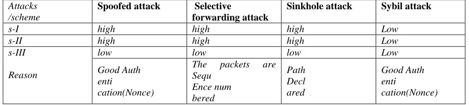
VII. POSSIBLEATTACKS
7.1. Spoofed, altered, or replayed routing Information
loops, attract or repel network traffic, extend or shorten source routes, generate false error messages, partition the network, and increase end-to-end latency. The standard solution for this attack is authentication. i.e., routers will only accept routing information from valid routers.
7.2. Selective forwarding attack
Multi-hop mode of communication is commonly preferred in wireless sensor network data gathering protocols. Multi-hop networks assume that participating nodes will faithfully forward and receive messages. However a malicious node may refuse to forward certain messages and simply drop them, ensuring that they are not propagated any further. This attack can be detected if packet sequence numbers are checked properly and continuously in a conjunction free network. Addition of data packet sequence number in packet header can reduce this attack.
7.3 Sinkhole attack
By sinkhole attack, the adversary tries to attract early all the traffic from a particular area through a compromised node. A compromised node which is placed at the centre of some area creates a large “sphere of influence”, attracting all traffic destined for a base station from the sensor nodes. The attacker targets a place to create a sinkhole where it can attract the most
traffic, possibly Base User Station. Several sensor network routing algorithms rely on implicit or explicit link layer acknowledgements. Due to the inherent broadcast medium, an adversary can spoof link layer acknowledgments for “overheard” packets addressed to neighbouring nodes. Protocols that choose the next hop based on reliability issues are susceptible to acknowledgments spoofing. This results in packets being lost when travelling along such links. The goal includes convincing the sender that a weak link is strong or that a dead or disabled node is alive. Since packets sent along weak or dead links are lost, an adversary can effectively mount a selective forwarding attack using acknowledgement spoofing by encouraging the target node to transmit packets on those links communication.
7.4 Sybil attack
In a Sybil attack, an attacker can appear to be in multiple places at the same time. This can be convinced by reading fake identities of nodes located at the edge communication range. Multiple identities can be occupied within the sensor network either by fabricating or stealing the identities of legitimate nodes. Sybil attacks can pose a significant threat to geographic routing protocols. Proper authentication can defend it.
Attacks /scheme
Spoofed attack Selective
forwarding attack
Sinkhole attack Sybil attack
s-I high high high Low
s-II high high high Low
s-III
Reason
low low low Low
Good Auth enti
cation(Nonce)
The packets are
Sequ Ence num bered
Path Decl ared
Good Auth enti
[image:8.612.69.544.334.441.2]cation(Nonce)
Table :6 attacks verses schemes
VIII. PERFORMANCEANALYSIS
In an attempt to thoroughly investigate and profile the energy consumption in a WSN, we performed a wide set of simulation scenarios. Every node in a WSN consumes energy mainly for transmission and reception purposes. It transmits routing and data messages and thus the energy consumption depends on the node location and the data messages it generates or forwards. To quantify these dependencies, we have run a scenario set with no malicious nodes in the network,100 nodes are placed in a 10x10 grid. Ten nodes transmit data to the base station. The simulated application issues one packet of 10K bytes every two seconds while the Beacon interval is 0,5 seconds . We have measured the energy consumption of nodes A, B, E, F,G . Based on the obtained results, we have calculated the energy consumption for the case where both data and routing messages circulate in the network and the energy consumption when only routing messages are exchanged.
In this analysis, we consider two parameters that decide the outcome of our model. They are
1. Throughput 2. Latency.
The difference between the time after construction of packets before sends and time after reception of all packets is called latency. The ratio of total no of packets transmitted to the total latency for those packets transmitted under current cluster head is called throughput.
Latency = Time after construction of packets - Time after reception of packets
Throughput = Total no of packets transmitted Total latency
Packets transmitted (session 1) = 100000 Latency = 3000ms
Packets transmitted (session 1) = 109583 Latency = 4000ms
Throughput = 100000+109583 3000+4000 =29.940%
Fig: 8 Node Registration With Cluster Head
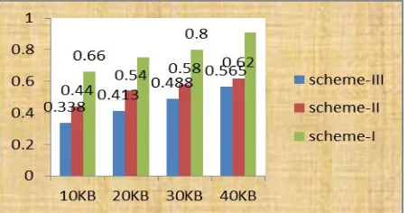
The Encryption algorithm used for encryption is DES (Data Encryption Standard).The energy consumed for encryption is tabulated for varying message size. The proposed scheme-III consumes less energy for encryption. Total Energy consumed is also calculated with the energy spent for receive and transmit of message.
Fig: 9 Energy consumed for Encryption for three schemes.
[image:9.612.333.557.57.200.2]The Decryption algorithm used for Decryption is DES (Data Encryption Standard).The energy consumed for Decryption is tabulated for varying message size. The proposed scheme-III consumes less energy for Decryption. Total Energy consumed is also calculated with the energy spent for receive and transmit of message
[image:9.612.51.282.344.491.2]Fig 10 Energy consumed for Decryption for three schemes
Fig 11 Total Energy consumed for three schemes
IX. CONCLUSIONANDFUTUREWORK
In this paper the three schemes were compared and their efficiency through various metrics were tabulated in table .This paper investigates and evaluates the most important key management schemes in wireless sensor networks. Namely, scheme-III, Scheme-I, scheme-II are explained and evaluated against metrics and attacks using JAVA simulator. Our future research directions involve comparing more key management schemes using different metrics and larger network sizes.
REFERENCES
[1] L. Eschenauer and V. D. Gligor, “A key-management scheme for distributed sensor networks,” in Proceedings of the 9th ACM conference on
Computer and communications security, pp. 41–47, Washington, DC, USA: ACM Press, 2002
[2] Ibriq, J., and Mahgoub, I. (2007), „A Hierarchical Key Establishment Scheme for Wireless Sensor Networks‟. 21st International Conference on Advanced Networking and Applications, pp: 210-219
[3] M. Eltoweissy, M. Heydari, L. Morales, and H.Sudborough, “Combinatorial Optimization for Key Management in Secure Multicast Environments,” Journal of Network and System Management,12(1):33-50, 2004.
[4] Kaplantzis,S.,(2006)“SecurityModelsforWirelessSensorNetworks”,http://m embers.iinet.com.au/~souvla/transferfinal-ev.pdf.
[5] Sohrabi, K., Gao, J., Ailawadhi, V., and Pottie, G. J., (2000) “Protocols for Self- Organization of a Wireless Sensor Network”, IEEE Personal Communications, pp. 16-27
[6] Woo, A. and Culler, D., (2001) “A Transmission Control Scheme for Media Access in Sensor Networks”, Proceedings of the IEEE International Conference on Mobile Computing and Networking (MobiCom 2001), Rome, Italy.
[7] Shih, E., Cho, S., Ickes, N., Min, R., Sinhala., Wang, A. & Chandrakasan, A., (2001)“Physical layer driven protocol and algorithm design for energy-efficientess sensor networks”, Proceedings of the 7th Annual International Conference on Mobile Computing and Networking, Rome, Italy, pp.272-287.
[8] G. Jolly, M. Kuscu, P. Kokate, and M. Younus, “A150 International Journal Of Intelligent Control And Systems, Vol. 13, No. 2, June 2008Low-Energy Key Management Protocol for Wireless Sensor Networks,” in: Proceedings of the 8th IEEE, Symposium on Computer and Communications (ISCC), Antalya, 335-340, 2003.
[9] Committee on National Security Systems (CNSS), (2006) National Information Assurance Glossary, NSTISSI,No. 4009. Journal of Theoretical and Applied Information Technology© 2005- 2010JATIT.Allrights reserved.www.jatit.org
[image:9.612.56.282.598.716.2][11] Walters, J. P., Liang, Z., Shi, W., and Chaudhary, V., (2007) “Wireless sensor network security - a survey”, Security in Distributed, Grid, Mobile, and Pervasive Computing, Auerbach Publications, CRC Press.
[12] Stallings, W., (2000) Cryptography and Network Security Principles and Practice, Cryptography Book, 2nd Edition, Prentice- Hall, 0-13-8690170. [13] Karlof, C., and Wagner, D., (2003) “Secure Routing in Sensor Networks:
Attacks and Countermeasures”, SNPA, pp. 1-15.
[14] Saxena, M., (2007) “Security in Wireless Sensor Networks – A Layer based Classification”, Technical Report [CERIAS TR 2007-04], Center for Education and Research in Information Assurance and Security - CERIAS, PurdueUniversity.pages.cs.wisc.edu/~Massena/papers/2007-04-cerias.pdf [15] fernades introduction to Wireless Sensor
NetworksReport”,Universityofrento.http://dit.unitn.it/~fernand/downloads/i wsn.pdf
[16] Siahaan, I. and Fernandes, L. (2008), “Secure Routing in Wireless Sensor Networks”, University of Trento
http://dit.unitn.it/~fernand/downloads/IWSNSlides.pdf
[17] Zia, T. A., (2008), “A Security framework for Wireless SensorNetworks”.http://ses.library.usyd.edu.au/bitstream/2123 2258/4/02whole.pdf
[18] Heinemann, W., Kulik, J. & BalakrishnaH., (1999) “Adaptive protocols for information dissemination in wireless sensor networks”, The Proceedings of the 5th AnnualACM/IEEE International Conference on Mobile Computing and Networking(MobiCom_99), Seattle, WA.
[19] Yoneki, E. & Bacon, J., (2005) “A survey of Wireless Sensor Network technologies: research trends and middleware‟s role”, technical report. [20] Intanagonwiwat, C., Govindan, R. & Estrin,D., (2003) “Directed Diffusion
for Wireless Sensor Networking”, IEEE/ACM Transaction on Networking, VOL. 11, NO. 21] Ye, F., Chen, A., Lu, S. and Zhang, L., (2001) “A Scalable Solution to Minimum Cost Forwarding in Large Sensor networks”,
Proceedings of the 10th IEEE International Conference on Computer Communications and Networks (ICCCN'01).
[21] C.-Y. Chong and S. P. Kumar, “Sensor networks: Evolution, opportunities, and challenges,” in Proc. IEEE special issue on Sensor Networks and Applications,vol. 91, no. 8, Aug. 2003, pp. 1247–1256.
[22] Blundo, C.; Santis, A.D.; Herzberg, A.; Kutten, S.; Vaccaro, U.; Yung, M. Perfect-Secure Key Distribution of Dynamic conferences. In Proceedings of Advances in Cryptography, BalatonfÜred, Hungary; pp. 471–486. [23] Cahn, N.T.; Lee, Y.-K.; Lee, S.Y. HGKM - a group-based key management
scheme for sensor networks using deployment knowledge. In Proceedings of Sixth Annual Conference on Communication Networks and Services Research (CNSR), Halifax, Nova Scotia, May 2008; pp.544-551
[24] Lin SHEN and Xiangquan SHI “A Dynamic Cluster-based Key Management Protocol in Wireless Sensor Networks”, International Journal Of Intelligent Control And Systems, Vol. 13, No. 2, June 2008, 146-151. [25] M. Moharram, R. Mukkamala, and M. Eltoweissy,“TKGS: Threshold-based
Key Generation Schemefor Wireless Ad Hoc Networks,” in: Proceedings of the IEEE International Conference on Computer Communications and Networking (ICCCN’2004),Chicago, IL, 31-36, October 2004.
AUTHORS
First Author – D.C.Jullie Josephine, Joe Suresh Engineering College,[email protected]
Second Author – Dr.T.Jebarajan, Principal, Kings Engineering College, Chennai