bandwidth in comparison to wired networks but in spite of this constraint wireless networks are becoming popular day by day on account of their flexibility, mobility as well as inexpensive physical medium (air). This paper aims to simulate wireless local area network. The performance of the network is evaluated using optimized network engineering tool, OPNET 14.5 modeler,over four major physical layer technologies Infra-Red , Direct Sequence Spread Spectrum DSSS, Frequency Hopping Spread Spectrum FHSS and Orthogonal Frequency Division Multiplexing OFDM at multiple transmissionrates,1Mbps,2Mbps,5.5Mbps,6Mbps, 9Mbps,11Mbps, 36Mbps,48Mbps, 54Mbps. DSSS can use 1,2,5.5,11 Mbps rates. FHSS and IR are able to operate at 1or 2 Mbps rates, while OFDM is capable to operate at 6, 9,11,36,48 or 54 Mbps rate.A trade-off exists between the selected data rate and the physical technology. It is founded that at some transmission rate, the OFDM technology delay is better than in DSSS. FHSS delay is less than DSSS delay. IR delay is better than FHSS and DSSS delay. In addition, for one physical layer technology the delay can be reduced by increasing the transmission rate of the channel.
General Terms
Throughput, delay, loads.
Keywords
Wireless LAN, IEEE 802.11 OPNET.
1.
INTRODUCTION
The field of wireless local area networks (WLANs) is being widely studied and used in various emerging research domains such as mobile and pervasive computing, where WLANs provide high-speed wireless connection and support accessing information from anywhere and anytime. WLANs[1-3] support a wide range of applications, which may include simple applications such as web browsing, file transferring, etc. and the other ones, for instance, real-time multimedia applications (e.g., video streaming and video conferencing). IEEE 802.11is a vital standard for wireless LAN, which adopts the standard 802 logical link control (LLC) protocol that is further divided into two sub layers: physical layer (PHY) and medium access control (MAC) layer. This configuration provides optimized functionality for wireless communication. Initially 802.11 had two physical layers: Direct Sequence Spread Spectrum (DSSS) and Frequency Hopping Spread Spectrum (FHSS) and later, the physical layer have been categorized into three types with different physical characteristics and frequency spectrum. The physical characteristic of 802.11a and 802.11g are identical – both are based on OFDM and support data rate of 54 Mbps.
transmission rate from 1 to 11 Mbps. 802.11a has significant advantage due to the wide range spectrum of 5 GHz, having more number of independent channels. Both 802.11b and 802.11g are compatible with each other as both operates on 2.4 GHz spectrum, but this may cause degradation in system performance as 2.4 GHz is a small band spectrum with a lesser number of independent channels. The main objective of the work presented in this paper is to evaluate the performance ofwireless local area networkespecially end-to-end delay, media access delay, load, traffic received and traffic sent.Infra-Red, Direct sequence, frequency hopping and OFDM has been utilized with different settingfor comparison between them. The network setuphave been simulated using OPNET 14.5 modeler.The simulation consists of sixteen scenarios. One scenario differs from the other scenario either in the physical layer technology or (and) transmission rate or (and) in data generation rate.
2.
RELATED WORK
There exists a large body of research on wireless network, such as [4, 5, 6, and 7]. In [4], performance analysis of the Wireless and Wired computer networks through simulation has been attempted using OPNET as simulating tool.
The authors [5] simulated wireless LAN standard through the delivery of video traffic. The authors [6] suggest that Wireless LAN performance can be improved by fine tuning parameters such as fragmentation threshold, and buffer size. In [7], performance of 802.11 WLAN scenarios have been evaluated in OPNET Modeler 14.5.Throughput of the WLAN is evaluated in the presence of high priority traffic as well as low priority traffic, generating data simultaneously
3.
EXPERIMENTAL SETUP
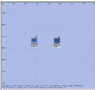
Fig.1: The Proposed Network
[image:2.595.316.543.71.252.2]Table1includes the traffic generation parameters and Table 2 includesWLAN parameters for this work. The traffic generation parameters are selected such thatthe generation rate of data is 1Mbps. The results are shown in figures (2-19)
Table 1.Traffic Generation Parameters.
Attribute Value
Start Time (seconds) Constant (10) On State Time (seconds) Constant (600)
[image:2.595.314.543.285.467.2]Off State Time (seconds) Constant (0) Interval Time (seconds) 0.004 Packet Size (bytes) 512 Stop Time (seconds) Never
Table 2. WLAN Parameters
Attribute Value
BSS Identifier Auto Assigned Access Point Functionality Disabled
Physical Characteristics Infra-Red, Direct Sequence, FrequencyHopping,OFDM Data Rate 1Mbps, 2Mbps, 5.5 Mbps,
6Mbps, 9Mbps, 11Mbps, 36Mbps, 48Mbps, 54Mbps
Chanel Setting Auto Assigned Buffer Size (bits) 2560000
3.1
WLAN Delay
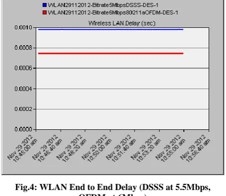
Global statistics of WLAN delay is gathered for ten minutes of simulation time and can be observed in the following figures. WLAN delay represents the end to end delay of all the packets received by the wireless LAN MACs of all WLAN nodes in the network and forwarded to the higher layer.This delay includes medium access delay at the source MAC, reception of all the fragments individually, and transfers of the frames via AP (Access Point), if access point
Fig.2: WLAN End to End Delay with DSSS Physical Layer Technology.
Fig 3: WLANEnd to End Delay with OFDM Physical Layer Technology.
[image:2.595.49.288.324.444.2]Fig.4: WLAN End to End Delay (DSSS at 5.5Mbps, OFDM at 6Mbps)
Fig.5:WLAN End to End Delay (DSSS at 2Mbps, Frequency Hopping at 2Mbps, IR at 2Mbps)
[image:3.595.53.281.74.271.2]Fig.6: WLAN End to End Delay (DSSS at 11Mbps, Ex802.11g at 11Mbps)
Fig 7: WLAN End to End Delay for the Proposed Scenarios
3.2
Media Access Delay
[image:3.595.52.282.370.668.2]Fig.8: Media Access Delay and End to End Delay with DSSS Physical Layer Technology.
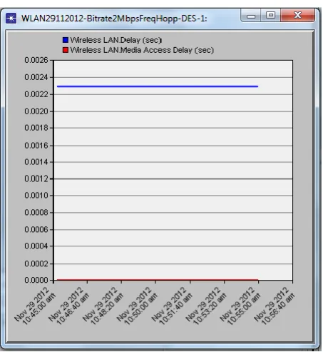
[image:4.595.54.281.341.588.2]Fig.9: Media Access Delay and End to End Delay with Frequency Hopping Physical Layer Technology.
Fig.10: Media Access Delay and End to End Delay with OFDM Physical Layer Technology
3.3
Traffic Received, Traffic Sent, Data
Dropped, Throughput and Load
The traffic received, traffic sent, data dropped,throughput and load are shown in figures (11-19).
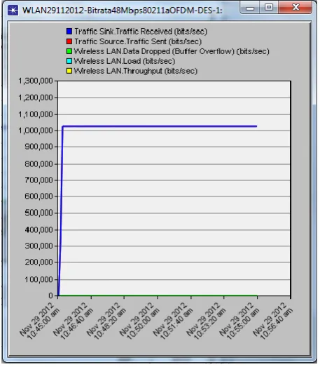
The traffic generation parameters for the proposed system are selected in a way such that the generation rate of data is 1Mbps. So the throughput, load, traffic received and traffic sent are 1Mbps for the proposed system and no dropped data as shown in figures (11-13). In the network with 1Mbps bite rate (fig.15), there is dropping in the data. The load on the network equal to 1Mbps but the throughput is less than this value (fig.14). The traffic receivedcan be improved (fig.16) by tuning the traffic generation parameters.
[image:4.595.316.543.500.734.2]Fig.12: Traffic, Load, Throughput, Data Dropped for Frequency Hopping physical layer technology at 2 Mbps
[image:5.595.54.282.71.333.2]Fig.13: Traffic, Load, Throughput, Data Dropped for OFDM physical layer technology at 48Mbps
Fig.14: Load, Throughput for DSSS physical layer technology at 1 Mbps
[image:5.595.314.542.355.607.2] [image:5.595.53.282.397.659.2]Fig.16:Traffic Received, Traffic Sent, Data Dropped, Throughput, Load for DSSS physical layer technology at
1Mbps after tuning traffic generation parameters
Fig.17: Throughputfor DSSS physical layer technology at 1Mbps before (DSSS) and after (DSSS2) tuning the traffic
[image:6.595.54.281.69.336.2]generation parameters
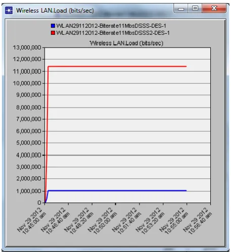
Fig.18: Load for DSSS physical layer technology at 1Mbps before (DSSS) and after (DSSS2) tuning the traffic
generation parameters
Fig.19: WLAN end to end delay for DSSS physical layer technology at 1Mbps before (DSSS) and after (DSSS2)
[image:6.595.54.281.373.624.2] [image:6.595.314.541.377.627.2][1] Jeffry, R., Jackie, A. 2001 Designing a wireless network [2] Dean A. Gratton 2007 Developing practical wireless
applications