6
I
January 2018
Digital Modulation Techniques for Performance
Exploration of Optical Wireless Channels
Javed Ashraf 1, Prof. (Dr.) Anil Kumar 2, Prof. (Dr.) Mumtaz A. Khan3
1
Deptt. of EE&CE Al-Falah University Faridabad (Haryana), India
2
Vice Chancellor Al-Falah University Faridabad (Haryana), India
3
Director Mewat Engineering College Palla, Nuh, Mewat, Haryana-122107
Abstract: There are many modulation techniques which are used for optical wireless communication. For getting high average-power-efficiency, On off Keying Modulation (
M
O.O.K) and Pulse position modulation (M
P.P.M) are implemented extensively in optical wireless communication. In optical wireless communication Differential pulse position modulation (M
D.P.P.M), Digital pulse interval modulation (M
D.P.I.M) and Double header pulse interval modulation (M
D.H.P.I.M) are three new modulation schemes which may become the replacement ofMP.P.M because of their better results in power efficiency and bandwidth efficiency. In this research paper, the power efficiency and bandwidth of the typical modulation schemes such asO.O.K
M ,MP.P.M, MD.P.I.Mand MD.H.P.I.Mare analyzed by taking the combination of the features of the wireless optical channel. Simulation has been done using MATLAB software. Analysis and simulation shows that MD.P.I.M and MD.H.P.I.M are more applicable for the future of optical wireless communication. When bit resolutions increases in MD.H.P.I.M, MD.P.I.M,MO.O.Kand
P.P.M
M modulation schemes, corresponding symbol length increases. Hence the bandwidth requirement increases but the average optical power requirement decreases.
Keywords: MD.H.P.I.M,
M
D.P.I.M,MO.O.K,MP.P.M, Optical wireless communication.I. INTRODUCTION
Optical wireless communications have the advantages of both optical fiber and mobile communication. It uses broad bandwidth. Therefore, the research work in the area of optical wireless communication in recent years is getting more optical range. The optical wireless communication leads to signal attenuation, the reason behind it being that it is impacted by scattering, turbulence and atmospheric absorption in the surroundings. The human eye safety limits the average transmission power in wireless optical communication [1], [2]. Thus, to overcome this problem an appropriate modulation technique is required [10], [11].
II. CLASSIFICATION OF OPTICAL WIRELESS MODULATION TECHNIQUES
A. ON OFF KEYING DIGITAL PULSE TIME MODULATION TECHNIQUES
MO.O.K
MO.O.K
is the elementary scheme that is implement in wireless infrared transmission, and due to its simplicity, it is the mostcommonly used modulation schemes for I.M/D.D in optical communication. InMO.O.K technique, the transmission of pulse is done when the code bit is binary ‘1’ in a fixed time slot and when there is no pulse then the code bit is binary ‘0’. For getting a stream of pulses before transmitting the information, it is translated to a definite code for example Return to Zero
MR.Z
, Manchester, or NonReturn to Zero
MN.R.Z
codes. In an Additive White Gaussian Noise
AA.W.G.N
channel, for achieving same level of bit errorperformance, MO.O.K with MR.Z signalling needs nearly 5logγ (dB) of optical power greater than that is required in
O.O.K
M withMN.R.Z.
Error of y Probabilit
PP.O.E , forMN.R.Z MO.O.K, with no dispersion is given by [2]
) 1 ...( R
N P R Q P
B.R N.S.D
A.T.P R.P.T M.F
P.O.E_OOK
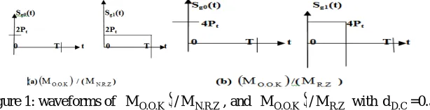
These pulses can have different duty cycle (dD.C). When using a dD.C<1, the desired bandwidth is raised by a factor of 1/duty cycle
(dD.C) whereas the average power need declines. This is the reason why in infrared systems, MO.O.K with MR.Z pulses is
commonly used. Figure 1 shows the waveforms of
MO.O.K
/MN.R.Z, and
MO.O.K
/MR.Z with dD.C=0.5 [6].
M
P.P.M
scheme is [image:3.612.160.467.150.229.2]more efficient for smaller dD.C [4].
Figure 1: waveforms of
MO.O.K
/MN.R.Z, and
MO.O.K
/MR.Z with dD.C=0.5.There are different types of forward error control methods that are currently in use and are recommended for reducing the Bit Error Rates (BB.E.R) [10]. In diffuse optical links, the achievable data rate is restricted by Multipath induced dispersion. For instance,
withMO.O.K, a data rate of up to 100 Mbs_1 is not practicable when signalling takes place inside a media which is having a
normalized delay spread up to the value of 0.6 [10]. This is the reason of using, in half duplex communication, a paltry data rate of
up to 1.150 Mbs_1 with a 25 percent
d
D.C in the serial physical layer standards by the IrDA [3], [4]. ForMO.O.K, the MaximumLikelihood Sequence Detector (MM.L.S.D ) should be adopted in a multipath channel for achieving optimal results. But the
implementation of MM.L.S.D is impractical because of the prohibitive processing time and its complexity. Thus, a feasible aspect is
utilization of an equalizer though it gives sub-optimal data rates. Using a Decision Feedback Equalizer
(DD.F.E) with theMO.O.K, even in the most dispersive channel, makes the up till now unfeasible 100 Mbs_1 data rate a possibility
[10] There are many other equalization techniques with their detailed analysis that have been proposed for MO.O.Kscheme [1], [3] and [10].
B. SINGLE PULSE POSITION MODULATION TECHNIQUES (LPPM) P.P.M
M is an orthogonal modulation scheme for a wireless optical communications. When its comparison is done with all other
remaining modulation schemes it is found that among them MP.P.M has the highest power efficiency. The aspect of having higher
efficiency makes it applicable for handheld devices because one of the major factors in such type of devices is lower power consumption. It is commercially used in dedicated communication like laptop, palmtop, IrDA, etc. MP.P.Mis defining to contain L
slots in a particular symbol (mark) time. So inMP.P.M
, optical power transmission is constant within only one of chips and power in the remaining (LSL-1) chips is zero. The un-coded 32-MP.P.Mhas smaller average power-efficiency than coded 16-MP.P.M .
Similarly, inMP.P.M, un-coded 16-MP.P.M have lesser average power-efficiency than coded 8-MP.P.M. MP.P.Mpulse duration is
shorter by a factor LSL /
B
BRe than theM
O.O.K pulse duration for achieving the same throughput. It achieves higher powerefficiency by a factor of LSL /
B
BRe but this is achieved by increasing the bandwidth requirement.The Slot Error Rate
S.E.R
P
of MP.P.M is given by [3] and [4]) 2 ...( R N
P R .B L 2 1 Q P
B.R N.S.D
A.T.P R.P.T BRe S.L M.F
S.E.R_PPM
From the above equation it is clear that the average power required by the MP.P.M for achieving similar error performance, is lower
by a factor of (0.5 LSL.BBRe)1/2 than that required by MO.O.K.
Another key advantage of MP.P.M is that if it is compared with MO.O.Kit has a much lower DC component .This factor is beneficial
The two factors that limits the performance of the MP.P.M technique are the symbol and slot synchronization and the multipath
induced Inter Symbol Interference (II.S.I). The acquired power penalty in diffuse infrared links due to II.S.I is lesser in comparison
of the MO.O.K modulation technique due to the existence of the LSL -1 empty slot. A linear equalizer and decision feedback
equalizer, both are used in [3] and [10] for minimizing the induced
I
I.S.I in diffused links.C. DIGITAL PULSE INTERVAL MODULATION
MD.P.I.M
D.P.I.M
M is a modulation schemes that disposes of all the empty time slots presented by each symbol hence showing a higher
transmission capacity. This technique does not need symbol synchronization given that every symbol starts with a pulse [12], [13]. The prearrangement of data is done among neighboring pulses as a number of discrete time intervals or slots. The average optical power of pre arranged pulse stream usingMD.P.I.M is much better than aMD.P.I.M encoded pulse stream because of having a shorter
symbol length (LS.L.). The only thing it requires is clock synchronization without symbol synchronization [5]. The separation of
symbol length (LS.L.) ofMD.P.I.M into protected and unprotected slots is possible inMD.P.P.M.
For decreasing the impact of Inter Symbol Interference (ISI) successfully, one protected slot is mainly adopted with protected
D.P.I.M
M modulation schemes [7], [8]. The modulation marks,SD
,which is a decimal number and is communicated by the symbol, hold D+2 time slots. For communicating the information, the pulse adds a protected empty slot and D blank slots after each initial time slot L. The formatting of the pulse time slot is done for receiving the demodulation. Demodulation is done by only counting the empty time slot and subtracting one of them [6].
D. DOUBLE HEADER PULSE INTERVAL MODULATION
(
M
D.H.P.I.M)
Double header pulse interval modulation MD.H.P.I.Mwas at first initially proposed in 1999. It comprises of lesser transmission
bandwidths in comparison to
M
P.P.M modulation scheme and thus providing higher bit rate. It moreover has incorporated framesynchronization facility [3], [5]. MD.H.P.I.Mis further more troublesome as the symbol accepts two different sort of starting pulse
The time slot incorporated each symbol is as well mutative. The symbol is made by a head slot in addition to empty time slots
follow. Head time slot is built-in by
β
I+1 time slots where βIis an Integer. Two types of Headers are permitted, i.e. H1 and whereH1 is the preliminary pulse width withβI/2 time slot, followed through (βI /2) +1 confined time slots; pulse width is a time slot, followed via one time slot [5]. If k is less than 2M-1 after that head time slot of symbol SD isH , or else it be1 H . 2
III. COMPARISONSOFVARIOUSMODULATIONTECHNIQUES
Individual modulation schemes such asMP.P.M, MO.O.K, MD.H.P.I.Mand MD.P.I.Mare compared by differentiating with respect to
power and bandwidth efficiency.
A. POWER AND EFFICIENCY OF DISTINCT MODULATION TECHNIQUES:
1) PROVISION OF BANDWIDTH FOR DISTINCT MODULATION TECHNIQUES [9],[10]
Band width provision for MD.H.P.I.M, MD.P.I.M, MP.P.M and MO.O.Kare given as:
3 ... R R
β
R 1 2β
2
B B.R
B.Re I
B.R I
1 B.R R
.I.M req_D.H.P.
4 ... R 2B1 L
B B.R
B.Re SL req_DPIM
5 ... R BL
B B.R
B.Re SL req_PPM
6 ... RB B.R
2) POWER EFFICIENCY NEED FOR MP.P.M [16] The power efficiency need for
η
PE_PPMsystem is
L
L log
...(7)2 η 2 SL SL PPM
PE
3) POWER EFFICIENCY NEED FOR MO.O.KSYSTEM [13],[14]
Power efficiency need for MO.O.Ksystem is
P
....(8) Q 2R N R η P.O.E_OOK 1 2 R.P.D N.S.D B.R _OOKPE
4) POWER EFFICIENCY AND AVERAGE OPTICAL POWER REQUIRED FOR MD.H.P.I.MSYSTEM [13],[14]
Power efficiency as well as average optical power for MD.H.P.I.Msystem is
2 2β 1
2B
...(9)9β η B.Re I 1 B.R B 2 I DPIM PE e
P
..(10)Q L M 16R R 2N 9β
P P.S.E_DH PIM
1 PIM DH 2 R.P.D B.Re N.S.D 2 I PIM avgDH
5) POWER EFFICIENCY AND AVERAGE OPTICAL POWER REQUIRED FOR MP.P.M[13],[14] The power efficiency of MP.P.M is
11 .... ) L (log ) (L 4 η SL 2 SL PPMPE
Hence the average power need for
M
P.P.Mis
R
(L )
Log L
Q
P
...(12)R 2N
P P.S.E_PPM_H
1 SL 2 SL 2 R.P.D B.R N.S.D avg_PPM
6) POWER EFFICIENCY AND POWER OF A MD.P.I.MSYSTEM [14],[15]
Power efficiency and Power of an optical system for aMD.P.I.Mis
L
(L 1)log ...(13) 8 η 2 SL SL DPIM P
P
...(14) Q ) (L log ) L ( ) (R ) )(R 2(N P P.S.E_DPIM 1 SL 2 DPIM SL 2 R.P.D B.R N.S.D avg_DPIM IV. SIMULATIONRESULTS
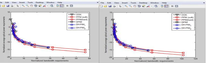
Figure 2 & 3 Normalized bandwidth and Normalized average optical power requirements at bit resolution =1:3 and 1:4
Figure: 4 & 5 Normalized bandwidth and Normalized average optical power requirements at bit resolution =1:5 and 1:6
Figure: 6 & 7 Normalized bandwidth and Normalized average optical power requirements at bit resolution =1:7 and 1:8
[image:6.612.121.500.79.198.2] [image:6.612.120.502.241.361.2] [image:6.612.124.503.401.541.2] [image:6.612.105.521.580.707.2]Figure: 10 & 11 Normalized bandwidth and Normalized average optical power requirements at bit resolution =1:11 and 1:12
[image:7.612.119.503.110.385.2]Figure 12 & 13 Normalized bandwidth and Normalized average optical power requirements at bit resolution =1:13 and 1:14
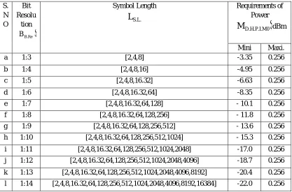
Table: 1 Comparative Statement of Required Power of distinct Modulation Techniques S.
N O
Bit Resolu
tion
BB.Re
Symbol Length
S.L.
L
Requirements of Power
M
D.H.P.I.M0
dBmMini Maxi.
a 1:3 [2,4,8] -3.35 0.256
b 1:4 [2,4,8,16] -4.95 0.256
c 1:5 [2,4,8,16.32] -6.63 0.256
d 1:6 [2,4,8,16.32,64] -8.35 0.256
e 1:7 [2,4,8,16.32,64,128] - 10.1 0.256
f 1:8 [2,4,8,16.32,64,128,256] - 11.8 0.256
g 1:9 [2,4,8,16.32,64,128,256,512] - 13.6 0.256
h 1:10 [2,4,8,16.32,64,128,256,512,1024] - 15.3 0.256
i 1:11 [2,4,8,16.32,64,128,256,512,1024,2048] -17.0 0.256
j 1:12 [2,4,8,16.32,64,128,256,512,1024,2048,4096] -18.7 0.256
k 1:13 [2,4,8,16.32,64,128,256,512,1024,2048,4096,8192] -20.4 0.256
[image:7.612.99.516.445.720.2]Requirements of Power
M
D.H.P.I.M1
(dBm)
Requirements of Power
M
D.P.I.M
(dBm)
Requirements of Power
M
O.O.K
(dBm)
Requirements of Power
M
P.P.M
HARD(dBm)Requirements of Power
M
P.P.M
SOFT(dBm)Mini. Maxi. Mini. Maxi. Mini. Maxi. Mini. Maxi. Mini. Maxi.
-.881 2.386 -2.64 2.130 -2.93 5.108 -3.90 1.505 -5.39 0
-2.31 2.386 -4.65 2.130 -2.93 5.108 -6.02 1.505 -7.53 0
-3.83 2.386 -6.57 2.130 -2.93 5.108 -8.01 1.505 -9.52 0
- 5.46 2.386 - 8.44 2.130 -2.93 5.108 - 9.91 1.505 - 11.41 0
- 7.14 2.386 - 10.3 2.130 -2.93 5.108 - 11.7 1.505 - 13.3 0
- 8.86 2.386 - 12.0 2.130 -2.93 5.108 -13.5 1.505 - 15.6 0
- 10.6 2.386 - 13.8 2.130 -2.93 5.108 - 15.3 1.505 - 16.8 0
- 12.3 2.386 - 15.5 2.130 -2.93 5.108 -17.0 1.505 - 18.5 0
-14.0 2.386 -17.2 2.130 -2.93 5.108 -18.8 1.505 -20.3 0
-15.7 2.386 -18.9 2.130 -2.93 5.108 -20.4 1.505 -22.0 0
-17.4 2.386 -20.6 2.130 -2.93 5.108 -22.1 1.505 -23.6 0
-19.0 2.386 -22.3 2.130 -2.93 5.108 -23.8 1.505 -25.3 0
Table: 2 Comparative statement of Required Normalized Band Width of distinct Modulation Techniques: S.
N O
Bit Resolu
tion
BB.Re
Symbol Length
S.L.
L
Requirements of Band Width
For
M
D.H.P.I.M0
Mini Maxi
a 1:3 [2,4,8] 2.3333 4
b 1:4 [2,4,8,16] 2.3333 4
c 1:5 [2,4,8,16.32] 2.3333 4
d 1:6 [2,4,8,16.32,64] 2.3333 5.8333
e 1:7 [2,4,8,16.32,64,128] 2.3333 9.5714
f 1:8 [2,4,8,16.32,64,128,256] 2.3333 16.375
g 1:9 [2,4,8,16.32,64,128,256,512] 2.3333 28.778
h 1:10 [2,4,8,16.32,64,128,256,512,1024] 2.3333 51.500
i 1:11 [2,4,8,16.32,64,128,256,512,1024,2048] 2.3333 93.363
j 1:12 [2,4,8,16.32,64,128,256,512,1024,2048,4096] 2.3333 170.91
k 1:13 [2,4,8,16.32,64,128,256,512,1024,2048,4096,8192] 2.3333 315.30
l 1:14 [2,4,8,16.32,64,128,256,512,1024,2048,4096,8192,16384] 2.3333 585.35
Requirements of Band Width
For
M
D.H.P.I.M1
Requirements of Band Width
For
M
D.P.I.M
Requirements of Band Width
For
M
O.O.K
Requirements of Band Width
For
M
P.P.M
Mini. Maxi. Mini. Maxi. Mini. Maxi. Mini. Maxi.
The Packet Transmission Rate, Average Symbol Length, Transmission Capacity and Bandwidth Requirement of
MP.P.M
,(MD.P.PM),
MD.P.I.M
, (MD.H.P.I.M),(MM.D.P.I.M) and (MD.A.P.P.M) is discussed below in Table 3.Table: 3 Modulation
scheme D.A.P.P.M
M
M
D.P.I.M/M
D.P.PMNormalised Bandwidth Requirement to
N.R.Z-
M
O.O.K
PA BRe PA 1 B B.RA
2B
A
2
R
BRe
BRe B B.R
2B
3
2
R
BRe
Packet transmission
rate
PA
1 B N.T.P DAPPM req PA BRe
A
2
N
_
B
A
2B
BRe
N
2
3
_
B
2B
BRe B N.T.P P.P.M req BRe
Average symbol length
PA PA 1 -B2A
A
2
BRe
2
3
2
BBRe
Transmission Capacity PA B B PA BRe
A
2
2
A
2B
BRe BRe
B
2B req 2 BRe
3
2
1
2
B
4B
BRe BRe
Modulationscheme M.D.P.I.M
M
M
P.P.MM
D.H.P.I.MNormalised Bandwidth requirement to
N.R.Z
M
O.O.K
BRe 1 B B.R2B
3
2
R
BRe
M
2
R
MB.R
M
β
1
2
β
2
R
I I 1 MB.R
Packet transmission
rate
N
2
3
2MB
1 M P.K.T req
M P.K.T P.P.M req2
N
_
MB
2
2
β
1
N
MB
β
I 1 M P.K.T req I
Average symbol length
2
3
2
M-1
2
M
2
1
2
β
2
I 1 -M
TransmissionCapacity M1
2
1 M REQ 2
3)
(2
1
2
B
4M
M req 22
B
M
2 I 1 M I 1 M REQ 2 I
1)
2
β
(2
β
2
B
M
2
β
1.500 3 1.2500 2.125 0.095 3.8460 2 4
1.500 3 1.2500 3.300 0.095 3.8460 2 6.400
1.500 3.0833 1.2500 5.4167 0.095 3.8460 2 10.667
1.500 4.9286 1.2500 9.2143 0.095 3.8460 2 18.286
1.500 8.3125 1.2500 16.063 0.095 3.8460 2 32
1.500 14.500 1.2500 28.500 0.095 3.8460 2 56.889
1.500 25.850 1.2500 51.250 0.095 3.8460 2 102.40
1.500 46.773 1.2500 93.136 0.095 3.8460 2 186.18
1.500 85.542 1.2500 170.70 0.095 3.8460 2 341.33
1.500 157.73 1.2500 315.11 0.095 3.8460 2 630.15
V.CONCLUSION
In this research work, a vast view is represented of various modulation schemes that are compatible for wireless optical
communication systems likeMO.O.K
M
P.P.M,M
D.P.I.Mand MD.H.P.I.M. This has been achieved by comparing the power and bandwidthrequirement of various prevalent modulation methods in optical wireless communication systems. In terms of power performance
P.P.M
M
is the most proficient technique. It has a deprived clock recovery and resynchronization characteristics as both the symboland slot synchronizations are needed at the receiver. More ever, this would increment the power requirement by a factor of two. Whereas in MD.P.I.M, the receiver structure is much streamlined as each symbol starts with a pulse. Hence, symbol synchronization is
not needed for
M
D.P.I.M. Besides,M
D.P.I.M extracts all the idle time slots from within each symbol, hence provides highertransmission capacity. It is concluded that the symbol synchronization capability is the main advantages of
M
D.P.I.M andD.H.P.I.M
M
modulation schemes and these are the most effective techniques in terms of band width and optical power necessities.The power necessity diminishes with duty cycle for
M
O.O.K-RZ and on the other hand the bandwidth increments accordingly.Average optical power requirement diminishes for
M
P.P.M,M
D.P.I.M andM
D.H.P.I.M on incrementing the value of bit resolutionM due to the increase in the corresponding value of
L
S.L.Although the bandwidth requirements increases with increase in M or onincreasing the value of
L
S.L..REFERENCES
[1] Sun Yi, Wu Lei. Simulink Communication Simulation Development Manual [M] Beijing: National Defence Industry Press, 2006.10
[2] Hu Zongmin, Tang Junxiong. Atmospheric optical wireless communications systems in thedigital pulse interval modulation [J] Communications, 2005, 26 (3):75-79.
[3] Wang Hongxing, Zhang Tieying, Zhang Tieying, et al. Wireless Optical DH-PIM with DPIM modulation Performance Study [J] Laser Technology, 2007, 31 (1):95-96.
[4] L.W. Couch, Digital and Analog Communication Systems 6th ed. New Jersey: Prentice Hall, 200[5]D. Shiuand J. M. Kahn, Differential pulse position modulation for power-efficient optical communication, IEEE Transactions on Communication, 47, 1201–1210, 1999.
[5] Ubolthip Sethakaset, T. Aaron Gulliver,“Performance of Differential Pulse-Position Modulation (DPPM) with Concatenated Coding over Indoor Wireless Infrared Communications” January 2006.
[6] V. K. Jain, S. Tiwari, S. Kar“Performance evaluation of different Pulse Position Modulation schemes in atmospheric turbulence channel for
ground-to-satellite optical communication” Optical Engineering
[7] (ICOE), 2012 International Conference on. 26-28 July 2012.
[8] KeXizheng, Xi Xiaoli. The Survey of Wireless Laser Communication [M] Beijing: Beijing University of Postsand Telecommunications Press, 2004:148-157.
[9] Li jianxin, Liu naian,. Analysis and Simulation of Modern Communication System [M] Xian: Xi Dian University Press, 2004:48-58. [10] S. Rajbhandari, Z. Ghassemlooy, W.Popoola, -Optical Wireless Communications System and Channel Modelling with MATLAB.
[11] Steve Hranilovic., Mohamed D. A. Mohamed.”Optical Impulse Modulation for Indoor Diffuse Wireless Communication” IEEE Transaction on Communications Vol-57,No.2 Februrary-2009.
[12] Na Zhu., Xiaoming Jiang ”Analysis of Power Request and Multiple-Site Techniques forIndoor Wireless Visible- Light Communication System Using LED Lights” 2010 IEEE
[13] Joseph M. Kahn., Daniel J. F. Barros, Sarah K. Wilson, ”Comparison of Orthogonal Frequency-Division Multiplexing and Pulse-Amplitude Modulation In Indoor Optical Wireless Links”,-2011 IEEE.
[14] Taissir Y. Elganimi “Studying the BER performance, power- and bandwidth- efficiency for FSO communication systems under various modulation schemes” Applied Electrical Engineering and Computing Technologies (AEECT), 2013 IEEE Jordan Conference.
[15] Hongzhan Liu, Renbo Liao, Zhongchao Wei“ber analysis of a hybrid modulation scheme based on ppm and msk subcarrier intensity modulation ieee photonics journal” IEEE Photonics Journal (Volume: 7, Issue: 4, Aug. 2015)