http://dx.doi.org/10.4236/cs.2016.74015
Harmonic Reduction in Wind Power
Generating System Using Shunt Active
Filter with SPWM Technique
R. Zahira1, A. Peer Fathima2, Ranganath Muthu3
1Department of Electrical and Electronics Engineering, Tagore Engineering College, Chennai, India 2School of Electrical Engineering, Vellore Institute of Technology, Chennai, India
3Department of Electrical and Electronics Engineering, SSN College of Engineering, Kalavakkam, Chennai, India
Received 21 March 2016; accepted 10 April 2016; published 13 April 2016
Copyright © 2016 by authors and Scientific Research Publishing Inc.
This work is licensed under the Creative Commons Attribution International License (CC BY).
http://creativecommons.org/licenses/by/4.0/
Abstract
Due to environmental conditions, the wind power generation is fluctuating in nature. This affects the electrical network interconnected with these systems. When the wind power generators are connected to the nonlinear loads, there is distortion in the waveform. These distortions should be within limits according to national and international guidelines framed for power quality. This paper presents a mitigation technique with a shunt active filter, which reduces harmonic distor-tion to the permitted limit. Sine pulse width moduladistor-tion (SPWM) control scheme is used to control shunt active filter. This technique eliminates harmonic distortion and maintains unity power fac-tor. The simulation for proposed method is carried out using MATLAB/SIMULINK and results are validated.
Keywords
Wind Power Generation, SPWM, Shunt Active Filter, Harmonic, Power Quality
1. Introduction
the integral of the output signal provided from the phase detection stage. The obtained triangular signal contains the information related to the output signal and its amplitude will vary in proportion to the amplitude of the ref-erence signal. This is a very simple technique for harmonic reduction. In this technique, the pulse magnitude will be constant and only the pulse time (width) can be changed. In this, a pure sine wave is compared with a carrier (triangular), which produces gate pulses. Sine wave has fundamental frequency and carrier wave can be taken more than fundamental frequency.
In this paper, analysis of harmonics present in a variable speed WECS with doubly fed induction motor is done and to mitigate these harmonics, shunt active filter (SAF) with a SPWM control technique is used. These mitigations should satisfy the international standards limit IEEE 519-1992. The paper is organized as follows: In the next section shunt active filter is discussed. The proposed SPWM control technique is described in Section 3. The simulation results are presented in Section 4. Finally, Section 5 gives the conclusion.
2. Shunt Active Filter
The proposed three-phase active power filter consists of a power converter, a DC-link capacitor and a filter in-ductor. To eliminate current harmonic Components generated by nonlinear loads, the active power filter pro-duces equal but opposite harmonic currents to the point of connection with the nonlinear load. This results in a reduction of the original distortion and correction of the power factor. For the sake of simplicity, in the calcula-tion of reference currents and descripcalcula-tion of the control scheme, the reference frame transformacalcula-tion method will be used [7].
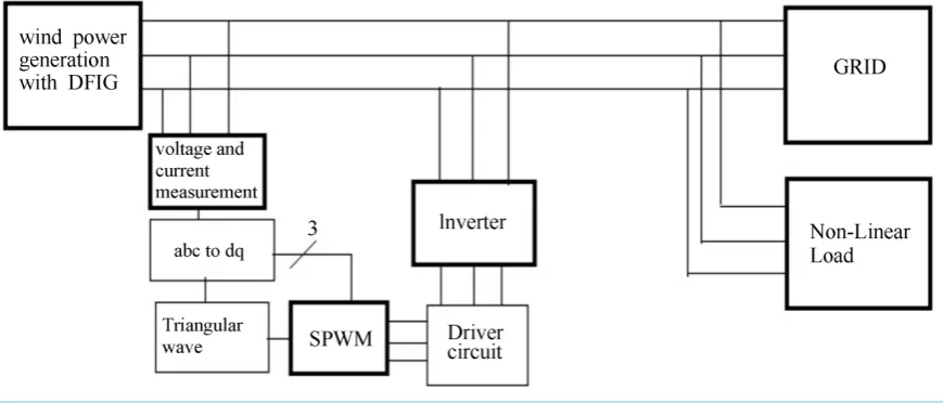
The more usual active power filter (APF) configuration is connected in shunt at the point of common coupling to inject the current harmonics. To cancel the harmonics and compensate the reactive power, an active power filter is the suitable solution [8]. The APF concept uses an inverter to inject currents or voltage harmonic com-ponents to cancel the load harmonic comcom-ponents; it is also called as Active Power Line Conditioners (APLC). This filter can be installed in a low voltage power system to compensate one or more loads. Thus, it avoids the transmission of current harmonics in the system [9]. The enhancements of different control strategies give APF to a new location. Gyugyi and Strycula first introduced the concept of shunt APLC in 1976. Figure 1 shows the overall block diagram of wind energy system connected to the grid and non-linear load along with APF.
The voltage source inverter should be controlled in such a way as to generate the voltages, which are same as the reference voltages generated, by the detection and control block. Here in this work, sinusoidal pulse width modulation (SPWM) is used as the switching strategy for the inverter. Actually, any PWM technique can be used as the switching strategy for the VSI.
3. Sine Pulse Width Modulation
Actually, any PWM technique can be used as the switching strategy for the VSI. However, due to constant switching frequency, the SPWM technique has been chosen to control the VSI. The following reasons will jus-tify the selection of SPWM as the control strategy for the VSI.
Figure 1. Wind power generation with shunt active filter.
2) From the theory of SPWM [9], we know that the fundamental of the output of the inverter will be same as the modulating waveform used to compare the triangular carrier.
Combining (1) and (2) it can be concluded that if the reference voltages generated by the detection and con-trol block are given as the modulating waveforms for the inverter then the fundamental component of the output of the inverter will be same as the reference voltages generated by the detection and control block [10]. This in-herent advantage of SPWM (which makes the design much simpler) justifies the selection of SPWM as the switching strategy for the inverter. Along with this, the SPWM technique also has advantage of very high mod-ulation frequency, which in turn reduces the filter requirement [8].
The switches in the voltage source inverter can be turned on and off as required. In the simplest approach, the top switch is turned on and off only once in each cycle, resulting in a square wave waveform. However, if turned on several times in a cycle an improved harmonic profile may be achieved.
In the most straightforward implementation, generation of the desired output voltage is achieved by compar-ing the desired reference waveform (modulatcompar-ing signal) with a high-frequency triangular “carrier” wave, as de-picted schematically in Figure 2. Depending on whether the signal voltage is larger or smaller than the carrier waveform, either the positive or the negative DC bus voltage is applied at the output. Note that over the period of one triangle wave, the average voltage applied to the load is proportional to the amplitude of the signal (as-sumed constant) during this period [11].
The resulting chopped square waveform contains a model of the desired waveform in its low frequency com-ponents, with the higher frequency components being at frequencies close to the carrier frequency.
The root mean square value of the AC voltage waveform is still equal to the DC bus voltage, and hence the PWM process does not affect the total harmonic distortion. The harmonic components are merely shifted into the high frequency range and are automatically filtered due to inductances in the AC system.
When the modulating signal is a sinusoid of amplitude Am, and the amplitude of the triangular carrier is Ac, the ratio m = Am/Ac is known as the modulation index. The modulation index controls the amplitude of the ap-plied output voltage [12]. With a sufficiently high carrier frequency (drawn for fc/fm = 21 and t = L/R = T/3; T = period of fundamental), the high frequency components do not propagate significantly in the ac network (or load) due the presence of the inductive elements. However, a higher carrier frequency does result in a larger number of switching per cycle and hence in an increased power loss. Typically switching frequencies in the 2 - 15 kHz range is considered adequate for power systems applications. Figure 2 shows the principle of pulse width mod-ulation generated by SPWM technique. In this control technique, the triangular wave is compared to desired waveform and pulse is generated accordingly.
Figure 2. Principle of pulse width modulation technique.
4. Simulation Analysis
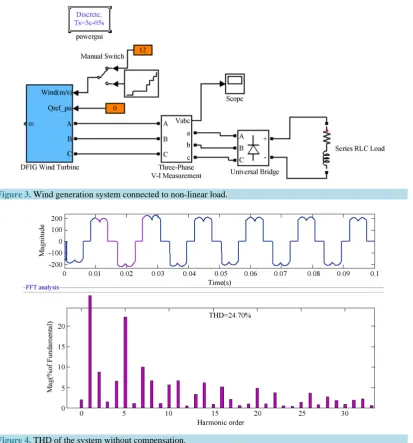
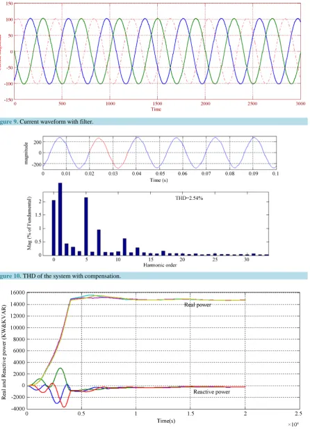
The simulation model of wind energy generation system with the DFIG is shown in Figure 3. This is con-structed in the MATLAB/SIMULINK environment with the variable wind speed and connected to non-linear load. Due to variation of speed, the output will be more distorted as shown in Figure 4. The total harmonic dis-tortion (THD) is measured with FFT analysis in matlab and is noted as 24.70%. This disdis-tortion level exceeds the harmonics standard IEEE 519-1992. Figure 5 illustrates the real and reactive power generated by the wind energy system connected to the grid. The reactive power is oscillatory for wind-generated system. The SAF connected to the system will compensate the both the harmonic distortion and reactive power oscillation.
To mitigate the distortions created by the non-linear load, the shunt active filter is used for compensation. The shunt active filter in turn controlled by the SPWM control scheme. This control scheme is used as the switching strategy for the inverter. Figure 6 shows the voltage and current in a-b-c coordinates tapped from the point of common coupling (PCC). Then a-b-c to d-q-o transformation is done. The d-q-o transform is often referred to as Park’s transformation. In the case of balanced three-phase circuits, application of the d-q-o transform reduces the three AC quantities to two DC quantities. Simplified calculations can then be carried out on these DC quan-tities before performing the inverse transform to recover the actual three-phase AC results. It is often used in order to simplify calculations for the control of three-phase inverters. After simplifying to d-q coordinate, the SPWM controller generates compensating pulse as shown in Figure 7. These pulses control the inverter accord-ing to the distortion created in the line. Then the inverter output signal is fed back into line. By this way, the distorted waveform is compensated.
After connecting the shunt active filter to the line, the distortion is reduced, as shown in Figure 8 & Figure 9.
Figure 3. Wind generation system connected to non-linear load.
Figure 4.THD of the system without compensation.
Figure 6.Wind generation system with compensation.
[image:6.595.100.538.148.676.2]Figure 7.Inverter pulse from SPWM.
Figure 8.Voltage waveform with filter.
Figure 9.Current waveform with filter.
[image:7.595.94.537.465.703.2]Figure 10. THD of the system with compensation.
By connecting the SAF, the quality of power to the grid and the non-linear load is considerably increased. The shunt active filter has the capability to compensate the harmonic distortion and keep it within the prescribed standard limit. With the help of the SPWM technique, the switching losses are reduced, utilization of DC power supply to deliver a higher output voltage is higher, good linearity in voltage and current control is achieved,
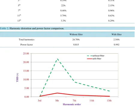
Table 1.THD based on harmonic order.
Harmonic order Before compensation After compensation
3rd 0.19% 0.31%
5th 22% 2.15%
7th 8.46% 0.96%
11th 5.79% 0.63%
[image:8.595.88.539.348.706.2]13th 3.3% 0.29%
Table 2.Harmonic distortion and power factor comparison.
Without filter With filter
Total harmonics 24.70% 2.54%
Power factor 0.815 0.992
reduces harmonic contents in the output voltage and current, especially in the low-frequency region. From the results, it is shown that the THD level with SAF is reduced to 2.54% from its original value 24.70%. Also, a near unity power factor is achieved in this case.
References
[1] Gawain, L., Tiwari, H. and Bansal, R.C. (2013) Improving Power Quality of Wind Energy Conversion System with Unconventional Power Electronic Interface. International Journal of Electrical Power & Energy Systems, 44, 445-453. http://dx.doi.org/10.1016/j.ijepes.2012.07.051
[2] Kesraoui, M., Chaib, A., Meziane, A. and Boulezaz, A. (2014) Using a DFIG Based Wind Turbine for Grid Current Harmonics Filtering. Energy Conversion and Management, 78, 968-975.
http://dx.doi.org/10.1016/j.enconman.2013.07.090
[3] Hoseinpour, A., Barakati, S.M. and Ghazi, R. (2012) Harmonic Reduction in Wind Turbine Generators Using a Shunt Active Filter Based on the Proposed Modulation Technique. International Journal of Electrical Power & Energy Sys-tems, 43, 1401-1412. http://dx.doi.org/10.1016/j.ijepes.2012.06.052
[4] Gaillard, A., Poure, P., Saadate, S. and Machmoum, M. (2009) Variable Speed DFIG Wind Energy System for Power Generation and Harmonic Current Mitigation. Renewable Energy, 34, 1545-1553.
http://dx.doi.org/10.1016/j.renene.2008.11.002
[5] Nian, H., Quan, Y. and Hu, J. (2012) Improved Control Strategy of DFIG-Based Wind Power Generation Systems Connected to a Harmonically Polluted Network. Electric Power Systems Research, 86, 84-97.
http://dx.doi.org/10.1016/j.epsr.2011.12.006
[6] Kesraoui, M., Chaib, A., Meziane, A. and Boulezaz, A. (2014) Using a DFIG Based Wind Turbine for Grid Current Harmonics Filtering. Energy Conversion and Management, 78, 968-975.
http://dx.doi.org/10.1016/j.enconman.2013.07.090
[7] Zeng, Z., Yang, H., Zhao, R. and Cheng, C. (2013) Topologies and Control Strategies of Multi-Functional Grid- Connected Inverters for Power Quality Enhancement: A Comprehensive Review. Renewable and Sustainable Energy Reviews, 24, 223-270. http://dx.doi.org/10.1016/j.rser.2013.03.033
[8] Melício, R., Mendes, V.M.F. and Catalão, J.P.S. (2011) Comparative Study of Power Converter Topologies and Con-trol Strategies for the Harmonic Performance of Variable-Speed Wind Turbine Generator Systems. Energy, 36, 520- 529. http://dx.doi.org/10.1016/j.energy.2010.10.012
[9] Anju, R.K. and Chacko, F.M. (2015). An Active Power Filter for Improving the Power Quality of a Distribution Grid.
International Journal of Engineering Research and General Science, 3, 875-882.
[10] Islam, M.S., Raju, N.I. and Ahmed, A.U. (2013) Sinusoidal PWM Signal Generation Technique for Three-Phase Vol-tage Source Inverter with Analog Circuit & Simulation of PWM Inverter for Standalone Load & Micro-Grid System.
International Journal of Renewable Energy Research (IJRER), 3, 647-658.
[11] Raju, N.I., Islam, M.S., Ali, T. and Karim, S.A. (2013) Study of SPWM Technique & Simulation of Designed Analog Circuit (Op-Amp) Controlled Three-Phase PWM Inverter with Harmonic Reduction. International Conference on In-formatics, Electronics & Vision (ICIEV), Dhaka, 17-18 May 2013, 1-6.
[12] Chelladurai, J., Ilango, G.S., Nagamani, C. and Kumar, S.S. (2008) Investigation of Various PWM Techniques for Shunt Active Filter. International Journal of Electrical Systems Science and Engineering, 1, 87-93.
[13] Singh, N. and Agarwal, V. (2015) A New Random SPWM Technique for AC-AC Converter-Based WECS. Journal of