GENETIC-FIREFLY ALGORITHM TO CONTROL LOAD
FLOW OF POWER SYSTEM BY OPTIMAL LOCATION AND
CAPACITY OF UPFC
1G.GOKULAKRISHNAN, 2DR.V. RAMESH
1
Assistant Professor, School of Electrical Engineering (SELECT), VIT University, Vellore, Tamilnadu
2Professor, School of Electrical Engineering (SELECT), VIT University,
Vellore, Tamilnadu
E-mail: [email protected]
ABSTRACT
An improved firefly algorithm is investigated with the aid of genetic algorithm (GA). The proposed algorithm improves the load ability of power system with unified power flow controller (UPFC). Random movement factor of firefly algorithm is improved by hybridizing the GA with classical firefly algorithm. In firefly algorithm, the next movement of firefly is depends on the movement factor which is determined by randomly so the best movement of firefly is possibility to fails by the distribution of random number. Thus, the best location of and capacity of UPFC can never able to recognize accurately. So in this paper, a GA based optimization algorithm is used to determine the optimal random movement factor of fireflies. Thus, the optimal location and capacity of UPFC is determined efficiently when compared to traditional fire fly algorithm. The proposed method implemented in MATALB and the optimal location and capacity of UPFC is examined as per the variation of voltage, power loss and power balance of the network. The load power control performance of proposed method is compared with classical firefly algorithm.
Keywords: Improved Firefly, GA, Load Ability, UPFC, Location, Capacity, And Load Variation.
1. INTRODUCTION
All round the world, due to the environmental and economic controls to erect novel generating plants and transmission lines, Electric power systems have been compelled to function to more or less their full capacities [2] [3]. By security and constancy controls, the amount of electric power that can be broadcasted between two positions through a transmission network is restricted [1]. Power flow in the lines and transformers should not be permitted to raise to a level where a random event could cause the network collapse as flowed outages [4] [5]. The system is said to be obstructed when such a limit accomplishes. Managing obstruction to diminish the constraints of the transmission network in the aggressive market has, consequently, turn into the central activity of systems operators [6]. It has been examined that the disappointing management of operations could raise the obstruction cost which is an unnecessary burden on customers [7].
For controlling the power transmission system, Flexible Alternating Current Transmission System
(FACTS) is a fixed apparatus applied [8] [9]. FACTS is described as "a power electronic based system and other fixed apparatus that offer control of one or more AC transmission system parameters to improve controllability and raise power transfer capability” [10]. The different kinds of FACTS tools obtainable for this purpose comprises Static Var Compensator (SVC), Thyristor controlled series Capacitor (TCSC), Static Synchronous series compensator (SSSC), Static Synchronous Compensator (STATCOM), Unified Power Flow Controller (UPFC) and Interlink Power Flow Controller (IPFC) [12]. By inserting dynamic and reactive voltage component in series with the transmission line, UPFC is one of the FACTS tools that can manage the power flow in transmission line among them [11] [13].
never be enhanced, has been monitored [16]. The optimal location and optimal capacity of a specified number of FACTS in a power system is a problem of combinatorial study [18] [19]. Dissimilar kinds of optimization algorithm have been applied such as genetic algorithms, simulated annealing, tabu search and etc to work out this kind of problem [17] [20]. In the document, the GA base enhanced firefly algorithm is suggested for controlling the load deviation of power system by computing the optimal location and sizing of UPFC. The GA is employed and the movement factor is optimized as a substitute of random movement factor of firefly. The specified report of suggested algorithm is offered in section 3. The current research works are explained in section 2 before that. The conversation of results and ending of document is offered in section 4 and 5 correspondingly.
2. RECENT RESEARCH WORK: A BRIEF REVIEW
In literature, numbers of related works are available which based on improving the power transfer capability of power system. Some of them reviewed here. For improving the security of power systems under single line contingencies, the efficiency of the optimal location of UPFC has been explored by H.I. Shaheen et al. [21]. Based on the emergency selection and ranking process, determinations of the severest emergency scenarios were executed. One of the latest computational intelligence methods, namely: DE has been effectively employed to the problem under deliberation. Maximization of power system security was regarded as the optimization principle. The presentation of DE was compared with that of GA and PSO. Moreover, they were carried out two case studies by means of an IEEE 14-bus system and an IEEE 30-bus system.
A strategy based on differential evolution method to find out the optimal position and parameter setting of UPFC for improving power system security under single line contingencies has been offered by Husam I. Shaheen et al. [22]. Initially, they carry out a contingency study and ranking process to find out the most severe line outage contingencies regarding line overloads and bus voltage limit violations as a presentation index. Secondly, they employ differential evolution method to determine the optimal location and parameter setting of UPFC under the determined emergency scenarios. They execute simulations on an IEEE 14-bus and an IEEE 30-bus power
systems. They acquired results point out that installing UPFC in the location optimized by DE could considerably improved the security of power system by removing or minimizing the overloaded lines and the bus voltage limit violations.
Lashkar Ara et al. [29] have improved suitable models of flexible ac transmission systems (FACTS) shunt-series controllers for multiobjective optimization and furthermore offered a multiobjective optimization methodology to locate the optimal location of FACTS shunt series controllers. The intent functions were thetotal fuel cost, power losses, and system loadability with and without minimum cost of FACTS installation. The
ε-constraint strategy was executed for the
multiobjective mathematical programming (MMP) formulation, together with the FACTS shunt series controllers. For the IEEE 14-bus system, Simulation results were offered.
To find optimal location of UPFC to accomplish optimal power flow (OPF), the application of hybrid immune algorithm (HIA) such as immune genetic algorithm (IGA) and immune particle swarm algorithm (IPSO) has been offered by Seyed Abbas Taher et al. [30]. The overall cost function, the objective function in the OPF, comprises the total active and reactive production cost function of the generators and installation cost of UPFCs and therefore, should minimized. The OPF controls are generators, transmission lines and UPFCs limits. It may not all the time be feasible to send out the contracted power transactions totally in power system due to congestion of the consequent transmission corridors. The simulations were executed on IEEE 14-bus and IEEE 30-bus test systems for dissimilar techniques.
In large power systems, a graphical user interface (GUI) based on a genetic algorithm (GA) has been offered by Ghahremani, E. et al. [32] which was shown able to locate the optimal locations and sizing parameters of multi-type FACTS tools. This user friendly tool, called the FACTS Placement Toolbox, permits the user to pick a power system network, find out the GA settings and choose the number and kinds of FACTS tools distributed in the network. To get optimal locations, the GA-based optimization process was used and ratings of the chosen FACTS to maximize the system static loadability. Five dissimilar FACTS devices were executed: SVC, TCSC, TCVR, TCPST and UPFC.
Using particle swarm optimisation (PSO) technique, to improve the power system loadability with optimal placement of flexible AC transmission system (FACTS) controllers, multi objective–based method has been proposed by Made Wartana et al. [33]. The intent function was maximized the system loadability subjected to upholding the system security, integrity, and stability margins inside limits by attaining the optimal location, installation costs, and control settings of the FACTS controllers. The diverse FACTS controllers, i.e., static var compensator (SVC), thyristor controlled series compensator (TCSC), and unified power flow controller (UPFC), have been regarded.
3. PROBLEM FORMULATION
UPFC power flow model
UPFC is one of the FACTS tools which competent to presenting true and reactive power flow control among its terminals [23]. The reactive power is reimbursed when attached UPFC. With one dc link capacitor, the series and shunt converters are attached. The inserting transformer applied to give the link of the converters and power transmission line. The UPFC is controlling the power flow among transmission lines by inserting the true and reactive power. The power flow injection copy and the corresponding circuit model of UPFC among transmission line x and y are specified in Fig.1. The functioning of UPFC can know simply from the power flow and corresponding circuit model.
(i)
(ii)
Fig1: (I And Ii): Power Flow Model And Equivalent Circuit Of UPFC.
The DC link is assisted to balance the real power among the two voltage source converters so the real power loss is ignored. On the other hand, the voltage converters can produce or soak up the reactive power. To acquire the stable state system model, the above UPFC equivalent circuit model is applied. In the UPFC circuit copy, the two ideal voltage sources of UPFC signifying the fundamental Fourier series factor of the switched voltage waveforms at the AC converter terminals [24]. From the load flow studies technique, the power flow model of series and shunt converters are obtained [25]. The power flow of UPFC is computed according to the follow equation. The equation (1) and (2) are signify the true and reactive power injected to series and shunt converter.
(
)
(
)
(
)
(
)
(
)
(
yy injse y yy injse y)
y se inj
x se inj xy x se inj xy
x sh inj yy se inj se inj
B G
V V
B G
V V G V P
θ θ θ
θ
θ θ θ
θ
− +
− +
− +
− + =
, ,
,
, ,
, 2
, ,
sin cos
sin cos
(
)
(
)
(
)
(
)
(
)
(
yy injse y yy injse y)
y se inj x se inj xy x se inj xy x se inj yy se inj se injB
G
V
V
B
G
V
V
G
V
Q
θ
θ
θ
θ
θ
θ
θ
θ
−
−
−
+
−
−
−
+
−
=
, , , , , , 2 , ,cos
sin
cos
sin
(2)(
)
(
)
(
injsh injsh x injsh injsh x)
x sh inj sh inj sh inj sh inj B G V V G V P θ θ θθ − + −
+ − = , , , , , , 2 , , sin cos (3)
(
)
(
)
(
injsh injsh x injsh injsh x)
x sh inj sh inj sh inj sh inj
B
G
V
V
G
V
Q
θ
θ
θ
θ
−
−
−
+
=
, , , , , , 2 , ,cos
sin
(4)Where,
P
inj,se,Q
inj,se,P
inj,sh, andQ
inj,share thereal and reactive power injected to series and shunt
converter.
G
yy,G
inj,sh, andG
xyare the real part ofthe element of the admittance matrix of buses
y
x,
and shunt converter respectively.B
yy,sh inj
B
, , andB
xyare the imaginary part of theelement of the admittance matrix of buses
x,
y
andshunt converter respectively.
V
inj,sh,V
inj,se,V
x,and
V
yare the magnitude of injected voltage ofseries, shunt converter, and magnitude of bus
voltage
x
andy
.θ
inj,se,θ
inj,sh,θ
x, andθ
yare injected angle of series, shunt converter, and voltage angle of bus voltagex
andy
. Then, the constraints of voltage instability problem is described as following them,Equality constraints:
The power flow equations are regarded as sameness constraints for upholding the load ability of power system by means of UPFC. The power flow equation of buses x and y are rely on the demand, voltage magnitude, and angle correspondingly. Moreover, the power balance condition is regarded as another equality constraint which explained in equation (9). The power balance equation depends on the generator power, demand, and loss of the whole system. The regarded power flow equation is set as following them,
At bus x:
dx x
gx
P
V
P
P
=
(
,
θ
)
+
(5)dx x
gx
Q
V
Q
Q
=
(
,
θ
)
+
(6) At bus y:dy y
gy
P
V
P
P
=
(
,
θ
)
+
(7)dy y
gy
Q
V
Q
Q
=
(
,
θ
)
+
(8)∑
∑
= =+
=
G g N i loss Li N igi
P
P
i
P
1 1
)
(
(9)Where,
P
gx,Q
gx,P
gy, andQ
gyare the real andreactive power of generator to bus x and y.
)
,
(
V
θ
P
x ,Q
x(
V
,
θ
)
,P
y(
V
,
θ
)
, and)
,
(
V
θ
Q
y are the real, reactive power, voltagemagnitude, and angle of bus x and y.
P
dx,Q
dx,dy
P
, andQ
dyare the real and reactive powerdemand of bus x and y.
P
giis the real power ofth
i
generator,P
Liis the real power ofi
th load bus andP
loss(i
)
is the power loss ofi
th bus.Inequality constraints
The inequalities constraints are defined which parameters are depending on the stability of the system and the limits are selected as inequality constraints. Usually, the real
P
gi, reactivegi
Q
power of generator, voltage magnitudeV
i, andangle
θ
iare selected as the inequality constraints. In the case of stability by UPFC is depending on the injected voltage magnitude and angle of shunt and series active converter respectively. The maximum and minimum limits of the inequality constraints are represented as following them,g gi
gi
gi
P
P
i
n
P
min≤
≤
max=
1
,
2
,...
(10)g gi
gi
gi
Q
Q
i
n
Q
min≤
≤
max=
1
,
2
,...
(11)g i
i
i
V
V
i
n
V
min≤
≤
max=
1
,
2
,...
(12)max min
i i
i
θ
θ
θ
≤
≤
(13) max, ,
min
,sh injsh injsh
inj
V
V
V
≤
≤
(14) max, ,
min
,sh injsh injsh
inj
θ
θ
θ
≤
≤
(15) max, ,
min
,se injse injse
inj
V
V
V
≤
≤
(16) max, ,
min
,se injse injse
inj
θ
θ
the optimization algorithm is used to determine the optimal location and capacity of UPFC. To perform the optimization algorithm, the parameters are optimized to decide the power flow of the system. In the paper, the GA based firefly algorithm is proposed to perform the optimization process. The following parameters are considered in the optimization process:
(i) The optimal location of UPFC in the network is considered as the first step of optimization process. Here, the network variables such as voltage changes, power loss and system balance condition are incorporate with the optimization algorithm.
(ii) Then, the capacity of UPFC is determined according to the working range of network.
For that, the series and shunt voltage source converter injected voltage ranges are determined. (iii) From that, the real and reactive power flow model of UPFC is examined. Also the stability of the system is evaluated. These are the steps used to analyze the stability and control the power flow of the system.
3.2. Proposed GA based Firefly Algorithm
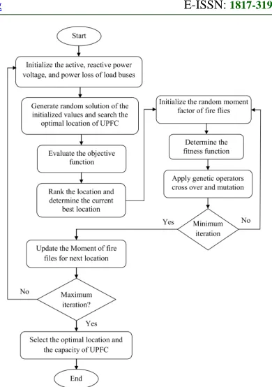
[image:5.612.322.517.78.355.2]Firefly Algorithm is one of the optimization algorithm which progressed based on the blinking performance of fireflies [26]. In the document, an enhanced fire fly algorithm is suggested to develop the load ability of power system. The firefly algorithm is enhanced by hybridize the GA with classical algorithm to verified the random movement factor. In firefly algorithm, the subsequent movement of firefly is depends on the progress factor. But the movement factor is determined by arbitrarily so the most excellent movement of firefly is possibility to miss by the sharing of random number. Therefore, the top position of and capacity of UPFC is can never able to recognized precisely. Hence, a GA based optimization algorithm is suggested to find out the optimal random movement factor of fireflies in this paper. Therefore, when compared to traditional fire fly algorithm, the optimal location and capacity of UPFC is found out competently. According to the suggested fire fly algorithm, the optimal location and capacity of UPFC is found out. Now, the position of UPFC is determined as per the deviation of voltage, power loss and power balance of the network. The ability of UPFC is found out as per the real power of the load buses. The flowchart of suggested algorithm is explained as following them,
Fig 2: Flow Chart For Proposed Technique.
According to the searching concept of traditional firefly algorithm, the proposed algorithm is improved. The steps of the proposed improve firefly algorithm can be summarized as the following them,
Steps of GA based firefly algorithm
Step 1: First the network dates are
initialized. Here, the voltage, real and reactive power of the load bus of the power system is initialized. The initialized system parameters
considered as a function which denoted as
f
( x
)
. Also, the algorithm parameters are predeterminedsuch as maximum attractiveness
β
0 , absorption coefficientγ
, initial distance of firefliesd
jand random factorα
nrespectively.Step 2: From the initialized values, the random number of solution is generated. To control the system when load varies, the UPFC location is determined as per the power loss and voltage
deviation of load bus. So the
f
( x
)
is to be varied according to the number of optimal variable. For]
,
,....
,
[
)
(
x
x
1x
2x
n 1x
nf
=
− (18)The
f
( x
)
is depends on the power loss of the system which depends on the constraints that is denoted asJ
. The location of UPFC is depends on which load bus affect high power loss while the real power is varied. The output function is described as follow,)
max(
)
(
x
outputx
nf
=
(19)Step 3: Start the iteration count and determine the optimal location of UPFC. At the end of iteration, ranking the solution by using equation (19) and determine the current best solution as per the rank.
Step 4: In this step, the optimal random movement factor is optimized by GA. Initialize, the
random movement factor
α
n(
0
,
1
)
for counting the iteration level. The range of random movement factor is described as follow,max , min
, n n
n
α
α
α
≤
≤
(20)From the initialized random movement factor, the fitness is evaluated. The fitness depends on the distance updating formula of the fireflies. Apply genetic operators [27] cross over, mutation and selection. The best selection i.e. optimal random movement factor depends on the distance of the fireflies. If the distance is low select minimum level random factor
α
n,min. If the distance of the firefliesis high select maximum level random factor
α
n,max. According to the optimal output) (optimal
n
α
of GA, the next location of fireflies is rearranged.Step 5: The location of fireflies rearranged by equation (21) and the equation is represented as follow,
(
)
koptimal n k n k m d k
n k
n
x
e
x
x
x
j) ( 0
1
=
+
β
−γ−
+
α
+ (21)
Where,
α
nk(optimal)is the optimal randommovement factor.
Step 6: Check the optimal location of UPFC is at the end of the maximum iteration. If, it not reaches the optimal location go to step 3 and increase the iteration.
Then, the capacity of UPFC is determined as per the voltage level of magnitude and angle of load buses. According to this approaches, the steps to determine the optimal location and capacity of
UPFC by proposed firefly approach can be summarized as the pseudo code which described as follow,
Pseudo code of proposed firefly algorithm to determined the optimal location and capacity of UPFC
Input:
]
,
,....
,
[
)
(
x
x
1x
2x
n 1x
nf
=
−{location of UPFC} Output:
)
max(
)
(
x
outputx
nf
=
{optimal location of UPFC}begin for n=1 to t
x
n←
generate load bus voltages as initial solution endrepeat
n
min←
arg
min
nf
(
x
n)
x
nmin←
arg
min
xnf
(
x
n)
for n=1 to t do for m=1 to t do
if
f
(
x
m)
<
f
(
x
n)
then {move firefly n towards m}
α
n←
optimize the random movement factor by GAfor k=1 to n do
(
)
koptimal n k n k m d k
n k
n
x
e
x
x
x
j) ( 0
1
=
+
β
−γ−
+
α
+
end end end end
α
nk(optimal)←
(
min
α
n,
max
α
n)
until stop condition trueend
4. RESULTS AND DISCUSSION
compared with traditional firefly algorithm and the outcomes are analyzed.
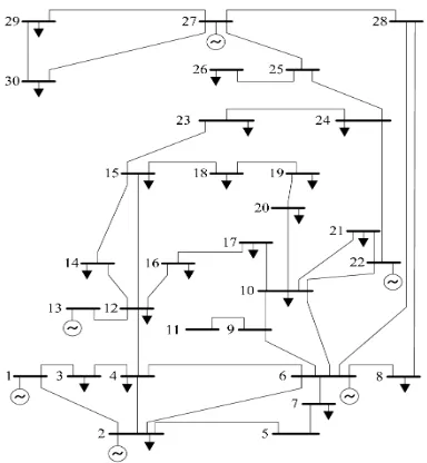
Fig 3: Structure Of IEEE 30 Bus Bench Mark System.
From the testing bus system, the load bus details active power, voltage magnitude, and angle are defined. Then, the load power of load bus is varied arbitrary from the actual value. Initialize the load variation in the proposed method. By the initialized
values, the optimal location and capacity of UPFC is determined. Then, the UPFC is located between two buses and the active load variation controllability performance is examined. Also, the magnitude of load voltage and the system power loss are evaluated by proposed firefly algorithm and classical algorithm. The normal load power, during load variation and the load power after connecting UPFC by proposed method and classical firefly algorithm are examined. The examined load power data’s are tabulated as in table I.
[image:7.612.95.521.437.718.2]In table I, the load power is examined while normal load, load variation, and after connecting UPFC. The optimal location and capacity of UPFC is determined by two methods. One is proposed method and another firefly algorithm. As per the optimal location, the UPFC is installed between from and to load buses which are listed in the corresponding table I. During load variation, the normal load of the system is deviated from the actual load condition. So, the load ability of the corresponding load buses is affected. To control the load variation, proposed method uses incorporation of UPFC. The comparison chart of load power of buses is presented in Fig 4 and 5.
Table I: Load Bus Power: Normal Load, Load Variation, And After Connecting UPFC.
Load buses Normal load in MW
Load variation power in MW
After connecting UPFC load power in MW
From bus
To bus
Firefly algorithm Proposed method
10 22 5.80 0 10.7700 4.9700 2.1907 4.8729 0.8997 4.2047 22 24 0 8.70 4.890 13.590 3.61 8.7000 1.8424 7.4566 9 10 0 5.800 4.950 10.750 1.8972 5.0258 2.6857 4.277 23 24 3.20 8.70 8.180 13.680 5.3268 2.3658 5.2163 2.2941 12 13 11.2 0 16.15 4.950 14.6271 1.7371 7.7912 3.2094 16 17 3.500 9.000 8.440 13.940 3.500 9.0000 2.3215 4.9066 7 8 22.8 30.00 27.56 34.76 18.9804 25.9534 18.1447 25.4364 15 16 8.20 3.50 13.04 8.3400 4.9991 0.2516 4.1828 0.0920
3 4 2.40 7.60 7.350 12.550 0.2645 5.7929 0.9161 5.2568 29 30 2.40 10.60 7.300 15.500 3.5294 6.0373 1.2759 8.2328 19 20 9.500 2.200 14.450 7.1500 2.6403 6.7724 7.2457 0.6370
From fig.4 and 5, the load ability performance of proposed method is analyzed with actual load of the system and during load variation. When load varied suddenly, it changed from the actual value so the stability of the system gets affected. Here, firefly and proposed algorithm working towards maintain the stability of the system by connecting UPFC. The UPFC is injecting the power both connected buses and the load flow power is balanced. When evaluate the balance power, the proposed method control the load power variation effectively compared to firefly algorithm. Hence the stability of the system towards maintains the normal system.
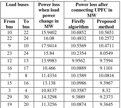
[image:8.612.317.524.73.209.2]The power loss of the system is analyzed while normal load, load variation, and after connecting UPFC. As per the optimal location, the UPFC is installed between from and to load buses and the power loss are illustrated in table II. For the duration of load variation, the power loss of the system is deviated from the actual system power loss i.e. 10.805 MW. When power loss increased, the load buses are affected because of insufficient power to balance the load. Therefore, the load ability of the consequent load buses is to be exaggerated. After connecting UPFC, the power loss of the system gets reduced. The power loss comparison chart of load buses is presented in Fig 6.
Table II: Power Loss Of System: Normal Load, Load Variation, And After Connecting UPFC.
Load buses Power loss when load power change in
MW
Power loss after connecting UPFC in
MW From
bus To bus
Firefly algorithm
Proposed method
10 22 15.9402 10.6852 10.5651 22 24 16.08 10.4832 10.2572 9 10 17.9414 10.5569 10.4711 23 24 15.84 10.2354 8.0549 12 13 13.9983 9.9562 9.7594 16 17 10.466 10.0889 9.1101 7 8 11.4334 10.1589 10.0816 15 16 13.138 10.0986 9.3967
[image:8.612.93.297.446.627.2]3 4 10.8137 10.3587 8.32 29 30 14.3298 9.3889 9.2373 19 20 11.3256 10.0874 9.3645
Fig 6: Power Loss Comparison Chart Of Varied Load, UPFC With Firefly And UPFC With Proposed Method.
In fig.6, the power loss of the system is compared with firefly algorithm and proposed method. The comparison is examined with the power loss of system load at abnormal condition. The examination is evaluated with 11 different loading levels. When load changed, the power loss of the system is increased maximum level as 17.9414 MW. But, the power loss of the system is reduced as 9.3889 MW by UPFC with firefly algorithm. However, the proposed method with UPFC is reducing the power loss as 8.0549 MW. This power loss is the minimum power loss among all the loading levels. As per the comparison, the proposed method gives as less power loss to compare with firefly algorithm.
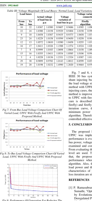
Table III: Voltage Magnitude Of Load Buses: Normal Load, Load Variation, And After Connecting UPFC.
Load buses
Actual voltage of load bus in
p.u
Voltage variation of load bus in p.u
Voltage variation of load bus after connecting UPFC in p.u
From bus
To bus
Firefly algorithm
Proposed method
10 22 1.0367 1.0300 0.9607 0.9686 1.0385 1.0900 1.0224 1.0100 22 24 1.0300 1.0158 0.9529 0.9404 1.0158 0.9991 1.0100 0.9991 9 10 1.0458 1.0367 0.9435 0.9373 1.0658 1.0315 1.0270 1.0217 23 24 1.0229 1.0158 0.9599 0.9650 1.0258 0.9913 0.9990 1.008 12 13 1.0572 1.0610 1.0380 1.0458 1.0255 1.0310 1.0198 1.0210 16 17 1.0411 1.0326 1.1588 1.1574 1.0324 1.0203 1.0300 1.0242 7 8 0.9999 1.0103 1.0698 1.0864 1.0158 1.0096 0.9983 1.0091 15 16 1.0355 1.0411 1.0534 1.0585 1.0106 0.9940 1.0217 1.0361 3 4 1.0228 1.0136 1.2331 1.2324 1.0387 1.0136 1.0192 1.0108 29 30 0.9899 0.9782 1.0143 1.0012 0.8599 0.8537 0.9583 0.9453 19 20 1.0198 1.0232 1.4990 1.2020 0.9664 0.9707 0.9939 0.9977
Fig 7: From Bus Load Voltage Comparison Chart Of Varied Load, UPFC With Firefly And UPFC With
Proposed Method.
Fig 8: To Bus Load Voltage Comparison Chart Of Varied Load, UPFC With Firefly And UPFC With Proposed
Method.
[image:9.612.90.389.64.712.2]
Fig 9: Performance Of Generation For Reducing The System Power Loss.
Fig. 7 and 8, the load voltage stability of the IEEE 30 bus system is evaluated for series and shunt injecting buses. From the examined results, the load voltage stability improvement of proposed method with UPFC is revealed. In shunt and series injecting cases, the voltage stability of the proposed method is improved as better level when compared to UPFC with firefly algorithm. Also, the iteration cure is described for proposed algorithm (GA-firefly) and firefly is illustrated in Fig 9. From the iteration curve, the proposed method gives up minimum power loss as compared with firefly algorithm. Therefore, the load power variation is controlled effectively by proposed method.
5. CONCLUSION
The proposed load power control method by UPFC was implemented in MATLAB and the performance is evaluated. The performance of load bus power, voltage magnitude, and power loss were examined and compared with classical algorithm. From evaluating the effectiveness, different loading level are used. The comparative analysis shows that, the proposed method give better control performance when compared to classical firefly algorithm. Also, the comparison charts of control load power and the power loss are analyzed. The characteristics of power loss, voltage, and power loss iteration are studied.
REFERENCES
[1] P. Ramasubramanian, G. Uma Prasana, and K. Sumathi, "Optimal Location of FACTS Devices by Evolutionary Programming Based OPF in Deregulated Power Systems", British Journal of
Mathematics & Computer Science, Vol.2, No.1,
[2] Rakhmad Syafutra Lubis, Sasongko Pramono Hadi, and Tumiran, "Selection of Suitable Location of the FACTS Devices for Optimal Power Flow", International Journal of Electrical & Computer Sciences, Vol.12, No.3,
pp.38-49, 2012
[3] S.Durairaj, and B.Fox, "Optimal Placement of Facts Devices", International Conference on
Energy & Environment, 2008
[4] D. Devaraj, and J. Preetha Roselyn, "Genetic algorithm based reactive power dispatch for voltage stability improvement", International
Journal of Electrical Power & Energy Systems,
Vol.32, No.10, pp.1151–1156, December 2010 [5] Chaohua Dai, Weirong Chen, Yunfang Zhu, and
Xuexia Zhang, "Reactive power dispatch considering voltage stability with seeker optimization algorithm", Electric Power Systems Research, Vol.79, No.10, pp.1462–
1471, October 2009
[6] A.H. Khazali, and M. Kalantar, "Optimal reactive power dispatch based on harmony search algorithm", International Journal of
Electrical Power & Energy Systems, Vol.33,
No.3, pp.684–692, March 2011
[7] Habibollah Raoufi, and Mohsen Kalantar, "Reactive power rescheduling with generator ranking for voltage stability improvement",
Energy Conversion and Management, Vol.50,
No.4, pp.1129–1135, April 2009
[8] Rahul J. Shimpi, Rajendra P. Desale, Kunal S. Patil, Jaswantsing L. Rajput and Shailesh B. Chavan, "Flexible AC Transmission Systems",
International Journal of Computer Applications, Vol.1, No.15, pp.54-57, 2010
[9] P. K. Dash, S. R. Samantaray, and Ganapati Panda, "Fault Classification and Section Identification of an Advanced Series-Compensated Transmission Line Using Support Vector Machine", IEEE Transaction on Power
Delivery, Vol.22, No.1, pp.67-73, January 2007
[10] H O Bansal, H P Agrawal, S Tiwana, A R Singal and L Shrivastava, "Optimal Location of FACT Devices to Control Reactive Power",
International Journal of Engineering Science and Technology, Vol.2, No.6, pp.1556-1560,
2010
[11] D. Murali, and M. Rajaram, "Active and Reactive Power Flow Control using FACTS Devices", International Journal of Computer
Applications, Vol.9, No.8, pp.45-50, 2010
[12] Xuan Wei, Joe H. Chow, Behruz Fardanesh and Abdel-Aty Edris, "A Common Modeling Framework of Voltage-Sourced Converters for
Load Flow, Sensitivity, and Dispatch Analysis",
IEEE Transactions On Power Systems, Vol.19,
No.2, pp.934-941, May 2004
[13] S. V. Ravi Kumar, and S. Siva Nagaraju, "Functionality of UPFC in Stability Improvement", International Journal of Electrical and Power Engineering, Vol.1, No.3,
pp.339-348, 2007
[14] Jigar S.Sarda, Vibha N.Parmar, Dhaval G.Patel, and Lalit K.Patel, "Genetic Algorithm Approach for Optimal location of FACTS devices to improve system loadability and minimization of losses", International Journal of Advanced
Research in Electrical, Electronics and Instrumentation Engineering, Vol.1, No.3,
pp.114-125, 2012
[15] Gerbex, S., Cherkaoui, R., and Germond, A.J., "Optimal location of FACTS devices to enhance power system security", IEEE Bologna Power
Tech Conference Proceedings, 2003
[16] Cai, L.J., Erlich, I., and Stamtsis, G., "Optimal choice and allocation of FACTS devices in deregulated electricity market using genetic algorithms", IEEE PES Power Systems Conference and Exposition, 2004
[17] Mori, H., and Goto, Y., "A parallel tabu search based method for determining optimal allocation of FACTS in power systems",
International Conference on Power System Technology, 2000
[18] Wang Feng, and Shrestha, G.B., "Allocation of TCSC devices to optimize total transmission capacity in a competitive power market", IEEE
Power Engineering Society Winter Meeting,
2001
[19] Vaidya, P.S., and Rajderkar, V.P., "Optimal Location of Series FACTS Devices for Enhancing Power System Security", 4th
International Conference on Emerging Trends in Engineering and Technology, 2011
[20] Mahdad, B., Bouktir, T., and Srairi, K., "GA Coordinated with Practical Fuzzy Rules with Multi Shunt FACTS Devices to Enhance the Optimal Power Flow", The International
Conference on Computer and Tool, 2007
[21] H.I. Shaheen, G.I. Rashed, S.J. Cheng, "Application and comparison of computational intelligence techniques for optimal location and parameter setting of UPFC", Engineering
Applications of Artificial Intelligence, Vol.23,
pp.203–216, 2010
security based on Differential Evolution algorithm", Electrical Power and Energy
Systems, Vol.33, pp.94–105, 2011
[23] Vasquez-Arnez, R.L, and Zanetta, L.C., "Compensation strategy of autotransformers and parallel lines performance, assisted by the UPFC", IEEE Transactions on Power Delivery, Vol.20, No.2, pp.1550-1557, April 2005 [24] Claudio A. Canizares, Edvina Uzunovic, and
John Reeve, "Transient stability and power flow model of the Unified Power Flow controller for various control strategies", International Journal of Energy Technology and Policy,
Vol.4, No.3, pp.349-378, 2006
[25] Fang W, and Ngan HW, “A robust load flow technique for use in power systems with unified power flow controllers”, Electric Power System
Research, Vol.53, pp.186-186, 2000
[26] Szymon Lukasik, and Slawomir Zak, "Firefly Algorithm for Continuous Constrained Optimization Tasks", Computational Collective
Intelligence: Semantic Web, Social Networks and Multiagent Systems, Vol.5796, pp.97-106,
2009
[27] Frenzel, J.F, "Genetic algorithms", IEEE
Potentials, Vol.12, No.3, pp.21-24, 1993
[28] The IEEE 30 bus system data referred from http://www.ee.washington.edu/research/pstca/. [29] Lashkar Ara, A., Kazemi, A., and Niaki,
S.A.N., “Multiobjective Optimal Location of FACTS Shunt-Series Controllers for Power System Operation Planning”, IEEE Transactions on Power Delivery, Vol.27, No.2,
pp.885-897, 2012
[30] Seyed Abbas Taher, and Muhammad Karim Amooshahi, "New approach for optimal UPFC placement using hybrid immune algorithm in electric power systems", International Journal
of Electrical Power & Energy Systems, Vol.43,
No.1, pp.899–909, 2012
[31] Ya-Chin Chang, "Multi-Objective Optimal SVC Installation for Power System Loading Margin Improvement", IEEE Transactions on
Power Systems, Vol.27, No.2, pp.885-895, 2012
[32] Ghahremani, E., and Kamwa, I., "Optimal Placement of Multiple-Type FACTS Devices to Maximize Power System Loadability Using a Generic Graphical User Interface", IEEE
Transactions on Power Systems, Vol.28, No.2,
pp.764-778, 2013
[33] Made Wartana, Jai Govind Singh, Weerakorn Ongsakul, Sasidharan Sreedharan, "Optimal placement of FACTS controllers for maximising system loadability by PSO",