2159
DYNAMICALLY EVOLVABLE HARDWARE-SOFTWARE
CO-DESIGN BASED CRYPTO SYSTEM THROUGH
PARTIAL RECONFIGURATION
1B.MURALI KRISHNA, 2G.L.MADHUMATI, 1*HABIBULLA KHAN
1
Research Scholar, 1*Professor & Dean Student Affairs, Department of ECE, K L University, AP, India;
2
Professor & H.O.D Department of ECE, Dhanekula Institute of Engineering & Technology, AP, India; E-mail: [email protected]
ABSTRACT
Cryptography establishes a secure channel for data communication between sender and receiver. Nowadays, millions of online transactions happen in seconds throughout the world like trading, banking, e-commerce, and social networking etc., exchanges data among users. Evolution in internet led to increase in number of hackers, cyber attacks over network, network security has become a major issue in present era data protection has become significant, such that an unbreakable encryption technology should be designed in order to provide security for the data. The advent of VLSI technology has grown enormously in the last two decades by extending its prominence towards network security where mainly information processing cryptography has gained popularity in this field. This paper presents a module in cryptosystem is partially reconfigurable (PR) in run time which serves two purposes. One module for dynamic key generation mechanisms and second module for inverse permutation block in Data Encryption Standard (DES) and shift rows block in Advanced Encryption Standard (AES) cryptography techniques which play a vital role in data security. A new approach with Deoxyribonucleic Acid(DNA)structure have four nucleotides which are named as A (Adenine), C (Cytosine), G (Guanine) and T (Thymine) are the elements existing in DNA mechanism is applied on both cipher and key are merged and transmitted along a channel in protein form which enhances the security. Run time evolvable hardware like, Field Programmable Gate Array (FPGA) architecture and its behavior changes dynamically with partial reconfiguration are suitable for wide variety of applications which can configure to implement custom designs and needs. Encryption Techniques are designed using Verilog HDL, synthesized in Xilinx simulated with ISIM simulator and implemented on Virtex FPGA architecture. Dynamic keys and reconfigurable modules are generated by loading Partial bit streams from CF Card are configured to FPGA by issuing commands in serial Terminal through MicroBlaze Processor.
Keywords: Cryptography, Partial Reconfiguration, AES, DES, DNA, FPGA.
1. INTRODUCTION
Cryptography mainly aims at maintaining data
integrity, non-repudiation, authenticity and
confidentiality. Network security gains more
significance to overcome cyber attacks from unauthorized access of confidential information. In order to provide high data there are two prominent and efficient methods. (a) Cryptography and (b) Steganography Cryptographyis an art of transferring information secretly over vulnerable channels. It is used for communicating through an untrusted network which can be understandable only by the admin. Steganography is an art of hiding the actual data using duplicate data [1]. There are handful numbers of algorithms for providing information security over communication channels. Security is the main factor for the transfer of information among several people using those algorithms [2].However; those algorithms
2160 Fig 1: Encryption and Decryption
In Cryptography, the encryption and decryption process should be on sync with each other based on public and private key mechanisms [4].
1.1 Symmetric Encryption Technique
[image:2.612.370.494.369.521.2]Symmetric Encryption Technique uses a common key i.e., known as pre shared private key between sender and receiver as an agreement. Sender encrypts the message with key produces a cipher which sends to receiver.
Fig 2: Symmetric Key for Encryption & Decryption.
Receiver performs several permutations on cipher along with key to decrypt the original text message. Same key is used to encode the message with some permutations at encryption and decode the message with reverse permutations to decrypt the message shown in figure 2.
1.2 Asymmetric Encryption Technique
Asymmetric Encryption Technique uses a common key i.e., shared between sender and receiver as an agreement known as private key. Sender uses two different keys. One is private key another one is public key. Sender encrypts the message first with private key produces a pre-cipher later encrypts message with public key produces cipher [5].
Fig 3: Asymmetric Key for Encryption & Decryption.
Section 2 describes the scope and importance of DNA cryptography and brief discussion about types of
DNA. Section 3 defines partial reconfiguration and its classification. Section 4 deals with dynamically
evolvable hardware-software co-design flow
ingenerating partial bit files for custom design applications. Section 5 discuss about proposed model for PR based cryptosystem. Section 6 handles about evolvable crypto system. Section 7 reveals about simulation results and Section 8 Internal View of
Cryptography algorithm using Chipscope pro
analyzer, followed by conclusion.
2.SIGNIFICANCE OF DNA CRYPTOGRAPHY DNA in combination with mathematical algorithms has gone to great lengths in data security and
complexity. A gram of DNA contains almost 210
bases which is equivalent to 1TB of data. In this sense, a few grams of DNA are sufficient to store the entire information present in the universe.
2.1 DNA (Deoxyribonucleic Acid):
A DNA structure consists of only four chemical bases known as Adenine (A), Guanine (G), Cytosine(C), and Thymine (T) shown in figure 4.
Fig 4: DNA Structure
[image:2.612.90.286.613.677.2]2161 The proposed methodology proves to have these advantages and functionalities.
Table 1: Nucleotide to Binary Conversion
Nucleotide Binary Equivalent
A 00
C 01
G 10
T 11
2.2 RNA (Ribonucleic Acid):
The RNA is also a biological molecule composed of the nucleotides C, A, G, and U. The only difference between DNA and RNA is Thymine is replaced with Uracil. There are two types of RNA. They are mRNA and tRNA. In this study we make use of mRNA form. Mainly works on basis of complementary rule. 2.3 Background of Central Dogma of Molecular Biology:
Central Dogma of Molecular Biology spreads the complexity and inserts some biological properties in cryptography like DNA replication, transcription and translation methodologies shown in figure 5.
Fig 5: Central Dogma of Molecular Biology Structure
Among the existing techniques DNA cryptography techniques have high security level, storage capacity, and more time for hackers to break the crypto system to decrypt the original message from cipher [8].The process of converting DNA molecules into protein sequence is called Central Dogma of Molecular Biology. Genetic code is made up of codons which are three letter codes. Biological molecules DNA and RNA have triplets which are called as codons. The conversion involves in two stages Transcription and Translation. Transcription is the process of converting
DNA sequence to mRNA sequence and Translation is the process of converting mRNA to protein sequence.
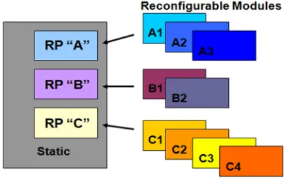
3.PARTIAL RECONFIGURATION
[image:3.612.325.531.338.468.2]Partial reconfiguration is a procedure of modifying an area in FPGA without changing any other applications. The functionality of the design flow, it is divided into two types: Static PR and Dynamic PR shown in figure 6. Static partial reconfiguration is inactive while configuring the device, data is loaded partially into FPGA other parts of the device are in shutdown mode. It reverts back to normal mode after reconfiguration process is completed. Dynamic partial reconfiguration is also known as active PR. It allows the change in functionality of a specific part of the device while the rest of the parts of FPGA are still running. Partial bit files are generated from the design flow using the process of Partial Reconfiguration [9].
Fig 6: Static and Dynamic Partial Reconfiguration
4.DYNAMICALLY RECONFIGURABLE
HARDWARE-SOFTWARE CO-DESIGN
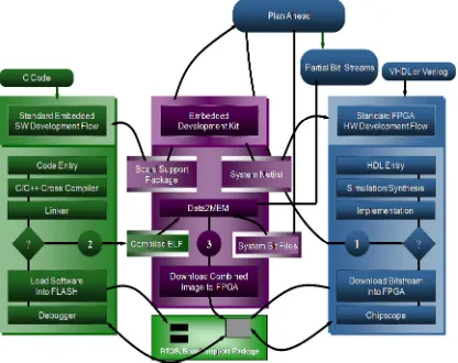
[image:3.612.92.298.365.572.2]2162 Ahead tool to produce multiple configurations with full and partial bit streams shown in figure 7 (a). Software Development Kit creates a C/C++ application which runs on processor generates Executable linkable Format (ELF) [11].
Fig 7 (a): Partial Reconfigurable Hardware-Software Co-Design Flow
Software control configures the FPGA in runtime through ICAP, loads the partial Bit files from CF card to Virtex FPGA rather than using impact tool to load manually. Then it dynamically reconfigures the device by issuing commands in serial communication.
5.PROPOSED PR BASED CRYPTOSTEM Cryptosystem is dynamically reconfigurable with
two active reconfigurable modules. Design
classification undergoes one static logic and more
reconfigurable modules. One reconfigurable
module for dynamic key generation for DES and
AES encryption techniques suitable in
cryptography applications which plays a vital role in data security. Second reconfigurable modules perform runtime inverse permutation for DES and Shift Rows for AES, which enhances the security shown in figure 7 (b).
Fig 7 (b): Proposed Dynamically Reconfigurable Crypto System
Several advantages with PR were, it reduces cost by time multiplex hardware and reduces the power by shutdown the specific area where application was not in use. It offers a flexible system allows customizing in implementing static and dynamic modules.
6.EVOLVABLE CRYPTO SYSTEM
In digital design evolvable hardware gains more popularity, it may be seen that FPGA’s are to be the target technology. Due to evolvable nature FPGA’s suitable for many applications like medical, image processing, configurable system on chip design for satellites, cryptography, digital logic design, gaming application and custom logic designs etc. FPGA internal architecture comprises of configurable logic blocks (CLB’s), routing resources and input output blocks. CLB complexity ranges from fine grain to coarse grain depend on architecture. Configuration can be classified into static and dynamic partial reconfiguration. Earlier FPGAs enable complete chip to reconfigure. With introduction to PR, only some (architecture) devices in Xilinx and Altera supports a portion of the chip to be reconfigured, while still remaining area of the chip retains their configured current design. In proposed design an Initial Permutation module in DES algorithm and Shift Rows or Shift Columns module in AES algorithm is partially reconfigured and algorithm is converted to DNA, mRNA. For every three triplets of mRNA amino acids form a protein sequence which enhances the security before transmission in a channel.
6.1 Data Encryption Standard (DES)
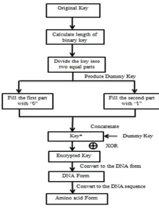
[image:4.612.92.300.162.327.2]2163 6.1.1 Importance of Key Cryptography
[image:5.612.122.281.174.383.2]A binary key of known size is considered. Divide the key into two equal halves to generate a dummy key. Figure 8 describes the Flow Chart for generating final encrypted key.
Fig 8: Flow Chart for generating final encrypted key
6.1.2 ALGORITHM
Step1: Consider a plain text message and Key of same size. Key is generated by using Partial Reconfiguration to enhance the security level of cryptography.
Step2: Reduce the key length to 56-bits using PC-1 and generate 16 sub-keys by shifting previous key. Step 3: By using PC-2 the sub-keys length will be reduced to 48 - bits shown in figure 9.
Step 4: From the Initial Permutation table the message which is to be encrypted is permuted configured using Partial Reconfiguration.
Step 5: This permuted message is now divided into two equal halves L0 and R0.
Ln = Rn-1– (Eq.1)
Rn= Ln-1 + F (Rn-1,Kn) -- (Eq.2)
Where function F involves in 3 sub-tasks. In first task, expansion of Rn is performed using E-Bit Selection Table. In the next task Rn-1 is Xored with Kn
(sub-key) whose bit length is 48 shown in equation 1 &
2.In the final task the output from second task is loaded into 8 s-boxes i.e., for each 6 bits.
Kn(+)E(Rn-1)= B1B2B3B4B5B6B7B8–(Eq.3)
where (+) represents xor operation from equation 3 Each
block Bn is given as input to the S-Box as shown
belowS1(B1)S2(B2)S3(B3)S4(B4)S5(B5)S6(B6)S7(B7)S8(B
8).
Step 6: These 8 S-Boxes gives 4-bit output which results 32-bit block. Now this block is considered as Rn. This process is repeated 15 times resulting in the generation of R16 and L16. Concatenation of R16 and L16 generates cipher.
Step 7: Each character in the Cipher is represented in the form of A, C, G, and T by using codon table.
Step 8: The DNA sequence is converted into mRNA sequence by replacing T with U. Finally protein sequence is generated from amino acids which are coded from RNA sequences.
Step 9: Key is divided into two halves Lk and Rk. If the bit length is odd for Lk, pad with 0 and if the bit length is odd for Rk pad with 1. After padding, concatenate Lk and Rk.
Step 10: Consider a dummy key along with the key obtained after padding. Perform XOR operation between key and dummy key shown in equation 4.
2164 Fig 9: Design flow of DES Algorithm
Step 11: Repeat steps 7-9 for key which results in protein form. The protein form is then converted to amino acid form.
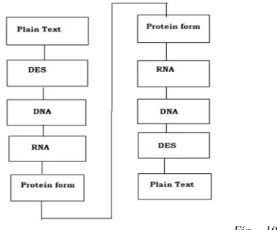
Step 12: Concatenate the protein form of cipher and protein form of key to generate the required Cipher shown in figure 10.
Fig 10:
DES Encryption algorithm using DNA Cryptography.
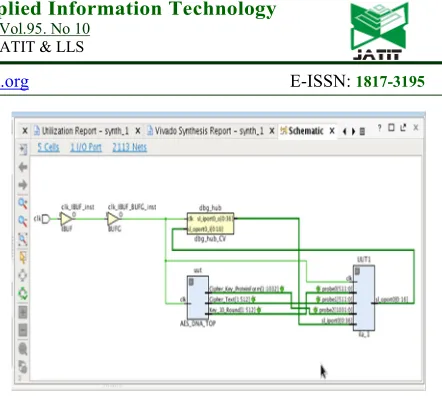
ILA cores are inserted to 64-bit DNA based DES algorithm to monitor internal signal shown in figure 11. Resources consumed after post implementation of 64-bit DNA based DES algorithm shown in figure 12.
Fig 11: Synthesized design of DES algorithm using DNA Cryptography with Internal Logic Analyzer (ILA)
Fig 12:Resources consumed for 64-bitDES algorithm using
DNA Cryptography
6.2 Advanced Encryption Standard (AES)
[image:6.612.326.525.281.424.2] [image:6.612.105.305.482.648.2]2165 rounds are attackable at any time so it is enhanced more in this paper through DNA technique.
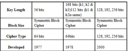
Table 2: Comparison of different Techniques
In AES, round key values for each individual round to perform the round key operation are generated through a separate key generation scheme. The key expansion has Rcon values and intermediate key values. Number of keys generated depends on the number of rounds present in encryption algorithm which in general depends on the bit size. For 128, 192, 256-bit keys there are 10, 12, 14 rounds respectively [14]. Here 128-bit message signal and key are taken in to account. DNA is applied to the AES algorithm after sub bytes operation which is done by using the tables shown in Fig 1. The added DNA sequence undergoes the consecutive operations. Encryption involves four transformations which are the basis points of the complexity of AES algorithm. The input message and key values are taken in the form of hexadecimal values into a 4*4 matrix. For 192 and 256 key lengths, the columns of the matrix increase to 4*6 and 4*8.
Fig 13: (a) AES Encryption and (b) AES Decryption Mechanism
The algorithm has the dynamism to adapt to any key length because of the constant rows which are always 4 in number. Any transformations that are performed depend on only number of rows in their calculations so that the column of the matrix is not affected. The
[image:7.612.326.532.346.449.2]transformations present are sub bytes, shift rows, mix columns, add round key. Initially the message signal and key bit are Xored with each other to obtain a single key. Then Sub Bytes, Inverse Sub Bytes tables are added to the sequence. In DNA, the tabular values are not completely loaded but they are added in the final stage there by reducing the complexity of Verilog code and improving its efficiency [15]. Figure 13 illustrated below depicts the systematic process followed to decrypt the original message. The shift rows transformation for 128 and 192 key lengths is performed by circular left shifting the rows. The number of shifts depends upon the row number from 0-3. This phenomenon changes for 256-bit length and it changes to 0, 1, 3, 4 shifts for the rows 0-3 respectively. The decryption mechanism involves inverse shift rows operation. Right circular shift is performed on the previous values and the number shifts and key lengths are same as that are done in encryption. The rows after shifting are clearly indicated in figure 14
Fig 14: Shift Rows
The entire data in algorithm modifies rapidly with the mix columns step. A different standard polynomial matrix is used for encryption and decryption separately. Here the code is implemented in a way that all the values depend up on a single .02 function which drastically reduces the implementation complexity. The .02 function is as follows shown in equation 5.
X . 02= X<<1 -- (Eq.5) (If left most bit of X is 0) = { X<<1 } XOR 0001 1011( If left most bit is 1)
[image:7.612.106.270.476.625.2]2166 key generation scheme are added at the end of each round. In the 10 rounds of 128-bit key, the final key do not involve mix columns step.
X.03= [X.02] XOR [ X]– (
Eq.6)
' 3 ' 2 ' 1 ' 0
P
P
P
P
=
02 01 01 03
03 02 01 01
01 03 02 01
01 01 03 02
*
3 2 1 0
P
P
P
P
Polynomial Matrix – (Eq.7)
[image:8.612.318.539.38.238.2]Po’= 02.P0 XOR 01. P1 XOR 01.P2 XOR 03.P3
Fig 15: Transmission of Cipher& Key merged in protein form through channel
The cipher generated along with tenth round key is transmitted across the channel by applying amino acids. Amino acids are the protein DNA forms which enhance the DNA bases further leading towards a perfect cryptographic sequence shown in figure 15. The 128-bit output of AES algorithm transforms into 256-bit output because of the addition of DNA after sub bytes mechanism. This DNA cipher is each divided into pairs of three and protein forms. Padding mechanism is entitled to the last pair to make them complete as three and to implement protein bases.
[image:8.612.97.295.199.505.2]Fig 16: Synthesized design of AES algorithm using DNA cryptography with Internal Logic Analyzer (ILA)
Fig 17: Resources consumed for 128-bit AES algorithm using DNA Cryptography
ILA cores are inserted to 128-bit DNA based AES algorithm to monitor internal signal shown in figure 16. Resources consumed after post implementation of 128-bit DNA based AES algorithm shown in figure 17.
[image:8.612.322.533.278.399.2]7.SIMULATION RESULTS
Fig 18: DES Encryption with DNA simulation using Xilinx ISE simulator.
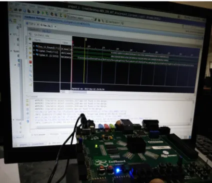
[image:8.612.322.538.530.571.2] [image:8.612.325.538.609.680.2]2167 Simulation output of 64- bit DES algorithm Key and Cipher in Protein form shown in figure 18. Simulation output of 128- bit AES algorithm Key and Cipher in Protein form shown in figure 19.
[image:9.612.322.538.44.254.2]8.FPGA IMPLEMENTATION OF INTERNAL VIEW OF CRYPTOGRAHY ALGORITHM USING CHIPSCOPE PRO ANALYZER
Fig 20: Place and Route occupancy of DES algorithm with DNA
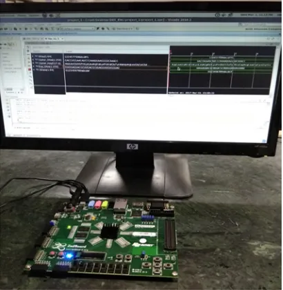
[image:9.612.91.301.192.413.2]Fig 21: Physical view 64-bitDES algorithm on Zync FPGA architecture.
Fig 22: Place and Route occupancy of AES algorithm with DNA
[image:9.612.324.532.284.444.2]Fig 23: PR based Dynamic Key Generation Mechanism
[image:9.612.93.298.456.666.2] [image:9.612.326.539.480.659.2]2168 Fig 25: Plan Ahead based dynamic key generation and runtime inverse permutation for DES / Shift Rows & Shift
[image:10.612.92.304.312.495.2]Columns functions for AES algorithm.
Fig 26: Physical view of 128- bit AES algorithm on Zync FPGA architecture.
Fig 27: Graphical comparison of Resources utilized for DES, AES Encryption Techniques with and without DNA.
Place and Route occupancy of DES algorithm with DNA is shown in figure 20. FPGA Implementation of 64-bit DES algorithm on Zync FPGA architecture is shown in figure 21. Place and Route occupancy of AES algorithm with DNA is shown in figure 22. PR based Dynamic Key Generation Mechanism for cryptography techniques are shown in figure 23 and 24. Plan Ahead based PR Floor Plan occupancy shown in figure 25. FPGA Implementation of 128 bit AES algorithm on Zync FPGA architecture is shown in figure 26. Device Utilization Summary comparison for DES, AES Encryption Techniques with and without DNA is shown in figure 27.
9. CONCLUSION
Evolvable cryptosystem is dynamically
reconfigurable with two active reconfigurable modules. Critical procedures to be followed in floor planning the design using reconfigurable partition, and defining pblock with physical constraints on floor plan for the location of Reconfigurable Modules and custom embedded processor using Plan Ahead tool to produce multiple configurations with full and partial bit streams. Design Rule Check and PR Verify procedures prove that global resources like DCM, IO Buffers etc.., should be avoided to generate partial bit streams. Design classification undergoes one static logic and more reconfigurable modules. One reconfigurable module for dynamic key generation for DES and AES encryption techniques, which plays a vital role in data security. Second reconfigurable modules perform runtime inverse permutation for DES and Shift Rows/Shift Columns for AES, which enhances the security. Protein bases are added to cipher and nth round key before transmission in a channel. Our proposed method is unique when compared with the traditional encryption techniques with DNA sequence. The encryption techniques are integrated with ILA cores to monitor internal view of signals using Chipscope Pro Logic Analyzer results are tested on Virtex XUPV5LX110T and Zynq Xc7z020 FPGA architecture. Resources utilized for DES, AES Encryption Techniques with PR and DNA occupies less resources in comparison without DNA.
REFRENCES
[1] Advances in Intelligent Systems and
[image:10.612.95.297.541.683.2]2169
[2] Sreeja C.S, Mohammed Misbahuddin,
Mohammed Hashim N.P,” DNA for
Information Security: A Survey on DNA Computing and a Pseudo DNA Method Based On Central Dogma of Molecular Biology”, IEEE 2014.
[3] Mona Sastry, Mohamed Hashem,
TaymoorNazmy, Mohamed EssamKhalifa; Design of DNA-based Advanced Encryption Standard (AES),. IEEE Seventh International Conference on Intelligent Computing and Information Systems, 2015.
[4] Yaser Jararweh,AES-512: 512-Bit Advanced
Encryption Standard Algorithm Design and Evaluation, IEEE, 2011.
[5] Chen-Hsing Wang, Chieh-Lin Chuang, and
Cheng-Wen Wu; An Efficient Multimode Multiplier Supporting AES and Fundamental Operations of Public-Key Cryptosystems, , IEEE Transactions on Very Large Scale Integration (VLSI) systems, vol. 18, No. 4, April 2010.
[6] AkankshaAgrawal, AkanshaBhopale, Jaya
Sharma, Meer Shizan Ali, and
DivyaGautam. Implementation of DNA algorithm for secure voice communication.
International Journal of Scientific &
Engineering Research 2012;
[7] Mona Sabry, Mohamed Hashem,
TaymoorNazmy. Three Reversible Data Encoding Algorithms based on DNA and Amino Acids Structure. International Journal of Computer Applications 2012; 0975 – 8887
[8] Zhang, Qiang, Wang, Qian, Wei, Xiaopeng.
A Novel Image Encryption Scheme based on DNA Coding and Multi-Chaotic Map. Advanced Science Letters; 2010; 3:447-451.
[9] M. Pranav, Archana K Rajan,“DES security
enhancement with dynamic
permutation”,International Conference
onApplied and Theoretical Computing and
Communication Technology,29-31 Oct.
2015, pp 6-11.
[10]F. Khan, N. Hosein, S. Vernon, and S.
Ghiasi, “BURAQ: A Dynamically
Reconfigurable System for Stateful
Measurement of Network Traffic,” Proc. IEEE Ann. Symp. Field-Programmable Custom Computing Machines, pp. 185-192, 2010.
[11]K. Papadimitriou, A. Dollas, and S. Hauck,
“Performance of Partial Reconfiguration in FPGA Systems: A Survey and a Cost
Model,” ACM Trans. Reconfigurable
Technology Systems, vol. 4, no. 4, pp. 36:1-36:24, Dec. 2011
[12]S.-F. Liu et al., “Increasing Reliability of
FPGA-Based Adaptive Equalizers in the Presence of Single Event Upsets,” IEEE Trans.Nuclear Science, vol. 58, no. 3, pp. 1072-1077, June 2011.
[13]Mohamed A. SeifEldeen , Abdellatif A.
Elkouny , SalwaElramly “DES Algorithm Security Fortification Using Elliptic Curve
Cryptography”, 2015 International
Conference on Computer Engineering & Systems,23-24 Dec. 2015, pp 335 -340.
[14]Mukta Sharma, Abdul Wahid
Ali“comparative analysis of npn algorithm & des algorithm”, 2015 international conference oncomputing, communication & automation,15-16 may 2015.
[15]SoufianeOukili, SeddikBri “FPGA
implementation of Data Encryption Standard
using time variable permutations”,