426
DEVELOPMENT OF MAZE ESCAPE ALGORITHM USING
RASPBERRY PI-BASED MOVING OBJECT FOR THE
SERVICES OF UNMANNED AUTOMOBILE
1SANG-CHUL KIM, 2GOO-HOON BYUN
1Professor, Department of Computer Science, Kookmin University, South Korea 2Research Associate, Department of Computer Science, Kookmin University, South Korea
E-mail: [email protected], [email protected]
ABSTRACT
In this paper, we developed a self-propelled vehicle using Raspberry Pi-based moving object that performs the mission to escape from the maze that will be used as key algorithms for the services of unmanned automobile. For the mission of maze escape, the line tracing and intersection discrimination algorithms have been developed using Raspberry Pi-based moving object. Various situations that occur during the experiments have been studied and solutions to solve them have been investigated. As the related research, a front collision avoidance system that avoids obstacles by recognizing the distances between moving object and obstacles when performing the mission of maze escape has been developed and a lane-keeping system between vehicles by employing various algorithms using the Raspberry Pi and Arduino–based moving objects was developed. Finally, we observed the experimental results between the left-hand and right-hand methods in the mission of maze escape.
Keywords: Raspberry Pi, Raspberry Pi-based Moving Object, Maze Escape, Right-hand Method, Motor
Control
1. INTRODUCTION
As the Internet of Things (IoT) is expected to grow bigger, the IoT based on the Internet has been applied in real life. Gartner, a US information technology research and advisory company, selected the IoT platform as one of the ten strategic technologies of 2016, and many companies are aware of the potential economic impact of the IoT [1].
IoT technology has a feature that combines the different industries and service domains based on Information and Communication Technology (ICT)-based skills. Service applications provided by the IoT have been used in various fields, such as health care, home care, safety, automotive, energy, environment, and agriculture [2]. Telematics is an IoT service application where combined wireless technology and GPS technology can provide a variety of services, such as location information, entertainment, purchase of products, and financial services in the automotive field [3]. In addition, unmanned automobile services are another area of IoT service application where the information from the external environment and a digitized map can
lead an unmanned automobile to its destination safely and follow the optimal path [4].
The development of algorithms for autonomous vehicle using the Arduino and Raspberry-Pi based moving objects has been increasingly interested nowadays [5]. Arduino is a single-board microcontroller based on open source and has been used in various IoT fields. Arduino can be used to develop a product that has a possibility of interaction between internal Arduino and the external environment by accepting inputs from sensors and controlling the output device, such as a motor or display. Since Arduino systems can be interoperable with Wi-Fi or Ethernet modules, Arduino is becoming increasingly popular in the IoT market [6].
427 device. With the help of assistance devices equipped by sensor based moving objects, hazardous driving situations caused by inexperienced drivers and various risks can be preemptively avoided [8]. Considering the possibility of causing a traffic accident due to the inexperience and slow reactions of older drivers, elderly-friendly unmanned vehicle technology is very attractive [9]. The Dijkstra algorithm is a representative algorithm to find a path that calculates the weights among the nodes for the route from the starting point to the destination point. When the sum of all the weights of a path is the lowest, the path is selected. When the obstacle is detected during the movement, the algorithm updates the total weight and searches for a route again. It has been considered that the circumstance where the autonomous car encounters obstacles, measures the time of Automatic Emergency Braking (AEB), and navigates another path when the autonomous car meets a sudden obstacle during driving [10].
Raspberry Pi, along with Arduino, is a
representative open-source hardware product using high-performance chips made by Broadcom [11]. In terms of hardware, it has more options than Arduino, such as a USB port, HDMI, and Ethernet port that can connect to a keyboard and mouse. Projects using Raspberry Pi are being conducted for education and research. Compared to Arduino, it also makes it easier to control motors and cameras and communicate with the Internet. A brilliant project costing just $35 using Raspberry Pi includes a Raspberry Pi wall calendar, temperature and humidity monitor, Raspberry Pi surveillance camera, and more. It is a suitable model for IoT product development. In this paper, autonomous moving objects are constructed through the versatility of Raspberry Pi, and maze-escaping missions are carried out by an autonomous moving object, which was developed using a Raspberry board [12]. The remainder of the paper comprises the following chapters. In Section 2, literature review has been discussed. Section 3 explains the proposed system architecture of the Raspberry-Pi based moving object. Section 4 shows the configuration of experiment setup and includes observations. Section 5 has been shown the differences and comparisons between the previous and proposed work as the observation. Section 6 reviews the suggested algorithm for the activity recognition, and future works.
2. RELATED WORKS
Research regarding the algorithm for steering and steering speed command has been conducted in the route aspect of unmanned vehicle because it was found that less steep steering changes are an important factor when avoiding obstacles to achieve more stable and efficient driving. In addition, a study on stable driving by calculating the collision time has been performed by anticipating the possibility of collision with another vehicle based on the information of location, speed, and acceleration of nearby vehicles and the road condition [13].
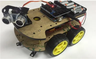
[image:2.612.321.513.409.528.2]Arduino Uno R3 board has been used as a control board to make the moving object for the route search and collision avoidance. This board plays a pivotal role in controlling the motors and detecting the lines by receiving signals from the infrared sensors. It is also connected to ultrasonic sensors to detect obstacles. The L298N driver, which is the most typical driver for controlling the motor in forward and reverse directions, was used. The moving object is composed of an automobile support, a sensor extension plate, a DC motor, a servo motor, an ultrasonic sensor, and an infrared sensor [14].
Fig. 1. Arduino-based Moving Object
428 the speed difference between the left DC motor and the right DC motor is returned to the line. Similarly, when the right sensor detects a black line, it returns to the line using the speed difference between the motors. If a black line is detected by the infrared sensor in the center, the speed of the two motors is controlled to be the same. However, in this way, the change of the manipulated variable is too large to allow flexible control. This problem can be compensated for by PID control, which is widely used [14].
Fig. 2. PID Control Graph
Proportional (P) control is a method through which the size is in proportion to the operation amount to the target value and the difference. P control can be implemented simply by multiplying the error signal by a proportional constant. However, P control alone causes residual frequency. Integral control removes the deviation by increasing the manipulated variable when accumulating a certain amount of accumulated residuals as time. If the previous deviation is large, Differential (D) control is used to return to the target value quickly.
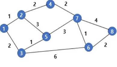
Fig. 3. The Distance between the Nodes
The Dijkstra algorithm is used to find the shortest path from the origin to the destination. It creates several node points and inputs the starting point and the destination into the moving object. Additionally, the distance between the nodes is input and the shortest distance is calculated using the Dijkstra algorithm. This algorithm is based on a first breadth search (FBS) and selects the node closest to the starting point as the first step. Then, the process of selecting the nearest node from among the distance to the node connected to the selected node and the distance to the node not selected from the previous node is repeated to calculate the total weight. If the destination node is selected through this process, the value is the shortest path to the destination [15]. The cases have been considered when experimenting where roads that are in motion are blocked or cannot be passed by obstacles. If the moving object on the path meets an obstacle, it moves to the previous node. Then, the node is set as a departure node, and the shortest path to the destination is rediscovered again. If the user can enter this information in advance in the moving object or in real time, they can drive to the destination more efficiently [16].
To control the distance between vehicle and obstacles and between vehicles, ultrasonic sensors are used. As the elderly drive more vehicles these days, the need for such a system is increasing. In addition, accidents caused by poor driving or sudden obstacles can also be avoided. The two actuators are driven at a constant distance. If the distance measurement value of the ultrasonic sensor is closer than a certain distance, it stops. If it is farther than the specified distance, it follows the path again. However, there is a problem in that it is difficult to distinguish an obstacle from an actuator by using an ultrasonic sensor alone. Therefore, there is a need to improve the moving object through image-processing technology using a camera sensor [16].
3. PROPOSED SYSTEM
In contrast to the moving object using
Arduino, the experiment and algorithm
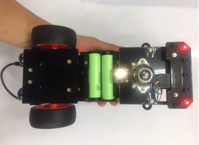
[image:3.612.100.294.564.676.2]429 Python. The L298N DC motor driver and PWM driver were used as the main components of the Raspberry Pi-based moving object, and a DC motor was used to drive the wheels. In addition, to detect obstacles, the servo motor was attached to the left and right sides. The previously manufactured Arduino based moving objects were problematic in the large-scale rotation and line tracing of the four-wheel drive. To solve this problem, we tuned Raspberry Pi-based moving object from four to three wheels and installed the front wheel of the moving object with ball caster. Furthermore, a color recognition sensor was installed to determine the target point. Finally, a five-way tracking module was installed on the front part of the moving object to enable the determination of the line and intersection.
Fig. 4. Raspberry Pi-based Moving Object-1
Fig. 5 Raspberry Pi-based Moving Object-2
One more thing needed to make a Raspberry Pi-based moving object was to be able to manipulate Raspberry Pi-based moving object on a remote PC. When we tried to develop in the
Raspberry Pi-based moving object itself, it needed a mouse, keyboard, monitor to connect to the Raspberry Pi, and the portability had also dropped. In order to solve this problem, we have taken the direction of controlling the Raspberry Pi-based moving object in the remote PC. The Raspbian OS we installed in Raspberry Pi enabled the operation of VNC Server because it has a Virtual Network Computing (VNC) Server installed by default. In addition, the fixed IP allocation method was used to allocate the same IP for each connection. The environment of the remote PC to connect to was the notebook where the Windows OS was installed. TightVNC software was installed on the notebook, and the wireless connection was successfully made using the basic port 5901 and the IP of the moving object. In addition to this method, Windows has a remote desktop program installed by default, so there is a simple procedure to connect to it. In addition, it is possible to connect through port forwarding by trying to connect from another network.
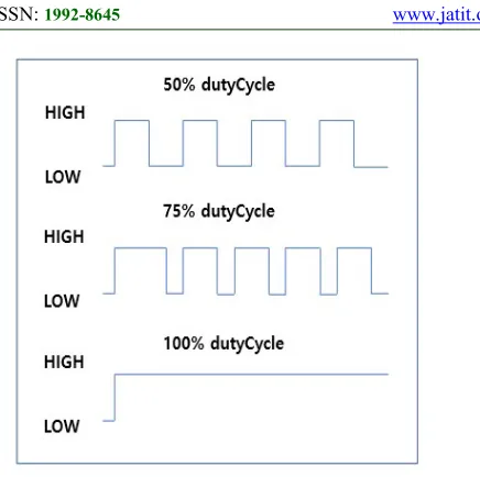
[image:4.612.90.291.515.662.2]430 Fig. 6 PWM Control Principle
PWM control is a method for controlling an analog circuit using a digital output. The voltage for using the motor was 5V, and the voltage can be determined by controlling the voltage level and quickly turning the digital output line off and on. For example, if the PWM duty cycle is set to 50%, the motor can be controlled at half the speed when 5v is the maximum speed. The necessary hardware for this is the L298N DC motor driver.
Figure 6 shows the basic setting code for PWM control in the Raspberry Pi-based moving object. Typical modules for GPIO control in Python are RPi.GPIO and WiringPi. In this experiment, the RPi.GPIO module was used. There are two ways to handle GPIO: GPIO.BOARD and GPIO.BCM (Broadcom chip-specific pin number). GPIO.BOARD is the number of the pins on the board, and GPIO.BCM is the number of the Broadcom chip. First, three GPIOs were assigned to the Raspberry Pi motor and the output was set. By default, the initial motor speed was set to 70% through the PWM start () method. In the code of Motor1A=12, 12 indicates the pin number of Raspberry Pi board, in the codes of Motor1A and Motor2A, 1 and 2 indicate the right motor and the left side motor respectively because the moving object has been composed of two motors.
Fig. 7 PWM Control
[image:5.612.95.313.72.289.2]431 Fig. 8 Basic Operation Algorithm
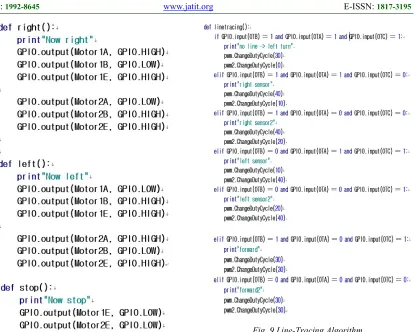
[image:6.612.110.525.72.404.2]Figure 7 shows the basic operation code we created for the mission execution. In forward () method, the code combination of GPIO.output (Motor1A.GPIO.HIGH) and GPIO.output (Motor1B.GPIO.LOW) causes the moving object to move forward. In backward () method, the code combination of GPIO.output (Motor1A.GPIO. LOW) and GPIO.output (Motor1B.GPIO. HIGH) causes the moving object to move backward. GPIO.output (Motor1E.GPIO. HIGH) and GPIO.output (Motor2E.GPIO. HIGH) codes drive the right and left motors respectively. The default action has been composed of a total of five methods where the forward () method moves forward for 2 seconds with the code of sleep (2), the backward () method backs up for 2 seconds, the stop () method pauses, the right () method turns right for 2 seconds, and the left () method turns left for 2 seconds. During this time, motor control, such as forward direction and reverse direction, can be achieved by adjusting the value of the motor to HIGH or LOW.
Fig. 9 Line-Tracing Algorithm
To perform the mission of maze escape, basically, a line-tracing function and an algorithm for determining an intersection were required. In the conventional Arduino actuator, three infrared sensors were installed to implement the line-tracing function. In the Raspberry Pi-based moving object, a five-way infrared tracking module was installed to perform line tracing during more precise intersection determination. We processed the remaining seven cases with the exception of one that could not be performed in eight cases that could result from three infrared sensors. The infrared sensor in the center detects white, and the infrared sensor on the left and right does not detect black. It is not processed because it can be resolved under different conditions even if it occurs. In all other cases, the speed of the left and right motors was appropriately set to recognize the line and follow it smoothly.
432 follows one wall, they will be able to navigate to all the places connected to that wall and find the exit.
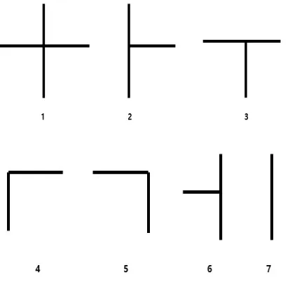
Fig. 10. Intersection Type of Maze
[image:7.612.311.515.140.314.2]4. EXPERIMENTS
Table 1: Sensor Value and Direction of Movement along the Intersection Type of Maze
In this experiment, the right hand method was mainly investigated. Figure 9 shows the types of intersection that can be seen in the maze experiment. Table 1 shows the sensor values and the direction of movement of Raspberry actuators according to the intersection type. If appropriate intersection decisions are made according to each
type and the correct direction of movement is taken according to the algorithm, one can move to the exit point.
[image:7.612.84.305.439.640.2]Fig. 11. Algorithm of Moving Object Performing Maze Escape
Figure 10 is a simple algorithmic diagram for the maze mission of the Raspberry Pi-based moving object. When the mission is started, it will detect the line and start line tracing. The Raspberry Pi-based moving object continues line tracing to determine what type of intersection it encounters. If an intersection is encountered, it rotates or straightens in the correct direction based on the sensor value and direction of movement according to the intersection of Table 1. If the current position is not the target point, the line-tracing algorithm is continuously operated, and if the current position is recognized, the mission execution is completed. A method for recognizing a target point is to use a color sensor mounted on an actuator. If the goal is given a recognizable color beforehand and the sensor recognizes the value corresponding to this color, the mission is successfully completed.
Fig. 12. Sensor Recognition of Intersection Type
The black line in Figure 11 represents the intersection, and the red line represents the location of the sensor for intersection detection. In the initial experiment, we found a problem of rotating to the left in the section to be rotated to the Type of
Intersecti on
Left Turn
Right Turn
Straight Path
Direction of Movement
1 True True True Turn right
2 False True True Turn right
3 True True False Turn right
4 True False True Straight
5 False True False Turn right
6 False False False U-turn
[image:7.612.316.532.565.646.2]433 right or to the right in the section to be rotated to the left. As a result of the investigation, it was found that if the Raspberry Pi-based moving object performed line tracing, it recognized the intersection as the first type in Figure 11. It was a T intersection, but was judged to be a left intersection because of the location of the sensor which are marked as red circles. Therefore, to recognize the intersection properly, the algorithm was configured so that the Raspberry Pi-based moving object could enter the intersection after stopping so that the other sensor could sufficiently recognize the intersection when entering it.
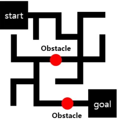
Fig. 13. Maze Map used in Experiment
[image:8.612.320.520.81.282.2]Table 2: Time Measurement Results by Left and Right Methods
Fig. 14. Experiment Result
Figure 12 shows the maze map created for this experiment. When the Raspberry Pi-based moving object starts at the start point and arrives at the goal point, mission execution is completed. Table 2 shows the time taken to implement the maze-escaping algorithm with the left and right hand methods. Left hand method took more time to escape from the maze than with the right hand method because of the lengthening of the driving range, and each experiment test took a similar time for each algorithm.
Based on the experiment, we found that it was possible to control the moving operation of Raspberry-Pi based moving object more precisely than the one of Arduino based moving object. When searching for a maze with a Raspberry Pi-based moving object, the performance metric such as the search time of each method has been determined by the shape of the maze. If the moving object operated with the correct algorithm, there was no difference in the time taken for each method.
5. OBSERVATIONS
In this study, a self-propelled vehicle using Raspberry Pi-based moving object that performs the mission to escape from the maze has been developed and the key algorithms will be used as the services of unmanned automobile. In terms of hardware, the existing four-wheel moving object was modified with a three-wheel moving object by mounting a ball caster in front of the moving object. The three-wheel moving object was able to rotate more accurately than the four-wheel moving object, allowing for more smooth line tracing. Also, by attaching an RGB sensor on the hardware floor, a three-wheel moving object made it possible to know whether the current Number of
experiments Left-hand method Right-hand method
1 101.32 seconds 93.44 seconds
2 101.44 seconds 92.87 seconds
3 102.98 seconds 93.23 seconds
4 101.02 seconds 94.02 seconds
[image:8.612.99.290.267.462.2]434 position is the target point or not. In terms of software, Arduino uses sketch to program and upload using a computer. Since we use 5-inch LCD monitor, wireless keyboard, and mouse, we can carry Raspberry-Pi based moving object with us and program it at any time. Raspberry-Pi uses Python code so we can get more popularity.
6. CONCLUSIONS
In this paper, we have experimented with algorithms and sensors for controlling motors using raspberry pi and various hardware. For the mission of maze escape, the line tracing and intersection discrimination algorithms have been developed using Raspberry Pi-based moving object. In addition, a front collision avoidance system that avoids obstacles by recognizing the distances between moving object and obstacles when performing the mission of maze escape was developed. Finally, the experimental results between the left-hand and right-hand methods in the mission of maze escape have been observed. When an obstacle was encountered while escaping the maze, an obstacle was detected and avoided using an ultrasonic sensor, and the target point was detected using an RGB sensor. If we know the map information in advance, we can determine which gives the shortest path between the right-hand and left-hand methods to provide the shortest path.
As a future research, an image processing algorithm will be adapted as the basic technology of autonomous driving technology. In the next experiment, we will study the line tracing algorithm where Raspberry Pi-based moving object follows the lane by measuring the slope of the lane recognized by the camera through the Hough transform. In order to obtain the slope value of the lane, we will install another camera that can see traffic lights, the blocking bars, and so on. If the current traffic light is on the road and the color of the current traffic light is red, Raspberry Pi-based moving object will stop. If it turns into green, the algorithm to start again will be executed in the Raspberry Pi-based moving object. In addition, if the blocking bar is on the road and Raspberry Pi-based moving object detects the blocking bar, it will stop and then start again. We will study many situations that may occur on the road as future research topics.
7. ACKNOWLEDGEMENTS
We would like to thank Mr. Ho-Sueng Lee for his great contribution to the experiment results.
REFRENCES
[1] I. Lee and K. Lee, "The Internet of Things (IoT): Applications, investments, and challenges for enterprises," Bus. Horizons, Vol. 58, No. 4, 2015, pp. 431-440
[2] F. Cicirelli, G. Fortino, A. Giordano, A. Guerrieri, G. Spezzano, and A. Vinci, "On the design of smart homes: A framework for activity recognition in home environment," J. Med. Syst., Vol. 40, No. 9, 2016, pp. 1-17 [3] P. Gope and T. Hwang, "BSN-care: A secure
IoT-based modern healthcare system using body sensor network," IEEE Sensors J., Vol. 16, No. 5, May 2016, pp. 1368-1376
[4] S. Adeyemi, E. Demir, and T. Chaussalet, “Towards an evidence-based decision making healthcare system management: Modeling patient pathways to improve clinical outcomes,” Decision Support Syst., vol. 55, no. 1, 2013, pp. 117–125
[5] G. Fico, A. Fioravanti, M. T. Arredondo, J. Gorman, C. Diazzi, G. Arcuri, C. Conti, and G. Pirini, "Integration of Personalized Healthcare Pathways in an ICT Platform for Diabetes Managements: A Small-Scale Exploratory Study," IEEE Journal of Biomedical and Health Informatics, Vol. 20, 2016
[6] J. Jeong, S. Yeon, T. Kim, H. Lee, and S.-C. Kim, "SALA: Smartphone-Assisted Localization Algorithm for Positioning Indoor IoT Devices," Wireless Networks, 2016 [7] T. Moranduzzo and F. Melgani, "Automatic
Car Counting Method for Unmanned Aerial Vehicle Images," IEEE Transactions on Geoscience and Remote Sensing, Vol. 52, 2014, pp. 1635-1647
[8] S. Wang, “Vehicle detection on aerial images by extracting corner features for rotational invariant shape matching,” in Proc. IEEE Int. Conf. Comput. Inf. Technol., 2011, pp. 171– 175
435 [10]K. Gray, L. Ibanez, S. Aylward etal., “Igstk: An
open source software toolkit for image-guided surgery,” Computer, Vol 39. No.4, 2006, pp. 46-53
[11]M. Bauer, B. Bruegge, G. Klinker et al., “Design of a component-based augmented reality framework,” in Proc. of International Symposium on Augmented Reality (ISAR), 2001
[12]V. Pardeshi, S. Sagar, S. Murmurwar, and P. Hage, "Health monitoring systems using IoT and Raspberry Pi — A review," 2017 Int. Conf. Innovative Mechanisms for Industry Applications (ICIMIA), 2017, pp. 134 – 137 [13]G. Pasolini, A. Bazzi, F. Zabini, "A Raspberry
Pi-Based Platform for Signal Processing Education," IEEE Signal Processing Magazine, Vol. 34, 2017, pp. 151 – 158
[14]S.-C. Kim, "Feasibility Study of Arduino-Based Autonomous Vehicles," The 8th International Conference on Internet (ICONI), 2016
[15]Z. Yaoming, W. Chengdong, Z. Yunzhou, F. Sheng, "Realization of moving object detection and tracking algorithm based on frame difference method and particle filter algorithm," 29th Chinese Control And Decision Conference (CCDC), 2017, pp. 161 – 166 [16]Y. Lin, Y. Tong, Y, Cao, Youjie Zhou, and