2017 International Conference on Mathematics, Modelling and Simulation Technologies and Applications (MMSTA 2017) ISBN: 978-1-60595-530-8
Development and Application of Power Network Simulation System for
Grid Connected Photovoltaic (PV) Generation System Test
De-shun WANG
1,2, Lian-tao JI
1,2, Bo YANG
1,2and Gui-gang HAN
1 1China Electric Power Research Institute, China, Nanjing, Nanrui Road 8, 2100032Jiangsu Engineering Technology Research Center for Energy Storage Conversion and Application,
China, Nanjing, Nanrui Road 8, 210003
Keywords: PV, Low Voltage Ride Through, Grid Connected Testing.
Abstract. In order to meet the need of photovoltaic power generation system testing, this paper presents a strategy for simulating grid fault, voltage and frequency fluctuations and other conditions, testing PV system grid connected adaptability and low voltage ride through capability. Main Topology of the control strategy using two PWM inverter units. By controlling the output voltage vector of two superimposed, analog grid frequency variation, voltage variation and harmonic power grid operating conditions. Control strategy according to the final prototype system was developed and applied to photovoltaic power generation field test, through practice verify the feasibility of the program.
Introduction
In recent years, photovoltaic (PV) generation has developed rapidly. The large scale of photovoltaic power generation, with volatility, strong randomness and poor immunity, will have a great impact on grid operation safety and stability. It is particularly important to improve the grid-connected PV generation system quality. The grid adaptability, low voltage ride-through and other performance requirements for grid-connected PV generation system are put forward in GB/T 19964-2012 <Technical requirements for connecting photovoltaic power station to power system>. Specifically, PV generation system must continue to operate with emitting active power or reactive power for supporting power grid. The voltage drop, voltage/frequency fluctuations and three-phase unbalance of conventional AC power grid occur randomly. Therefore, a power grid analogue power with variable frequency and variable frequency is needed to realize the simulation of various states of the power grid. Based on this, grid-connected performance testing of photovoltaic power generation system can be carried out, which can safeguard the safety of power grid.
In this paper, a grid analog power scheme with dual-inverter topology was proposed. Not only the two-way flow of energy with four-quadrant operation can be achieved, but also can provide independent output of three-phase grid voltage. The grid analog power can simulate various grid states and faults such as voltage sag, voltage and frequency fluctuation, unbalanced three phases. The control strategy of grid simulation system adopts fundamental mode and harmonic mode. The fundamental mode adopts dual closed-loop control scheme based on the instantaneous value of voltage and current. Harmonic mode with voltage effective value feedback control has good control effect and high stability. The prototype was finally tested in a photovoltaic power station in Qinghai, and the experimental results show that the control scheme is feasible.
Main Circuit Topology and Working Principle
the frequency, amplitude and phase of the output voltage of the two inverters, the output three-phase voltage can be adjusted.
Figure 1. Main circuit topology.
The output voltage of the two sets of inverters is respectively connected to the start and end of primary winding of the transformer. The winding voltage is the vector difference of the two inverters. When the harmonic test is needed, the inverter 1 can simulate the fundamental wave output of the power grid, the inverter 2 can simulate the power grid harmonics, and finally realize the harmonic situation of the simulated power grid, and test the harmonics adaptability of the photovoltaic power generation unit.
Control Strategy
Grid simulation test system includes rectifier control and inverter control sections. Rectifier part based on PWM control scheme with IGBT device, through the four-quadrant operation, photovoltaic power generation system can feedback energy to the power grid. Because the current on the AC side is time-varying under the three-phase rotating coordinates, the traditional PI controller cannot achieve no-dead-time tracking and need coordinate transformation. In order to change the amount of three-phase sinusoidal into a direct current, a common approach based on magnetic field orientation control method is converting the mathematical model in the three-phase stationary coordinate system into the synchronous rotating dq coordinate system in formula (1). Under above mathematical model, no static tracking of three-phase current will be realized.
rq q d s q s t q s rd d q s d s t d s u U i L i R d di L u U i L i R d di L (1)
In the PI adjustment result of each axis, a component containing other axis current information is injected. The injected component and the control object have the same coupling amount and opposite
directions. The feed-forward compensation is performed by using grid voltage Ud and Uq. Eventually,
Urd and Urq can be controlledusing the following functional relationship.
( )
( * )
*
il
rd ip d d s q d
il
rq iq q q s d q
K
U K i i L i U
s K
U K i i L i U
s
(2)
Kip and Kil are the proportional gain and the integral gain respectively, and i*d and i*q are given
values of id and iq. Available decoupling control block diagram of synchronous rotation d-q
coordinate system is shown in Figure 2. It can be seen that in the synchronous rotation d-q coordinate system, the current is a direct current and PI controller can achieve no static tracking.
Figure 2. Control Theory of PWM Rectifier Current
Inner Loop Decoupling. Figure 3. Control theory of bicyclic decoupling.
Grid analog system output is divided into fundamental mode and harmonic mode. The fundamental wave mode adopts the double closed loop control mode based on the instantaneous value of voltage and current. Figure 4 shows the double-closed-loop control block diagram. This method can not only meet the requirements of high-performance indicators, but also make the system to improve response speed and enhance stability. The introduction of negative feedback current feed-forward current in the current loop will speed up the dynamic response of the inverter, enhance the adaptability to nonlinear load disturbances, and reduce the harmonic content of the output voltage.
As the frequency of output voltage increases, the filter amplifies the output voltage. Therefore, the
high-order harmonic feed-forward factor 1-LCω2 is introduced to suppress the output voltage. Figure
5 shows the block diagram of the high-order harmonic control.
pwm
k 1
SL 1SC
*
o
u uo
0
u
o
i io
L i g u o u 1 dc U
1 1 k T
o
kT u t dt
T 0 ref U odc U p i
KK / s
pwm
k 1
SL 1SC
* o
u uo
0 u o i g u o u
1 1 k T
o kT u t dt
T 0 ref U odc U p i
KK / s
2
1LC
) sin( *
1 t un
Figure 4. Control diagram of fundamental mode
dual closed-loop. Figure 5. Control diagram of harmonic mode dual closed-loop.
Development and Testing
[image:3.612.379.474.602.711.2] [image:3.612.100.268.610.712.2]The main parameters of the grid simulation system are shown in Table 1. The output is independently controlled three-phase voltage and each phase voltage range is set to 0 ~ 500 V. Voltage output accuracy is 1% and the frequency output accuracy is 0.01Hz.
Table 1. Gird simulation test system parameters.
Filter inductance 150μH
Filter capacitor 500μF
Input voltage (690±15%)V
Output voltage 0~500V
Output rated current 0~1667A
Output voltage accuracy 1%
Output frequency accuracy 0.01Hz
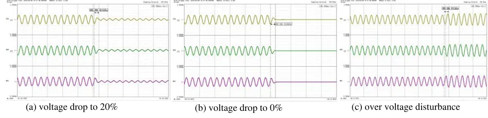
Figure 8 shows the voltage drop and over-voltage disturbance of the grid. Figure 8 (a) shows that the grid analog system drops from the rated voltage to 20% in 15ms, and in Figure 8 (b) , voltage drops to zero in 16ms, Figure 8 (c) describes 20% over-voltage disturbance with voltage rise time 15ms. It can be seen that voltage sag and the overvoltage perturbation process can be completed in one cycle (20ms) with the grid simulation system. This meet the requirements of the dynamic characteristics of the grid simulation system in GB / T 19964.
[image:4.612.74.548.301.416.2](a) voltage drop to 20% (b) voltage drop to 0% (c) over voltage disturbance
Figure 8. Output of three-phase voltage.
[image:4.612.108.509.500.617.2]Figure 9 shows the three-phase unbalanced output test waveform of the grid simulation test system. The figure shows the test results of setting the unbalance of 10% for Phase A.
Figure 10 shows the harmonic test waveform of the grid simulation test system, in which 3 times, 5 times and 7th harmonics are set for each 10V. Through testing by power quality equipment, the output meets the set value.
Figure 9. Output of A phase voltage unbalance. Figure 10. Output of voltage harmonics.
[image:4.612.322.503.503.617.2]Figure 11. On site test of Yellow River Hydropower Plant Photovoltaic in Gonghe County, Qinghai Province.
Figure 12 (a) shows the simulated grid frequency dropped from 50Hz to 48.05Hz and recovered to 50Hz after 15.67 seconds. The tested unit of the photovoltaic power station is not off-grid. Figure 12 (b) shows the frequency disturbance transient process. Due to the test channel frequency input using single-phase voltage test, the frequency test accuracy is not high. Therefore, the frequency from 50Hz down to 48.05Hz with transient recording test time about 25ms, but the actual inverter within 20ms to achieve rapid changes in frequency.
[image:5.612.255.498.289.399.2](a) The waveform of frequency test process (b) The waveform of frequency dropping process
[image:5.612.105.266.290.401.2]Figure 12. Frequency disturbance test of 47.5Hz.
Figure 13 simulates the grid the 70% voltage drop waveform by the grid simulation system, and then recovery to normal value after 2 seconds. As can be seen in Figure 13 (a), the PV unit to be tested is not off-grid and passed the 70% low-voltage ride-through test. Figure 13 (b) shows the instantaneous drop waveform, which drops from the rated voltage to 70% in about 13.6ms.
[image:5.612.115.510.475.590.2](a) The waveform of dropping process (b) The waveform of transient dropping
[image:5.612.345.508.478.588.2]Figure 13. Low voltage ride through test of 70%Un.
(a) The waveform of overvoltage disturbance process (b)The waveform of overvoltage trasient disturbance Figure 14. Over-voltage test disturbance test of 109% Un.
Conclusion
A grid-connected simulation system for PV power generation was proposed in this paper. The test system prototype meets the functions of low voltage ride-through, grid voltage and frequency adaptability, and successfully applies on-site testing of mobile photovoltaic power plants. It proves the feasibility of the topology and control strategy of the proposed grid simulation system and provides an important measure to ensure large-scale new energy sources to be safely connected to the power grid.
Acknowledgement
This research was financially supported by research on analysis and evaluation of DG penetration in distribution system (PD71-16-004)
Reference
[1] Wang Deshun, Yang Jun, Study on Measure to Restrain Transient Over-voltage in 35kV PV-LVRT Experiment [J]. High Voltage Apparatus. 2015, Vol. 51. No. 10: 0019-0023.
[2] Zhang R., Cardinal M. A Grid Simulator with Control of Single-phase Power Converters in d,q
Rotating Frame [C]. Power Electronics Specialists Conference. 2002: 1431-1436.
[3] Poh Chiang Lohan, Newman M.J. A Comparative Analysis of Multiloop Voltage Regulation Strategies for Single and Three-phase UPS Systems [J]. IEEE Trans. on Power Electronics, 2003, 18(5): 1176-1185.
[4] E.R. Collins. A Three-phase Sag Generator for Testing Industrial Equipment [J]. IEEE Trans. on Power Delivery. 1996, 11 (1):526-532.
[5] J. Carter, C.J. Goodman. Analysis of the Signal-phase Four-quadrant PWM Converter resulting in steady state and small-singal dynamic models. IEEE Proc Electr. 1997, 144(4): 241-247.
[6] Fan Shengfang, Xiong Jian, Zhang Kai, He Liqun, Zhao Wencai. A Decoupling Control Scheme of High Power Four-quadrant Converters for Traction [J]. Proceedings of the CSEE. 2012, Vol. 32 No. 21, p. 63-p. 32.
[7] Yao Jun, Liao Yong, Zhuang Kai. Coordinated Control Strategy of Back-to-back PWM Converter for Permanent Magnet Direct-driven Wind Turbine. Automation of Electric Power Systems, 2008.Vol. 32 No. 20, P.88-92.