Systems Reference Library
File Number GENL-22 Form C24-3258-2
Autocoder (on Disk) Language Specifications
IBM 1401, 1440, and 1460
This reference publication describes the Disk Autocoder
programming system for IBM 1401, 1440, and 1460. The first section contains the specifications of the symbolic language of
Autocoder (mnemonics, labels, address types), a description of declarative, imperative, and assembler control operations, and the rules for writing the source program. The second section
M a;or Revision, April 1966
This publication, C24-3258-2, is a major reVlSlon of, and obsoletes C24-3258-1 and Technical Newsletter N21-0038. Revisions to the text are indicated by a vertical line to the left of the chanped text; revisions to the figures are indicated by a bullet (.) to the left of the figure caption.
Copies of this and other IBM publications can be obtained through IBM Branch Offices. Address comments concerning the content of this publication to:
IBM, Product Publications Department. Rochester, Minn. 55901.
Contents
Language Specifications ... ... 5
Machine· Requirements .... ... ... .... ... 5
Related Information .... ... ... 5
Programming with Autocoder ... 6
Source Program ... ... ... .... ... ... 6
Assembler ... .... ... .... ... ... 6
Coding Sheet ... ... ... ... ... ... 6
Writing Autocoder Statements ... 8
Labels ... 8
Operation Codes ... ... ... 8
Operands ... 9
Statement Descriptions ... 16
Declarative Statements . ... ... ... ... ... ... 16
Imperative Statements ... 22
Assembler Control Statements ... 24
Macro System . ... ... ... ... ... ... 31
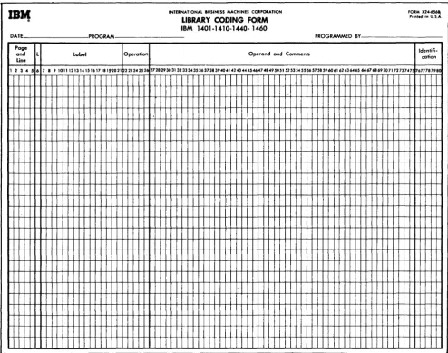
Library Routines .... ... ... ... ... 31
Macro Instructions .... ... ... ... ... ... ... 31
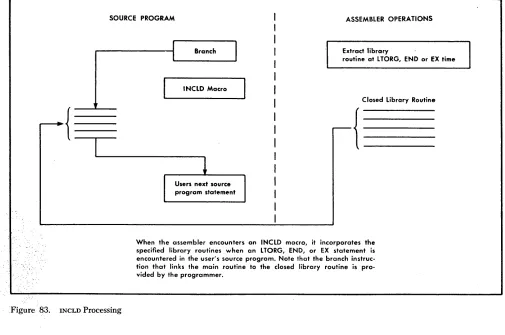
INCLD Macro ... 34
CALL Macro ... 34
CHAIN Macro ... ... 36
MA Macro - Modify Address .... ... ... ... 36
LOOP Macro ... ... 37
COMPR Macro ... 38
Linkage Macros ... ... ... ... ... ... 38
Arithmetic Macros .... ... ... ... ... 39
Developing Library Routines ... 42
Model Statements .... ... ... ... ... 42
Special Requirements for INCLD Library Routines ... 44
Pseudo Macro Instructions ... 45
Librarian Control Operations ... 49
Appendix ... 51
The Disk Autocoder system is designed to simplify the programmer's task. Instead of coding program state-ments in machine language, he can write symbolic statements that comprise an Autocoder source pro-gram. The source program is input to an assembler program, which is supplied by IBM, that translates the source statements into machine language and produces an object program.
The Disk Autocoder language includes the follow-ing significant features:
• Mnemonic operation codes that are more easily remember~d than the actual machine-language op-eration codes.
• Symbolic operands that eliminate actual core-storage address assignment and reference.
• Literal operands that eliminate prior definition of actual constants.
• Area-definition statements that allocate core storage for constants and work areas.
• Assembler-control statements that allow the pro-grammer to exercise some control over the assembly process.
• A macro facility that eliminates repetitive / coding of general routines. By writing a single instruction (macro instruction), the programmer can specify that a routine be extracted from the Autocoder library and incorporated in his program.
Machine Requirements
The Disk Autocoder system requires the following minimum machine configurations.
IBM 1401 System
4,000 positions of core storage High-Low-Equal Compare Feature One IBM 1311 Disk Storage Drive One IBM 1402 Card Read-Punch One IBM 1403 Printer
Language Specifications
IBM 1440 System
4,000 positions of core storage
One IBM 1301 Disk Storage or one IBM 1311 Disk Storage Drive
One IBM 1442 Card Reader
One IBM 1443 or 1403 Printer
IBM 1460 System
8,000 positions of core storage
One IBM 1301 Disk Storage or one IBM 1311 Disk Storage
Drive
One IBM 1402 Card Read-Punch One IBM 1403 Printer
The Autocoder System can utilize the following devices and features if available:
IBM 1444 Card Punch IBM 1404 Printer
Console Printer
8,000, 12,000, or 16,000 positions of core storage Print Storage feature
Direct Seek feature (for a library change only)
The system on which the object program is to be executed must have:
• A card reader or a disk unit to load the object pro-gram.
• Sufficient core storage to contain the object program.
If the object program requires more than the avail-able core storage, the program must be executed in sections (overlays) or the job must be divided into multiple runs.
• The devices and special features specified in the object program.
• The high-low-equal compare feature, if the MLTPY
macro, the DIVID macro, or the clear option (, C) of the DA statement is in the program.
Related Information
One of the following SRL publications should be used in conjunction with the Autocoder language specifi-cations:
System Operation Reference Manual for IBM 1401 and 1460, Form A24-30B7.
System Operation Reference Manual for IBM 1440,
Form A24-3116.
Programming with Autocoder
Source Program
The source program consists of statements written in symbolic langtlage . Disk Autocoder symbolic language permits the programmer to define areas, write in-structions, call in library routines, and exercise some control over assembler operations.
The Disk Autocoder language includes a standard set of mnemonic operation codes for declarative, im-perative, and assembler "control operations.
The mnemonics used in imperative statements are more easily '-"remembered than the machine-language operation codes because they are usually abbreviations for the actual instruction. For example:
Machine-Language Instruction Mnemonic Code
Multiply M @
Clear word mark CW J:l
The mnemonics used in declarative and assembler control statements have no machine language equiv-alent.
Source-program statements are written using mne-monic operation codes and the names given to data, instructions, and constants. Literals (actual data to be operated on during processing) can also be written in the instruction statements that use them.
The information contained in Autocoder statements is divided into four categories:
1. Area definition (declarative operations). The
area-definition entries are used to assign sections of storage for fixed data (constants) that will be needed during processing, to set aside work areas, and to assign symbolic names to data, devices, and areas used in the program.
2. Instructions (imperative operations). The
instruc-tion entries state, symbolically, the operainstruc-tions to be performed by the object machine. ADD, SUBTRACT, READ, and PUNCH are examples of imperative opera-tions.
3. Control Statements (assembler control operations).
The disk Autocoder system permits the programmer to exercise some control over the assembly process. For example, the programmer can specify the be-ginning address of the object program and the core-storage capacity of the object machine.
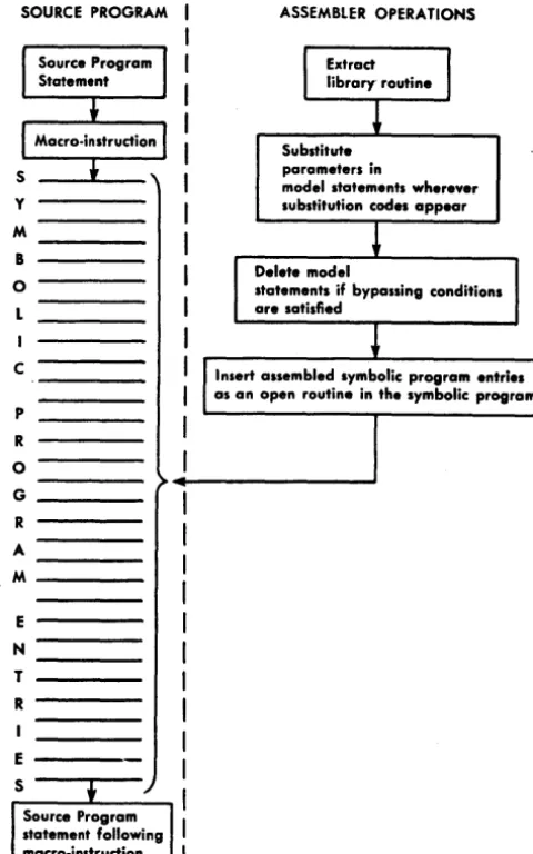
4. Macro Instructions (macro operations). Macro
structions are used to call out standard sets of in-structions (routines) from the library that is stored 6 Autocoder (on Disk) Language Specifications
on disk. During program assembly, the assembler can extract the routine associated with the macro instruction, tailor it to fit the program requirements, and insert it in the object program.
-Assembler
The Autocoder Assembler Program operates under the direction of a System Control Program. The functions of this control program are to coordinate system func-tions and to handle input! output device assignments.
The Autocoder Assembler is a multiphase program designed to translate Autocoder statements into ma-chine language. At assembly time, the source program is read into core storage from cards or dis~. The System Control Program reads the Assembler Program into core storage from the disk unit that contains the Autocoder system.
The first step in the translation process is performed by the macro-generator phases of the Assembler Pro-gram. These phases examine source-program macro instructions, extract the associated library routines, and generate Autocoder statements.
The Assembler then analyzes all Autocoder state-ments during a diagnostic phase. A diagnostic listing of all invalid statements is printed if the user specifies the option in his control card for assembly (CTL card). A programmed halt occurs after the diagnostics have been printed. The user can make corrections and re-start the assembly, or he can continue processing.
After the macro instructions have been processed and the Autocoder statements have been analyzed, the Assembler translates the Autocoder statements into a machine-language object program. The object pro-gram is punched into cards or written in disk storage, depending on the specifications in the user's control cards.
Coding Sheet
Disk Autocoder statements are written on a coding sheet that is designed to organize them into the for-mat required by the assembler. Figure 1 shows the Disk Autocoder free-form coding sheet.
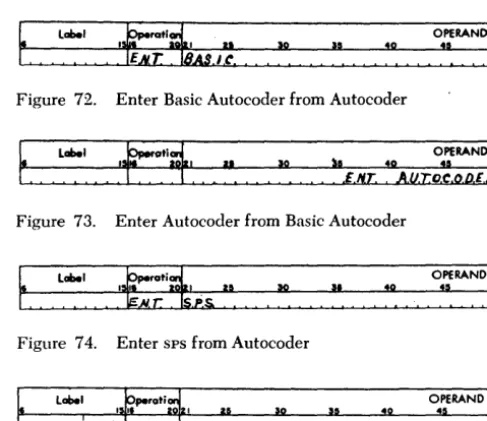
Although the assembler can process statements coded in 1401 Symbolic Programming System (sps) and 1440 Basic Autocoder lanuguages (see ENT-Enter New Coding Mode), this publication refers
primarily to the coding of Disk Autocoder language.
IBM
Form X24-13S0<!l Printed in U.S.A.
Program
INTERNATIONAL BUSINESS MACHINES CORPORATION Identification '
Programmed by
-
AUTOCODER CODING SHEET 76 80Page No.W of _ _
Date IBM 1401-1410-1440-1460
Line label Operatior1
,
.56 1516 20121 2S 50 3so I
:
02
:
03 :
04 :
05 :
06
l
07
l
I
08 I
09
:
10 I
I
I I
I
I 2 I
13
:
14 :
I
I 5 I
16 I
I
17 I
I
18 I
I 9 :
I
20 I
I
2 I I
2 2
:
I2 3 I I
I
2 4 I
I
25 I I I
I
I I
I
I I
I I
I
I I
I
Figure 1. Autocoder Coding Sheet
Write all source-program statements and comments on the coding sheet. Column numbers on the sheet indicate the card-punching format for all the cards in the source deck. Punch each line of the coding sheet into a separate card.
The function of each portion of the coding sheet is explained here.
Page Number (Columns 1 and 2)
Write the sequence number of the coding sheet in this field. These numbers should be arranged according to low-to-high collating sequence. Any character that is valid for IBM 1400 series systems can be used. Refer to
the IBM character-code chart in the System Operation Reference Manual.
Note: Do not use an asterisk in column l.
40
I
I I I
OPERAND
45 50 55 60 65 70
·
·
·
I I
J-L....!.
....L....L •
Line Number (Columns 3-5)
Use this field to indicate the sequence of entries on the coding sheet. The units position of this field may be left blank. It can be used later to indicate the se-quence of inserts on a page. The five unumbered lines at the bottom of a page can contain these inserts.
For example, number the first insert between lines 02 and 03 "025". Number later inserts at that point so that they can precede or follow the first insert, as required. Numbers on the coding sheet need not be consecutive; but, when the source deck is used as in-put to the assembler, the cards should be in low-to-high collating sequence.
Label (Columns 6-75)
A label can have as many as six alphameric (A-Z or 1-9) characters, but the first character must be
alpha-betic. Special characters and blanks must not be used within a label.
The label usually starts in column six. See Define Constant with Word Mark for exception. Any
subse-quent references to the labeled item must correspond to the name used in the label field of that particular item.
Columns 13-15 are not checked.
Operation (Columns 76-20)
Write the mnemonic or machine-language operation code in this field.
Operand (Columns 27 -72)
Two operands and a d-character may be written in this field. An operand designates a core-storage ad-dress, an input/output unit, or a constant to be de-fined. A d-character modifies an operation code. It is a single alphabetic, numeric, or special character.
The operands and the d-character must be separ-ated by commas because the Disk Autocoder coding sheet is free-form (the operand and d-character fields are not fixed fields).
Comments
The programmer can include a remark anywhere in the operand field if he leaves at least two non-signifi-cant blank spaces between it and the operand.
To include a whole line of information anywhere in the program, write a comments line that contains an asterisk in column 6 and the comment in columns 7-72. Columns 6-8 should not contain 0< 1 0<. (0< 1 0< ill' columns 6-8 will cause a diagnostic to falsely appear during assembly.) A punched card containing a comments line is called a comments card. The information punched in the comments card appears in the sym-bolic-program listing produced by the assembler, but it does not affect the object program in any way.
Columns 73-75 are not checked. IdentificatiC!)n (Columns 76-80)
Write an identification name or number in this field to identify a program or program section (overlay). Punch the contents of this field into each card in the source deck. The identification appears on the sym-bolic-program listing but does not affect the object program in any way.
Writing Autocoder Statements
Three types of information can be specified in Auto-coder statements: labels, operation codes, and oper-ands.
8 Autocoder (on Disk) Language Spec~fications
Labels
Labels are descriptive terms selected to identify a specific area or instruction in a source-program state-ment. A label that suggests the meaning of the area or instruction makes coding easier. It also makes the program more easily understood by others. For ex-ampLe:
Type of Statement Meaning Label
Area Definition Withholding Tax WHTAX
Instruction Update UPDATE
When the assembler processes a source-program statement, it assigns an address and allocates storage for the instruction or defined area. If the statement has a label, the assembler equates the label to the assigned address. In this publication the assigned address is called the equivalent address.
The equivalent address of the label for an instruction
is the leftmost (high-order) core-storage position of the area the assembler has allocated for it. For example, an instruction whose label is ENTRYC is located in core-storage locations 549-552. The equivalent address of ENTRYC is then 549.
The equivalent address of the label of an area-definition statement is usually the rightmost (low-order) core-storage position of the area the assembler has allocated for the constant or work area. (See
DCW Define Constant with Word Mark and DC -Define Constant (No Word Mark) for exceptions.) For
example, in a DCW statement a constant whose label is
RATE is located in core-storage positions 420-424. The equivalent address of RATE is then 424.
During, processing the assembler maintains a table of labels and their equivalent addresses.
If a label appears in any Autocoder statement, it may be written as an operand in any other Autocoder statement. During processing, the assembler substi-tutes the equivalent address of the label whenever the label appears as an operand in a source-program statement. Thus, the programmer refers symbolically to th~ equivalent address of the constant, work area, or instruction.
Operation
Codes
Most-Autocoder statements have operation codes. (See
Subsequent DA Entries for an exception.) In
impera-tive instruction statements they are machine-operation codes such as A (ADD), s (SUBTRACT), SD (SEEK DISK), and P (PUNCH).
In area-definition statements they are commands to the assembler to allocate storage, such as DCW (D~fine
a Constant with a Word Mark and DA (Define Area).
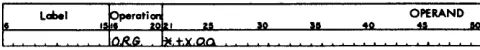
In assembler-control statements, they are signals to the assembler such as ORG (begin or originate the program) and END (end the program).
The appendix of this publication contains charts that list all valid mnemonic operation codes.
Operands
Use the operand portion of an Autocoder statement to specify:
1. For instruction statements: the address of the data
to be operated on or the input/output units to be operated, and the d-character modifier to the op-eration code, if required.
(A list of all valid operand sequences is included in the Appendix.)
2. For area-definition statements: the constant or area
to be defined, or the address or input/output unit that is to be the equivalent of the label.
3. For assembler-control operations: the address to
be used in a particular assembler operation.
Core-Storage Address Operands
There are five types of address operands used in Auto-coder statements: symbolic, actual, asterisk, blank, and literal.
Symbolic
A symbolic operand refers to the equivalent address of an instruction or defined area. The symbolic oper-and must be the same as the label of the instruction or area-definition statement. Writing a symbolic oper-and in a statement that precedes the labeled statement is permitted.
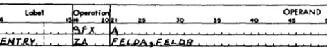
In Figure 2, ENTRY A is used as a label for an ADI) instruction and as a symbolic operand in a branch instruction. Assume that the equivalent addresses of ENTRYA, WHTAX, and DEDUCT are 568, 701, and 905 respectively. The assembled machine-language in-structions would be A 701 905 and
Il
568. In a pro-gram using these instructions, WHTAX and DEDUCT would be used as labels elsewhere in the program.label 15 ~peroti: I OPERAND
,
2S lIO lI5 4Q U 50I£/'I,T ftY.A A Ww,,.,A.,1l, ,D,I;, D.V.C.T.
I
·
I·
I
·
I
B. E..N:r.R,Y.A.
Figure 2. Symbolic Operand
Actual
The programmer may use an actual address as an operand in any Autocoder statement. This address is a one-to-five digit number within the range 0 to 15999, and represents an actual core storage position.
For example, to cause a word mark to be set in location 001 during execution of the object program, write in the source-program the instruction shown in Figure 3. Note that it is not necessary to write high-order zeros in an actual address written in Autocoder.
label OPERAND
~O
:5
~Figure 3. Actual Address Operand
Asterisk
Writing an asterisk in an Autocoder statement directs the assembler to assign an address equivalent to 'the right-most (low-order) position of the area that the instruction or data will occupy in the object machine.
lobel 15~peroti: I OPERAND
2S so S5 40 45 50
C!,0I'1 P.R. I C AL"":~
I
A,Y, rO.TA,L.. I
·
I
·
I
·
IT.O,T,A.,L I lA, l*-~ ,(0.1') IIAI T
Figure 4. Asterisk Operand
Figure 4 shows a routine designed to compare field-A to field-B, and to add 1 to a field named COUNT
if the result is unequal. Assume that the equivalent addresses of TOTAL and COUNT are 459 and 711 re-spectively. The asterisk then refers to 465, which is the address of the low-order position of the seven-character assembled instruction and *-6 refers to 459. The assembled instruction is A 459 711. When the instruction is executed, one is added to COUNT because 459 is the address of the operation code (A). In core storage, an A is composed of A- and B-zone bits and a
I-bit; these zone bits form the standard plus sign, and do not change the addition of the numeric 1. Figure 5 is a representation of the instruction in core storage during program execution.
Character 8 4 5 9 7 1 1
Core Storage
459 460 461 462 463 464 465
Location
Blank
Blanks are valid in statements where no operand is needed, or when useful addresses are supplied by the chaining method. Chaining is explained in the System Operation Reference Manual.
Literals
A literal operand 'is the actual data to be used when the instruction in which it appears is executed. The assembler stores the actual data (constant) with a word mark over the high-order position when it en-counters a LTORG, EX, or END assembler-control state-ment. The equivalent address of the stored constant is substituted for the literal operand when the instruc-tion is assembled. The programmer can address-adjust and/ or index a literal. See Operands: Address-Adjust-ment and Indexing.
1
Duplicate literals are assigned core-storage space only once per program or program section. When a literal is referred to, a program section means those source-program entries that precede a LTORG, EX, or END assembler-control statement.
Figure 6 shows literal operands and the constants produced for them.
Type
of Literal Stored
Literal Operand Constant
Numeric +10 11
Alphameric @JANUARY 28, 1962@ .!ANUARY 28, 1962
Area-Defining WORKAR#6 bbbbbb
Address Constant +CASH !XX (Equivalent
Address of CASH)
Figure 6. Literals
Numeric Literals. A numeric literal must be made up of integers only (0-9) and must be preceded by a plus or minus sign. The sign is necessary because the assember uses it to distinguish numeric literals from actual addresses. The literal may be any length, provided that it is contained in the operand portion of one program card. The sign is stored in the same core-storage position as the units position of the numeric literal.
Figure 7 shows how a numeric literal can be coded in an Autocoder imperative instruction. Assume that the literal (+10) is assigned storage locations 584 and 585, and INDEX is assigned an equivalent ad-dress of 682. The symbolic instruction causes the assembler to produce a machine-language instruc-tion (;1 585 682) that adds +10 to the contents of INDEX when the instruction is executed in the object program.
10 Autocoder (on Disk) Language Specifications
label ~perati~
I I I 5 0
. =,", o,~, NDIEX~
OPERAND
:5
:
Figure 7. Numeric Literal
Alphameric Literals. An alphameric literal is one or more alphameriC characters written between two @ symbols. Alphameric characters include numeric, alphabetic, and special characters ( including blanks). Any combination of alphameriC characters can be used within the two @symbols, with the following .r~strictions:
1. If the object program is to be punched into cards in the condensed-loader fonnat, a word-separator character (0-5-8 punch) should not be the first character following the first @ symbol.
2. If the object program is to be written on disk (coreload
fonnat), a group mark should not be the first character fol-lowing the first @ symbol.
(Object-program formats are described in the publication;
Autocoder (on Disk) Program Speci!iications and Operating Procedures, IBM 1401, 1440, and 1460,
form C24-3259.)
Only one alphameriC literal is permitted in a co-ding-sheet line. One or more @ symbols can be included within an alphameric literal (between the two @ symbols enclosing the literal), but an @ symbol must not appear anywhere else in a line containing an alphameric literal. The assembler scans the contents of the card from the left for the first @ symbol and from the right for the second @ symbol. All characters between the two @ sym-bols are assumed by the assembler to be part of the literal.
Figure 8 shows how to use an alphameric literal in an imperative instruction. Assume that during assembly the literal JANUARY 28, 1964 is assigned a storage area whose equivalent address is 906, and DATE is assigned 230. For this statement, the assem-bler produces a machine-language instruction (M 906 230) that moves the literal JANUARY 28, 1964 to DATE.
label
Figure 8. Alphameric Literal
Address-Constant Literals. An address-constant lit-eral is the label of an instruction, defined area, or constant preceded by a plus or a minus sign. A plus sign preceding the label indicates that the constant represented by the literal is the machine-address the assembler assigns to the label. A minus
sign preceding the label indicates that the constant represented by the literal is the 16,000's comple-ment of the machine-address assigned to the label. The address assigned to any label, except labels
associated with area-defining literals, can be
repre-sented as constants by address-constant literals. (Area-defining literals are described in the follow-ing section. )
When the assembler encounters an address-constant literal, it:
1. Allocates a three-position area that will contain the equiv-alent address or its 16,000's complement at object-program execution time. (The equivalent address is a three-charac-ter machine-language address.)
2. Assigns an address to the allocated area and equates the address-constant literal to the assigned address.
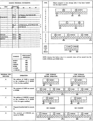
Figure 9 shows two address-constant literals (+ CASH and
+
CHECKS) used in a source program. It also shows the entries the assembler makes in the object program, and the results when the instruc-tions are executed by the object program. Thepro-SOURCE PROGRAM STATEMENTS TYPE Object program in core storage after it has been loaded into the object machine.
Label pperotiCl!'
30 ~
6 1516 20 I 25
·
II
0
I®
ENTRYI II
·
NI
·
S 1~171917 410141~1010101611121,
IMLC. ~('ac,,&J ,: IIT.Il.'II..1.+.3. A T 3~4 401 404
1=.IIlTR.'IIi' IM.L.C 1/).wOJ2.~ B R
,
·
U,
·
C,
·
T1
~
lal 0I~
41 0 141 !14~
11 1,
MLC. +.C IH' ,.VC.~NTR~.1.+3c C I
,
R ~.N. T.fVI.'i. D 0
•
•
N 501 50S
·
, S
·
~A.51-L : n.r.w. 1I;t.. E A
I ®CASH ®CHECKS I @ WORK
J
t>.HU'J<.S: DC.I.!. #,to. F R1~lblblblblb~lblblblblbl~lblblbl~~
.lll.R.1l'. , O('.LJ *.t. G E
, A 6l>0 606 612
, S
,
ADD.
I
+CASHI
+CHECK~ CON.LIT· 1~10101~1016J
ERALS 797 aoo
EQUIVALENT
SYMBOLS ADDRESSES NOTE: Assume that before step A is executed, data will be moved into the CASH, CHECKS and WORK fields.
ENTRYI 401
CASH 600
CHECKS 606
WORK 612
+CASH 797
+CHECKS aoo
PROGRAM STEP CORE STORAGE CORE STORAGE
EXECUTED OPERATION BEFORE OPERATION AFTER OPERATION
A The address of CASH is moved
I (~) ENTRYI 1 I
CtD
ENTRYI I to the A·address of B (ENTRY1 +3). B is thus modified. I~IO 01 0 1 6 1 1 121 1~1610101611121
401 404 401 404
B The contents of CASH are moved
I
®CASHI
@ WORK 1.1 (E) CASHJ
(G) WORKI
to WORK.1.~16191a17 51010141010101 :1216191 a 17151216191S17151
600 612 600 612
The address of CHECKS is moved C
I
(B ENTRYII
I
(B) ENTRYII
to the A-address of B (ENTRY1 +3). B is again modified. ~ 1610 01 6 1 1 1 2
I
~1610161611121401 404 401 404
D Program branches back to execute
B. NO CHANGE NO CHANGE
B The contents of CHECKS are
I (F) CHECKS I (G) WORK. I I (F) CHECKS I (G) WORK
J
moved to WORK.I~I 0171 a l9121216191S17151 1~1017IaI9121~1017ISI9121
606 6i2 606 612
[image:11.613.68.451.203.706.2]grammer did not know what addresses would be
as-signed to CASH and CHECKS when he wrote the
source-program statements. He did, however, write
two instructions (A and c) that move these addresses
into instruction B (ENTRY 1). The address-constant
literals
(+
CASH and+
CHECKS) caused theassem-bler to allocate storage in the object machine for
equivalent addresses of CASH and CHECKS and to
substitute the addresses of the address-constant
literals in instructions A and c.
Autocoder permits the programmer to adjust an equivalent address. To use the adjusted equivalent address, code the address-constant literal as follows:
1. Plus or minus sign. 2. Period.
3. Label whose equivalent address is to be adjusted. 4. Adjustment factor (plus or minus any integer that will
produce a number greater than zero, but less than the number of core-storage positions available in the object machine) and/or an index-register symbol.
5. Period.
Figure 10 shows an equivalent address that is modified by an adjustment factor. Assume that the
equivalent address of TOTAL is 565. When the
in-struction is executed 561 will be moved to the area
whose label is SUM.
Label OPERAND
40
Figure 10. Adjusted Address-Constant Literal
Figure 11 shows an equivalent address that is modified by an adjustment factor and the contents of an index register. Assume that the equivalent
address of TOTAL is 565. The constant that will be
adjusted is 565. The adjustment factor is -4. The 16,000's complement of 561 is used because the address-constant literal contains a minus sign.
Lobel
Figure 11. Adjusted and Indexed Address-Constant Literal
When the instruction is executed, DCI will be
moved to the area whose label is SUM. D3I is the
machine language equivalent of 15,439 [16,000-( 565 - 4) ]. The 3 becomes a C because A-and B-bits represent X3. See Indexing for a discussion of index registers.
Area-Defining Literals. This literal is used to define an area of blanks equal to the number following the
12 Autocoder (on Disk) Language Specifications
# symbol. The area may be referred to by using the label that precedes the # symbol.
At object-program load time, the defined number of blanks will be loaded into storage with a word mark in the high-order position.
For example, in the statement shown in Figure 12 the area-defining literal is #5, which can be
referred to as WORKAR. Assume that the equivalent
address of OUTAR is 800. If the assembler assigns
locations 896-900 to the label WORKAR, then the
as-sembled instruction will be: M 900 800. This
in-struction will move the contents of WORKAR to
locations 796-800 when it is executed in the object program.
label OPERAND
40 45
Figure 12. Area-Defining Literal
Note: If a source program consists of two or more sections, the label that precedes the # symbol can be used only in the program section that contains the area-defining literal.
Address Adjustment
It is not necessary to devise so many labels for a
source program, if adjustment for addresses is speci-fied in the operand fields of Autocoder statements. To do this, write an integer preceded by a plus or minus sign immediately following the operand. The assem-bler then develops an equivalent address, plus or minus the adjustment factor, and inserts it into the assembled object-program statement in place of the address-adjusted operand. The adjustment factor can be any positive or negative integer that will produce an address greater than zero but less than the number of core-storage positions available in the object ma-chine.
Figure 13 shows a symbolic operand with address adjustment. Assume that the statement whose label is
LAST is assigned storage locations 404 through 407. The
equivalent address of the label LAST is then 404, which
is the position that the
!l
operation code of the branchinstruction will occupy in core storage when the object program is loaded.
label 15~rati:ZI OPERAND
I. Z~ SQ SI! 40 45 50
~AR .A.S.T.+A.
I
.
I
.e.
I
•
It...aS.T I
A O.
Figure 13. Address Adjustment
The assembler substitutes the address of LAST
+
3 (407) ~n place of the symbolic address-adjusted oper-and (LAST+
3) when the object program is assembled: H 407 ....J!
000.When the object program is executed, the contents of the B-address register are transferred to positions 405-407, so that the I-address of the branch instruction contains whatever was in the B-address register before the SBR instruction was encountered (fi xxx).
Figure 14 shows an address-adjusted literal oper-and. The first statement is an instruction that adds a literal (+100) to SUM. The assembler allocates a three-position area in core storage to store this literal. Assume that the equivalent address of this literal is 698, and SUM has an equivalent address of 805. The assembled instruction is A 698 805. Later in the source program the same literal appears with address-adjust-ment. Because the literal has been previously assigned with an area whose address is 698, the address-adjusted literal +100-2 refers to 698-2 or 696. Thus, the assembled instruction, A 696 805, will add 1 into SUM when it is executed in the object program, because storage-location 696 contains the I-portion of the literal + 100.
label I.~rati~ OPERAND
,." sa lI" .ft .s 11ft
i A. 1':1 I ) " ~ 11M
I
·
I
•
I·
I IA1+ .1.0.ll.-.2 .•. S.U.H
Figure 14. Address-Adjusted Literal
Figure 15 shows an address-constant literal operand with address adjustment. Assume that the equivalent addresses of the literal (+ACCUM) and TOTAL are 697 and 734, respectively, and that the address-constant literal is 419 (equivalent address of ACCUM). The as-sembled instruction is
.d
697 734. Later in the source program the same address-constant literal appears with address-adjustment. Because the literal has been previously assigned to an area whose address is 697, the address-adjusted literal +ACCUM-1 refers to 697 - l o r 696. Thus, the assembled instruction, A 696 734, will add 41 into TOTAL when it is executed .in the object program, because 696 is the address of the area that contains 41. The instruction does not aHect the address-constant literal (419).label I!f.perati: I OPERAND
I .. ,." 30 35 40 45 50
IA ~.M·""A4
..
TOTA.l-I
·
I
•
I
•
I·
,I IA
1+ .AC.C.u./It -.1 ... T.OT.A
I-Figure 15. Address-Adjusted Literal
Indexing
If an object machine has the advanced-programming special feature (1401) or the indexing-and-store-address-register feature (1440 and 1460), --the source program-mer can use the three 3-position index locations (registers) provided by the feature. The assigned core-storage addresses and index-register numbers are shown in Figure 16.
Index Core- 3-character Tag bits in tens
Location Storage Machine position of
Locations ,Address 3-character machine address
1 087-089 089 A-bit, No B-bit
2 092-094 094 B-Bit, No A-bit
3 097-099 099 A-bit, B-bit
Figure 16. Index Locations and Associated Tag Bits
The primary use of index locations is to modify ad-dresses automatically by adding the contents of an index location to an address. The core-storage address of the A- and/or B-operand can be modified by the contents of any index location:
1. Set a word mark in the high-order position of the index-register location before inserting the index factor.
2. Use an add or move instruction to insert or change the index factor. The programmer can use a label, Xl, X2, X3, or the actual machine address (89, 94, or 99) as the B-operand. If he uses a label he must first write an EQU statement to assign a label to the index location. (See EQU-Equate.)
Note: If an index factor is to be used for address modification the user should be sure that no zone bits appear in the ten: position of the factor, nor in the units position if the systerr has 4000 or fewer positions of core storage.
3. Write + Xl,
+
X2, or+
X3 after the operand that is to be indexed. Xl, X2, and X3 represent index registers 1, 2, and 3, respectively.When the assembler encounters an indexed operand, it puts tag bits over the tens position of the 3-character machine address assigned to the operand to specify which index register is to be used. The bit combina-tions and the registers they specify are shown in Figure 16.
The modfication of the A- and/or B-address occurs in their respective address registers. For instance, if
The three index registers can be used as normal storage positions when not being used as index-register locations.
Figure 17 shows an indexed imperative instruction that causes the contents of the location labeled TOTAL to be placed in an area labeled ACCUM as modified by the contents of index-location 2. TOTAL is the label for locations 3101 and ACCUM is the label for location 140. The assembled machine-language instruction for
this entry is: M A01 1!\10. The M in the tens position
of the B-address is a 4-bit and a B-bit. The B-bit is the tag for index-Iocaton 2.
Label OPERAND
40 45
~o
Figure 17. Symbolic Operand with Indexing
Symbolic Indexing
Symbolic indexing is permitted in any statement that can have actual indexing, except in an EQU statement or in a DA statement. The name used can be as many as six letters or digits, but the first character must be a letter.
The assembler first reserves the index location(s) referred to by actual addresses (Xl, X2, and/or X3) in the source program. Later, unreserved index locations are assigned to the symbolic references in the order of occurrence in the source program. For example, if the statement shown in Figure 18 appears in a source program, INDEXA will be assigned to an unused index location.
I
Label~A'L8yd 45
OPERAND
:0
Figure 18. Symbolic Indexing
After all three index locations have been reserved,
the assembler will not process any new symbolic
reference. Instead, an error indication will print on the assembly listing. Because the assembler must control the assignment of index locations, a symbolic refer-ence to an index location cannot be equated by the use of an EQU statement to an actual address of an index location.
To insert or change the index factor, write an add or move instruction with the name of the index location as the B-operand. The name must not be used as a label elsewhere in the program.
14 Autocoder (on Disk) Language Specifications
Address-Adiustment and Indexing
Figure 19 shows an imperative instruction with ad-dress adjustment and indexing on a symbolic adad-dress. The assembler will subtract 12 from the address that was assigned the label TOTAL. The effective address of the A-operand is the sum of TOTAL -12 plus the con-tents of index-location 1 at program-execution time. The assembled instruction (M ?Y9 140) will cause the contents of the effective address of TOTAL -12 +X1 to be placed'in the location labeled ACCUM (assuming again that TOTAL is the label for location 3101 and ACCUM is the label for location 140). The Y in the tens position of the A-address is an 8-bit and an A-bit. The
A-bit is a tag for index location l.
Figure 19.
OPERAND
40 45
Symbolic Operand with Address-Adjustment and Indexing
59
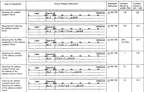
Figure 20 shows examples of address-constant-literal adjustment and of address-constant-literal address ad-justment. Assume that the equivalent addresses of the address-constant literal (+TAX or -TAX) and ADDR are 503 and 700, respectively, and that the address
con-stant of TAX is 123. (See Address-Constant Litera~ and
Address Constants Defined by a DCW Statement.)
Constant Operands
Constant operands are defined by area-definition
state-ments. See DC and DCW Statements. The assembler
assigns an area in core storage in which the constant is stored at object-program load time.
Input/Output Operands
For operations involving disk storage, write the mne-monic operation code in the operation field and the symbolic disk-address control field in the operand field. For example, the statement shown in Figure 21 will be
assembled M % F1 598 W if 598 is the equivalent
address of OUTPUT.
Figure 21. \Vrite Disk
For operations involving magnetic tape, write the mnemonic operation code in the operations field and the number of the tape unit in the operand field. The programmer can specify the number of the tape unit in one of three ways:
l. Write the actual address of the tape unit (% Ux) as
Type of Adjustment Source Program Instruction Assembled Constant Constant
Instruction Moved to Stored in
ADDR (700) 501 - 503
Adjusting the address
Label 15~perat~zl OPERAND -M 503 700 122 122
constant literal 6 25 SO S5 40 45
:
ML C 1+, • ,TAX - I • .A,D.D.R. IAdjusting and indexing
Label Operatian OPERAND M 503 700 IK2 IK2
the address constant 6 1516 20121 25 SO SS 40 45
literal
:
MoL C I+. •• T.A.X.-/+X.2 • . A.DD.R.I
Adjusting the 16,000's Label pperatian OPERAND M 503 700 H7H H7H
complement of the address 6 1516 20.21 25 SO S5 40 45 - (15,878)
constant literal I IML C - •• T.AX. - / • .A.D.D R
I
Adjusting the address,
label 15~perat~ 21 OPERAND -M 501 700 I 123
of the address constant 6 25 SO S5 40 45
literal
--'---'----'--' I IMLC +.TA.X.-2 A,D.D.I?
I
Ad j usti n9 the address
Label Operation OPERAND M 502 700 - 12 122
constant I iteral and 6 1516 20121 U SO S5 40 45
the address of the I
tvlLC + .. T.A,X - I • - I A.O,D.B.
address constant litera I I
I ndexi n9 the address label
15~perati:121 OPERAND -M 502700 IK IK3
constant literal and 6 25 SO S5 40 45
adj ust i n9 the address I IM,L.C. t .. T.A.l'. +.x2,. - I .A.D.D.R.
of the address constant I
literal
Figure 20. Address-Constant Literals with Adjustment and Indexing
I'
the A-operand. The statement shown in Figure 22 will be assembled M % U4 615 W if 615 is the equivalent address of OUTPUT.
~perati~ OPERAND
:~
:
label
Figure 22. Tape Instruction with Actual Address
2. Assign a label to the actual a"ddress of the tape unit, and use it as the A-operand of the tape instruction. (See EQU-Equate.)
3. Write the number of the tape unit in column 21 of the tape instruction. The assembled instruction for the statement shown in Figure 23 will cause a rec-ord to be written on tape-unit 4 using the data be-ginning in a storage area labeled OUTPUT.
label trati~
I I I 25 0
T ,OUTPUr:
~
40
OPERAND
:~ ~o
.
:Figure 23. Write Tape
For operations involving the 1443 printer, write W or WS in the operation field and the symbolic address
of the high-order position of the print-line in the operand field. For example, the statement shown in Figure 24 will be assembled: M % Y1 801 VV if 801 is the equivalent address of PRINTI.
I'
label ~o 40 OPERAND:5
~oFigure 24. Printer Operand
For operands involving the 1442 card read-punch, write the mnemonic operation code in the operation field. Then write the number of the. unit (lor 2), fol-lowed by a comma and the symbolic address of the high-order position of the I/O area. For example, M
% Gl 110 R will be the instruction assembled from the statement shown in Figure 25, if 110 is the equiva-lent address of INPUT.
label OPERAND
~o 40
:5
:
Figure 25. Reader Operand
[image:15.617.68.567.71.390.2]Statement Descri ptions
All Autocoder statements must be presented to the assembler program according to a special format. There are also rules and restrictions for writing the information in these statements. These requirements are necessary because the assembler needs and can handle only certain kinds of information from each type of Autocoder statement, and it must know where in the statement that information can be found.
In this publication the Autocoder statement descrip-tions are presented in a format that:
1. Describes the operation which the statement specifies.
2. Shows how the statement is written by the pro-grammer.
3. States the actions of the assembler during process-ing of the statement.
4. Describes the effect of the statement on the object program.
5. Shows an example of the statement.
Declarative Statements
Declarative statements are used to assign sections of storage for fixed data (constants) that will be needed during processing, to set aside work areas, and to assign symbolic names to data and devices used in the program.
The six declarative operations are:
Op Code Purpose
Dew Define Constant with Word Mark
DC Define Constant (No Word Mark)
DS Define Symbol
DSA • Define Symbol Address
DA Define Area
EQU Equate
DCW - Define Constant with Word Mark
General Description. Use a Dew statement to enter a
numeric, alphameric, blank, or address constant into core storage at object-program load time.
The programmer:
1. Writes DCW in the operation field. If more than one Dew statement is to be written in succession, the programmer needs to write the Dew operation code for the first DCW statement. The DCW operation
code for the remaining statements of the group can be omitted, if desired;
2. May write a label, but not an actual address, in the
16 Autocoder (on Disk) Language Specifications
label field. He can refer to the constant by using the label as an operand elsewhere in the program. If
the label starts in column 6, its equivalent address is the address of the low-order position of the con-stant in the object machine. If the label starts in
column 7, its equivalent address is equal to the high-order position of the constant in the object machine. 3. Writes the constant in the ope~and field beginning in column 21. A comma and a G immediately
fol-lowing the constant inserts a group-mark with a word-mark after the constant.
The assembler:
1. Allocates a field in core storage that will be used at object-program load time to store the actual con-stant.
2. Inserts the equivalent address of the label in the object program wherever the label is used as a symbolic operand in a source-progr-am statement.
Result: The constant with a high-order word mark is
loaded with the object program. Numeric Constants
A plus or minus sign may be written preceding an integer. ~ plus sign causes the assembler to store the constant with A- and B-bits over the units position; a minus sign stores a B-bit there. If the integer is un-signed, it will be stored as an unsigned field.
The first non-numeric column in the operand field indicates that the preceding position contains the last digit in the constant. •
A constant may be as large as 51 digits with a sign, or 52 digits with no sign.
Examples. Figures 26, 27, and 28 show the three types
of numeric constants that can be defined in DCW
statements. The labels TEN 1, TEN2, and TEN3 identify
the constants. Thus, they can be used as operands to cause the equivalent addresses of
+
10, -10, and 10 to be inserted in the object program whenever TEN1, TEN2, and TEN3 appear in operand fields of otherentries in the source program.
OPERAND
~o :; ~o
Figure 26. Numeric Constant with a Plus Value
Figure 27. Numeric Constant with a Minus Value
Figure 28. Unsigned Numeric Constant
Alphameric Consfanrs
Place an @ symbol before and after the constant. As
with alphameric literals, blanks and the @ symbol
may appear between these @ symbols, but the @
symbol must not appear in a comment in the same line as the constant.
Up to 50 valid characters can be written in an alpha-meric constant. Any combination of alphaalpha-meric characters can be used, with the following restric-tions:
1. If the object program is to be punched into cards
in the condensed-loader format, a word-separator character (0-5-8 punch) should not be the first
char-acter following the first of the two @ symbols
en-closing the constant.
2. If the object program is to be written on disk
(coreload format), a group mark should not be the
first character following the first of the two @ symbols
enclosing the constant.
A comma and a G following the alphameric constant cause the assembler to insert a group-mark with a word-mark after the constant.
Example: Figure 29 shows how to define the
alpha-meric constant, JANUARY 28, 1964 in a DCW
state-ment. The assembler will insert the equivalent address of the constant in the object-program
in-struction wherever DATE appears in the operand of
another source-program entry.
~
label~ 49
OPERAND
:~ ~9
I 64@ ATE
Figure 29. Alphameric Constant
Blank Constants
Blank constants used in DCW statements are equivalent
to area-defining literals in instructions.
Write the # symbol and an integer in the operand
field to indicate how many blank storage positions are needed in the area. The defined area can contain any number of blank positions.
Example: Figure 30 shows how to define an
II-posi-tion blank field using a DCW statement. The
equiv-alent address of the II-position field is inserted in
the object program wherever BLANK appears as an
operand in another source program statement.
~:el
~perati~ OPERAND~s 32 ~5 42 4~ :IQ
15~ [)CIA!
:t
11Figure 30. Blank Constant
Address Constants
A DCW statement can define the equivalent address of
an instruction, defined area, or constant.
Form C24-3258-1 Page Revised 6-1-65 By TNL N21-0038-0
In the operand field, write the label of the instruc-tion, area-definiinstruc-tion, or constant, and precede the label
with a plus or minus sign. If a minus sign is used,
the constant defined is the 16,000' s complement of the
equivalent address of the label. .
Example. Figure 31 shows how an address constant
(the equivalent address of MANNO) can be defined
by a DCW statement. The address of the equivalent
address of MANXO will be inserted into an
object-program instruction wherever SERIAL appears as the
operand of another source-program entry. Thus,
+MANNO is the symbolic address of the field that
contains the equivalent address of ~IAXXO.
OPERAND
4
Figure 31. Address Constant Defined by a DCW Statement
Address constants can be adjusted and indexed. The adjustment and indexing refer to the address constant itself rather than to the address of the
loca-tion of the address constant. If CASH is the symbolic
address of a field, the equivalent address of CASH is
indexed or address-adjusted rather than the
equiv-alent address of +CASH.
Example. In Figure 32 the address constant (the
equivalent address of CASH) is 600. \Vhenever TOTAL
appears as the operand of another source-program entry, it will represent the equivalent address of a location that contains 604 (the adjusted address
con-stant of CASH). (See Figure 20.)
Note: -CASH+4 would refer to position 15,404 ( 16,000-600+4).
I
label~OTAL ;
~
perati~
1516 21 ~ 30 35 42
OPERAND
45 52
Figure 32. Adjusted Address-Constant Defined by a DCW
Statement
DC - Define Constant (No Word Mark)
General Description: To load a constant without a
high-order word mark, write a DC statement. The
format of a DC statement is the same as that of a DCW
statement. The DC operation code is used in the
op-eration field. If more than one DC operation code is
to be written in succession, the programmer needs
to write the DC operation code for the first DC
state-ment. The DC operation code for the remaining
statements of the group can be omitted, if desired.
Example: Figure 33 shows TEN 1 defined as a constant
without a word mark.
I
lobe I~ENl
:35 49
OPERAND
45 ~9
~9
Figure 33. Constant Defined by a DC Statement
DS - Define Symbol
General Description. Use a DS statement to label and skip over an area of core storage. With a DS state-ment, the bypassed area is undisturbed during the loading process. Thus, any information that was in storage before loading begins will still be there after the object program has been loaded.
The programmer:
1. Writes DS in the operation field.
2. May write a label, but not an actual address, in the the label field.
3. Writes a number in the operand field that tells the assembler how many positions of storage to bypass.
The assembler:
1. Assigns an equivalent address to the label. This equivalent address refers to the low-order position of the bypassed area.
2. Inserts this address wherever the label appears as an operand in another source-program entry.
Result. The positions included in the bypassed area
remain undisturbed during object-program loading.
Exar[lple. Figure 34 shows how to direct the assembler
to bypass a IO-position core-storage area. Assume that the last core-storage position the assembler allo-cated before it encountered the DS statement was 940. The equivalent address of ACCUM is 950, the address of the low-order position of the core-storage area bypassed by the DS statement. Wherever ACCU\1 is used as an operand, 950 will be inserted in the object program.
~9 40
Figure 34. DS Statement
DSA - Define Symbol Address
General Description. The ability to code address
con-stants in Autocoder language eliminates the need fot the DSA statement except when the three-charac-ter machine address of "an actual address in the source program is desired. The address constants previously discussed were created from labels.
The programmer:
1. Writes DSA in the operation field. 18 Autocoder (on Disk) Language Specifications
2. May write as the label, the name that will be used to make reference to the address constant.
3. Writes the actual or symbolic address to be defined in the operand field. This address may be address-adjusted and indexed. DSA with a symbolic operand is equivalent to a DCW address constant.
The assembler:
1. Produces a constant containing the equivalent ad-dress of the storage adad-dress written in the operand field.
2. Assigns to this address constant an equivalent ad-dress in core storage and labels it using the name that appears in the label field.
Result. At program-load time the address constant
will be loaded into its assigned locations with a word mark in the high-order position.
Example. Figure 35 shows how to develop and store
an address constant for an actual address.
OPERAND
~9 40
:s
~9
Figure 35. Defining the Address Constant of an Actual Address
DA - Define Area
General Description. A DA entry reserves and defines portions of core storage. Use a DA entry to:
1. Define one area, such as an input, output, or work area.
2. Define several areas that have the same format. 3. Define fields within the defined area.
The complete DA entry has two parts: the DA header, which gives the assembler specific information on how to set up the area, and the subsequent DA statements, which define the fields within the area.
DA Header
The programmer:
1. Writes DA in the operation field.
2. Writes a label. The equivalent address of the label represents the high-order position of the entire area defined by the DA header statement.
3. Writes the first operand in the form B X L. B is the number of identical areas to be defined and L is the length of each area.
4. May write a comma and the number of an index location (Xl, X2, or X3) after the B X L entry. The indexing specified in the DA header statement refers
to subsequent DA entries. Tag bits will be over the
tens position of the equivalent addresses wherever the labels of subsequent DA entries appear as
oper-ands in source-program instructions, unless the operand is indexed. The indexing in the operand
overrides the indexing specified by the DA header. Note: Symbolic indexing is not permitted in a DA header statement.
S. May write ,9= after the B X L entry to cause the assembler to insert a record mark without a word mark immediately after each area defined by the
B X L entry.
6. May write ,G after the B X L entry to cause the assembler to insert a group-mark with a word-mark immediately after the last area defined by the B
X L entry.
7. May write ,C to cause the assembler to clear the defined area(s) at object time before any word marks are set.
Note: The ,9=,G,C and, index-code entries may
be written in any order after the B X L entry.
Subsequent DA Entries
The programmer:
1. Leaves the operation field blank.
2. May write a label. The equivalent address of the label represents the low-order position of the field or subfield with which it is associated. A subfield is a field within a defined area or field.
3. Specifies in the operand field the relativ~ location of a field or subfield. The first position of each area defined by the DA header statement is
con-sidered location 1.
a. To define a field, write the high-order and low-order position of the field (beginning in column 21). Separate the two numbers by a comma. To define a one-position field, write the relative location number twice. \Vord. marks are set in the high-order positions of all defined fields.
b. To specify the location of a subfield, write the number (beginning in column 21) that represents the relative location of the low-order position of the subfield. The location is rdative to the first position of the area de-fined by the DA header statement. No word marks are
set in the low-order positions of subfields.
A subfield can be located anywhere within the area defined in the DA header statement. It does not have
to be within a field defined by a subsequent DA entry.
4. May list fields and subfields in any order after the
DA header statement. All the fields within the area
need not be defined.
The assembler:
1. Allocates an area which is equal in length to the total of B X L plus positions for record marks and a group-mark with a word-mark, if they have been specified in the DA header.
2. Assigns equivalent addresses to the DA header label
and to the labels of all defined fields and subfields.
3. Inserts the equivalent address of the high-order position of the entire defined area wherever the label of the DA header appears as an operand in the
program.
4. Inserts the equivalent addresses of the low-order positions of fields and subfields defined in the other
DA entries wherever their labels appear as operands
in the pro grain.
Result. When the object program is loaded:
1. The entire defined area is cleared if the DA header
statement contained a comma C.
2. Word marks are set in the high-order position of all fields defined by subsequent DA entries. A word
mark is set in the high-order position of each area defined by the DA header if a subsequent DA entry is I,n.
3. A group-mark with word-mark, and record marks are set if they have been specified by the DA header. Example. Figure 36 shows a DA header statement that defines four IOO-position areas. If only one area is to be defined, write 1 X 100 as the first entry in the operand field.
~ Label ~peroti~ OPERAND
~Q ~~ 4Q 41 ~
:~e.E.A.B
'~~ ~,u~
Figure 36. DA Header
Example. INAREA is defined by the DA header shown in Figure 37. The second statement in Figure 37 defines a field within INAREA. Thu" the equivalent address of ACCUM has a tag bit (A-bit) over the tens position to indicate that it is to be indexed by the contents of index-location 1.
, 15 I I 31t 35 40 45 Q
~
l.bo,r'."~
OPERAND~~~Ai
: : :
=~
:
]~::£;X:J
: :
~
: : : : : : : : : -: : : : : : : : : :
Figure 37. Indexing a DA Entry
indexing, the assembler will tag the equivalent ad-dress of ACCUM with a B-bit when it assembles the instruction for that statement. The indexing in the statement that uses ACCUM as an operand overrides the indexing prescribed by the DA header statement.
Label OPERAND
[image:20.613.53.547.485.727.2]40
Figure 38. Overridil}g Previously Prescribed Indexing
To negate the effect of indexing on a field or sub-field, put an XO in the operand field of each instruc-tion in which indexing is not wanted (Figure 39).
Label OPERAND
40
:~
~
Figure 39. Negating the Effect of Indexing
Example. Figure 40 shows a DA header statement that
directs the assembler to insert a record mark after each of the areas defined and a group-mark with word-mark immedia:tely after the last-defined area. The 2 X 100 entry causes 200 positions to be re-. served by the assemblerre-. The ,9= and ,G entries
cause 3 additional positions to be reserved as shown in Figure 41.
b
Label 151 ~perati~ I 2 a 49 OPERANDuTA. :
Figure 40. DA Header
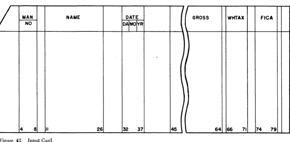
MAN NAME DATE
NO
°1
MO/ VR
4 8 II 26 32 37
Figure 42. Input Card
20 Autocoder (on Disk) Language Specifications
I
i00i .. 1 - - - -203 Positions ---~·I
11ooII . . f---l00 Positions
--J
I.--
100 Positions--J
Figure .41. Record Marks and a Group-Mark with aWord-Mark
Example. A payroll record (Figure 42) is to be moved into an area of core storage.
The card record is 80 positions, one for each column of the card. The significant fields to be de-fined in the record area are:
Positions Label Description
4-8 MANNO Man Number
11-26 NAME Employee Name
32-37 DATE Date
45-64 GROSS Gross Wages
66-71 WHTAX Withholding Tax
74-79 FICA FICA Deduction
The remaining card columns contain data not needed for the operation. Positions 34 and 35, which indicate the month within the date, will be defined as a subfield. A group-mark with a word-mark is needed in the storage position immediately follow-ing the area.
The DA header shown in Figure 43 defines the area
into which the record is to be moved. The 1 X 80 entry causes the assembler to reserve 80 core-storage
I
GROSS WHTAX FICA
I
J
,
I
45 64 66 71 74 79
positions for the area. The ,G causes the assembler to set a group-mark with a word-mark in the 81st position of the area at program-load time. This area can then be referred to by using the name RDAREA in the operand of another source-program entry. The equivalent address of RDAREA will be the 3-character machine address of the high-order posi-tion of the entire area allocated by the assembler. The other DA entries shown in Figure 43 define the fields and subfields within the record.
Figure 43. DA Entry
In the source program, an instruction to move the record into a storage area labeled RDAREA will cause the data in the record to be stored in the appropriate fields. Source-program statements may then be written to manipulate this data, using the labels as operands. The word marks set at program-load time will stop the transfer of data when indi-vidual fields are moved, added, etc.
EQU - Equate
General Description: Use an EQU statement to assign
a label to an actual, asterisk, or symbolic address,
or to a control field or ~n index location. More than
one label can be assigned to represent the same storage location.
The programmer:
1. Writes EQU in the operation field.
2. Writes a label.
3. Writes an actual, asterisk, or symbolic address in the operand field.
Note: Xl, X2, and X3 should not be used as labels of EQU
statements, because the assembler assumes that they are equated to 089, 094, and 099, respectively. Further, a label must not be equated to a literal, because the assembler considers such a label as being undefined.
The assembler:
1. Assigns to the label of