2016 Joint International Conference on Artificial Intelligence and Computer Engineering (AICE 2016) and International Conference on Network and Communication Security (NCS 2016)
ISBN: 978-1-60595-362-5
Multi-level Framework Development of Distributed Underwater
Detection System Based on UML Modeling
Bo LI
1,a, Jing SUN
2,b, Xiang-Wen LENG
1,c1Dalian Naval Academy, Dalian 116018, China
2Military Real Estate Bureau of Dalian, Dalian 116021, China
a[email protected], b[email protected], c[email protected]
Keywords: Underwater Detection System, Framework, Distribution, Layering.
Abstract. Aiming at the distributed structure of the new-type underwater detection system, the paper proposes a development method of underwater detection system based on UML, constructs information type and subsystem by analyzing static structure and dynamic behaviors of the system, realizes the analysis modeling of distributed underwater detection system, proposes layering software framework structure, and enhances system maintainability and reusability. The framework structure is equipped with the characteristics of distribution, modularization and reconfigurability.
Introduction
Underwater detection system has a broad application prospect in marine environment detection and underwater target identification. With the constant improvement of system performance requirements, the system complexity is increasingly high. The traditional centralized control model has already limited the improvement of system expansion and compatibility. The framework structure of current underwater detection system tends to have the distributed structure with good expansibility and universality. Changes of system framework structure need to have coordination from the corresponding system development mode. The traditional underwater detection system adopts the design mode from the top to bottom and gradually completes software design, strong exclusiveness of software, and bad transportability by aiming at specific design demands. The adoption of dividing and ruling the modularization layering design model not only can reduce system complexity, but also can improve system development efficiency, and increase maintainability and expansibility[1].
System Analysis
Underwater detection system is composed of multi-node modules, while node module is composed of one or multiple functional elements, which can be divided into basic function and extended function. The basic function means that underwater detection system must be equipped with detection, identification, positioning, and system control, etc., functions. Extended function means that detection system increases decreases functions in line with specific datable system.
According to features of underwater detection system, the basic functions can be defined as follows:
1. Recognition function of underwater integrated survey—underwater detection system can realize simultaneous measurement of several kinds of underwater physical quantity, distinguish detected objects, and obtain motion laws of objects;
2. Self-inspection, self-correcting and self-control functions—underwater detection system has been kept in the underwater working state for a long time. The system realizes self-control functions in line with setting procedures in advance. The system can conduct self-inspection when connecting to power supply. Diagnostic test is used for ensuring whether module components have or have not faults. In working process of the system, the system can realize online correction of characteristic data quantity for inner storage by aiming at conversion of external physical quantity.
3. Data storage and transmit system—the system can realize storage of detection data, realize data transmit through the remote-control transmitter-receiver set, and receive corresponding functions, such as dormant system and system work, etc.
4. System expansion function—the system can realize expansion of basic functions for underwater detection system or performance improvement by aiming at different detection demands, such as remote sensing, feature recognition and gesture measuring, etc.
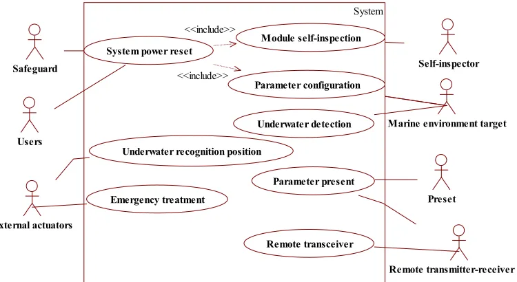
According to the functional analysis of the system, it can confirm behaviors and related use cases of the system. The Fig. 1 describes use cases and behaviors, as well as the associations between use cases and use cases.
System Frame Design
Establishment of Subsystem
To determine by use case, the designer can determine the participating object of each use case and find the relationship between objects from the interaction between objects. If there is interaction between the two objects, then there will be a link. The collaboration diagram of UML is to achieve the description of the dynamic interaction relationship between objects by sending or receiving information between objects and analyze the behavior of the objects, thus, it can identify the attributes and behaviors of the objects. This article focuses on the extraction of the class and the correlation between classes, so there is no need to unfold the analysis collaboration diagram.
By object interaction model of the use case to form the basic subsystems, objects of the subsystems are associated. Objects communicate with each other, so the degree of coupling between them is higher. While the degree of coupling of they with the objects in other collaboration diagram is relatively lower, even no. If an object is involved in several use cases, it should be assigned into the subsystem which has the highest degree of coupling with it. If the subsystem is from several collaboration diagrams and use cases, and at the same time these collaboration diagrams and use cases have correlative dependence from all the functions and share a common object. Then the subsystem may contain multiple objects from multiple collaboration diagrams[6].
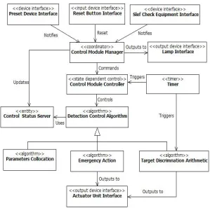
subsystem. Starting from the collaboration diagram to develop the class diagram of solution domain, object mapping on the collaboration diagrams can instantiate their classes. The connections between the objects on the collaboration diagrams have a corresponding relationship on the class diagrams. Fig. 2 and Fig. 3 are respectively the static model of control module subsystem and sensor module subsystem. The relationships between classes are most the incidence relation and there only exists the generalization relationship in some classes which are shared and having public characteristics. In control module subsystem, the identified control classes are the other class of algorithms: class of algorithms of parameter configuration and the superclass of class of algorithms of target comprehensive identification. In the sensor module subsystem, class of algorithms of detection is class of algorithms of model self-calibration, class of algorithms of zero point detection and the superclass of class of algorithms of target detection and identification.
System
Underwater recognition position Users
Parameter present Safeguard
Remote transmitter-receiver set External actuators
Module self-inspection
Underwater detection
Remote transceiver
Marine environment target Self-inspector
Preset System power reset
Parameter configuration
Emergency treatment
<<include>>
[image:3.612.120.495.219.424.2]<<include>>
[image:3.612.138.477.471.715.2]Figure 1. Use Case Model Diagram of Underwater Detection System.
Figure 3. Subsystem Class Diagram of Sensor Modules.
Design of Class
In accordance with the principle of object-oriented design, according to the system characteristic and the demand analysis for underwater detection system, the typical underwater detection system can abstract out as the following core classes:
(1) Device interface class: Each I/O devices has a corresponding device interface class and it always in the device interface tasks or the tasks determined based on the clustering criterion and it encapsulates the operations of initialization, read, etc.
(2) Data abstraction class: To encapsulate the data structures of the measured objects underwater, including the semaphore and state parameter of each physical field signal and so on. The abstract class hides the presentation details of internal data structure.
(3) State of control class: In the control module, there is the state of control class of control module. In the sensor module, there is the state of control class of sensor module. Each contains control state machine of its own module. It provides two operations: operation of event processing and operation of getting the current state.
(4)Business logic class: It is in control module and has the logic task of emergency processing. It processes the related request of the control module. It is possible to realize the of emergency state transition of the system and failure process.
(5) Algorithm hidden class: algorithm class is used to encapsulate different algorithms. The algorithm is usually relatively independent and the different system organization may bring out the different algorithm object. Using algorithm classes to encapsulate different kinds of algorithms can achieve inheritance of system software design well and increase the general design of the system. Software Architecture Modeling
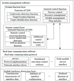
describe the advanced properties of the complex system and simplify the complexity of software system. It is not only convenient for software reuse but also convenient for the expansion and upgrade of the system[7]. To combine with the object-oriented analysis of underwater detection system, the whole software structure is divided into four layers: system function layer, system control layer, real-time communication software and hardware module abstraction layer, as shown in Fig. 4. The system function layer and system control layer can be called as underwater detection system management software and they locate in the application layer. Among the layers, to do information interaction through a standard interface so that to ensure the independence of each layer. System functional layer provides general management and control function of the system. It is responsible for scheduling and management of internal function modules to realize the basic function of target detection, identification, location of underwater detection system. The control of system function layer to underwater detection system belongs to the control of general logic level and does not involve involve the specific characteristics of system model. The specific control to special underwater detection system is achieved by transferring the system control layer. System function layer is through the system control interface and system control layer to perform the information exchange.
Figure 4. Distributed Software Structure of Underwater Detection System.
Framework Implementation
Because the detection of physical fields type, working condition and other performance indexes of underwater detection system are preset, the system will be a independent work condition for a long time after laying.
Figure 5. Module Hardware Interface.
Figure 6. Internal Structure Model of Node Modules.
[image:6.612.211.415.370.605.2]This is the independent and intelligent characteristics of modules in the underwater detection system. Through the implementation of functions, modules in the system can realize "plug and play" function. For ease of needs of system debugging and expansion, the hardware circuit of node module uses the design which a core board separated from an interface board, the core board is mainly made up of the functional circuit of node modules, and the hardware interface circuit in the system is designed in the interface board, two pieces of circuit boards connect with each other by the expansion slot. Therefore, the interface board normally does not need to modify. The core board can modify hardware resources according to the different module functions. Fig. 5 module hardware interface scheme.
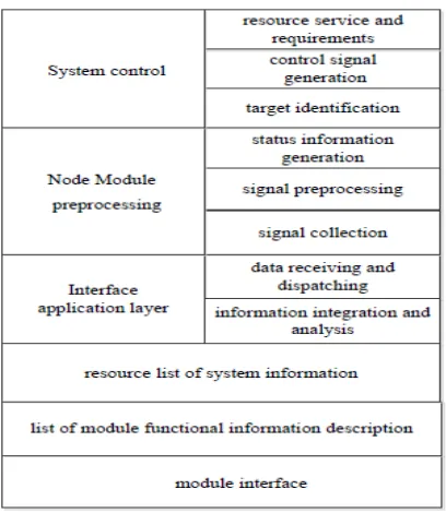
For resource list which implement and maintain the system in modules, Fig. 6 shows the basic interface of node module and internal implementation which designs an information layer between the internal functional entities of the interface and modules, which includes two aspects of content: One is the list of functional information description of the node, which is available for other nodes to call a query; Two is a copy for the resource list maintained by system, which realizes this node's grasp of the internal conditions in the whole system.
The executing process of the system program and responsibility of each node module has been planned in advance before the system integration. According to the different stages of performing tasks, the node module at the appropriate time will participate in and exit the executing process of a task. As underwater detection system is a small system which has relatively clear and fixed tasks as well as complex tasks, in a distributed control mode, when the node module has the certain independence and intelligence, the realization of interconnection in node modules through task driving mode to will ensure the well operation of system.
Conclusion
On the basis of presented functional requirements of underwater detection system and systematic characteristics of the distributed structure, this paper uses the modeling method based on UML to build the underwater detection system and designs the hierarchical software structure. The prototype experiment shows the system works well and the method is suitable for the development of the underwater detection system, which can improve the maintainability and reusability of the system.
References
[1]Li Bo, Zhou Suihua. Internal bus system design of underwater detection system [J]. Chinese Journal of Scientific Instrument, 2008, 29 (8): 30~34.
[2]Wu Ji, Jin Maozhong. UML Object-oriented analysis [M]. Beihang University Press, 2002.3: 2~6. [3]Booch G., Rumbaugh J., Jacobson I. The Unified Modeling Language User Guide [M]. Addison Wesley Longman, 1999: Appendix B.
[4]Kim Y.G., Hong H.S., Bae D.H. Test Cases Generation from UML State Diagrams [J]. IEEE Proceeding on Software,1999, 146(4): 187-192.
[5]Abdurazik A., Offutt J. Using UML collaboration diagrams for static checking and test generation [J]. York, UK, 2000, 383-395.
[6]Ji Zhen Yan. UML System analysis design and application cases [M]. People's Posts and Telecommunications Press, 2003.5: 2~10.
[7]Wang Jianxin, Yao Fangwu. The hardware and software collaborative design methods based on UML [J]. Computer technology and development, 2006 (1): 96-98.
[8]Hassan Gomaa. Designing Concurrent, Distributed, and Real-Time Applications with UML [M]. Pearson Education, Inc. 2000.