© 2017, IRJET | Impact Factor value: | ISO 9001:2008 Certified Journal | Page 1873
Design & Development of Hydraulic Valve Testing machine
Prof. Sanjay. D. Kulal
1, Mr. V. P. Gaikwad
2,Mr. D. B. Ghadage
3, Mr. P. F. Hajare
4.
1
Assistant Professor, Department of Mechanical Engineering, Fabtech Technical campus, Sangola, Maharashtra.
2, 3, 4 U. G. Student, Department of Mechanical Engineering, Fabtech Technical campus Sangola, Maharashtra.
---***---Abstract—Today’s safety engineers face increasing challengesevery day. Safety requirements are becoming more and more challenging, while the overall market situation is simultaneously creating constant pressure to reduce costs. For these reasons, safety engineers need to reassess the safety-loop testing techniques at their plants. Manufactured from castings they may not look very sophisticated, but in their design, accuracy and function they resemble a delicate instrument whilst performing an essential role. The main purpose of safety valve testing is to prove safety valve availability.
Key Words: hydrostatic, pneumatic testing, Moving Plate etc.
1. INTRODUCTION
The purpose of hydrostatic testing a pipeline is to either reduce any defect that might threaten its ability to sustain its maximum operating pressure or to show that none exists. A important word here is pressure. Hydrostatic testing consists of floating the pressure level above the operating pressure to see whether or not any defects with failure pressures above the operating pressure exist. If defects fail and are eliminated or if no failure occurs because no such defect exists, a safe margin of pressure above the operating pressure is demonstrated
1.1 Advantages of hydro testing-
Hydrostatic Testing is a process where components, such as piping or pressure vessels are tested for strength and leaks by being filled with pressurized liquid. For pipelines, the pipeline is removed from service before testing. All oil and/or natural gas are then vented off and the line is mechanically cleaned.
Advantages:-
1. Hydrotesting satisfies the quality of valve / centrifugal pump/ pipeline.
2. Hydrotesting minimizes the risk of damage. 3. Hydrotesting ensures the leak free plant pipeline. 4. Test pressure normally 30 % above the test pressure normally 10 % above the Design pressure.
5. Energy stored per unit volume of water under pressure is very negligible.
6. Recommended to prove the strength of equipment. 7. Chances of equipment failures are less.
8. Test media can be reused and transferred to other place after testing.
9. Skilled and semi-skilled personnel can carry out test.
10. Recommended where large volumes are to be one tested at same time (example pipe lines).
11. Damages due to failures are less compared to failures in pneumatic testing.
1.2 Limitations of hydro
testing-1. Needs thorough cleaning after test to ƒ eliminate moisture especially for service which is reactive to moisture / fluids. 2. Normally water is used as medium of test.
3. Pressure Relief valves are recommended to control sudden increase in pressure during testing.
4. Needs less safety distance to cordon off from man entry during test period.
5. Weight of equipment with test medium as water is high hence special attention should be given to floor and supporting arrangements.6
6. Needs verification and examination of joints and connections before testing.
2. DESIGN OF SYSTEM
2.1 Calculating load capacity of piston rod
In our case the pressure is applied by on one face of the piston while the other cross section of the piston faces the fixed wall. This means that the failure or breakage of piston rod will occur only due to excessive compressive stress developed in the piston rod.
As we know that the maximum limit of compressive stress that a mild steel specimen can bear is 407.7 Mpa. Since the diameter of the piston is 15 mm therefore we can lastly calculate the amount of maximum load which can be beard by the piston.
F
A
Where.,
R = radius of the piston rod, σ = stress,
A = area of the piston head. But, A = πR2
Area
2
4
A
© 2017, IRJET | Impact Factor value: | ISO 9001:2008 Certified Journal | Page 1874
2407.9
/
Stress
N mm
Force
stress
Area
407.7 176.71
72046
N
We know,
1
Kg force
9.81
N
( )
72046
9.81
Force F
7344
F
Kg
Also we know,
1
Tone
1000
F
7.3
Tones
This means that 7.3 tones are that 7.3 tones is the last limit of our piston rod. But our aim is to design the hydraulic cylinder which can easily with stand with 3 to 5 tones.
2.2Calculating the maximum inside pressure of
barrel
Let’s assume a weight of 1.5 tones acts on the piston. Therefore the pressure created by the piston in the cylinder or barrel can be calculated by the following formulae.
Force
Pressure
Area
Where area is the cross section of the piston rod.
2
4
D
Area
2
1
76.71
mm
Force
Pressure
Area
Force
5
tones
We know,
1
ton
1000
kg
1500
Force
kg
Again, we know
1
kg force
9.81
N
Force
9.81
1500
N
9.81 1500
176.71
Pressure
2
100 /
Pressure
N mm
Let’s say Pressure = 100 N/mm2
This means that pressure of 100 Mpa or 100N/mm2 walls of the cylinder barrel when the hydraulic
cylinder will load with 5 tones force.
2.3 Calculating the thickness of the barrel
The lame's equations are:-
2
b
a
r
c
2
b
a
r
Where,r c
The radial stress
The circumferential stress
a and b
constants
r
radius
Since the internal diameter meter of the barrel is 40 mm as per design. Now we have to calculate the outer diameter of the barrel.
Inner 1
40 20
2
Di
radius
r
mm
Let outer radius = 80 mm,
Since the material used for making cylinder barrel is mild steel SA 36 there maximum tensile stress for this material is 410 Mpa
i.e.
σc at inner radius (ri) equal to 410 Mpa
2410 =
20
cb
a
2410
20
b
a
--- (1) Also,
2r i
b
a
r
Since pressure at inner surface is 100 Mpa σr at inner radius
is equal to100 N/mm2
2
1
00
20
a
b
σr at inner radius is equal to 100 N/mm2
2100
20
a
b
---(2)© 2017, IRJET | Impact Factor value: | ISO 9001:2008 Certified Journal | Page 1875
1
b
02, 000
N
Put the value of b in Equation 2 & we get
a
1
55
N/mm2Therefore, Lame's equation for our case become
102000
21
15
c
r
And,
r
102000
21
15
r
Now the barrel was must be strong enough to absorb all the stress such that the stress at the outer surface of the barrel must be zero.
i.e.
r
at radius r
o
r
102000
21
15
r
21
02000
r
1
15 0
o
r
2
1
02000
115
or
2886.956
o
r
29.78
r
o
mm
30
r
o
mm
o30 2 60
Outer diameter d
mm
-
Barrel wall thickness t
Outer radius Inner radius
– 30 20 1 0
t
r
or
i
mm
2.3 Base Design
The base should be design with such specifications so that it can easily with stand with the maximum pressure exerted by the vertical hydraulic cylinder. The force exerted by the horizontal cylinder should be less than tones as per our design considerations sour aim is to find the thickness of the channel used to design the base
2.4 Calculating length of vertical cylinder
In vertical cylinder will be decided from the stock required from this cylinder. It is practically seen that even a gap of 20 or 30 mm clearance is required at the top of piston. So the vertical cylinder is about 100 to 120 mm is enough for the operation of hydrous. The length of vertical cylinder equals to the sum of the end wall thickness, oil gap, piston thickness, stock bush thickness and thickness of the seal i.e.
L
V
t
1
t
2
t
3
t
4Stock
Where,
1 2 3 4
t
thickness of the end cap
t
thickness of the bush
t
thickness of the cylinder head
t
thickness of the top tap inside the cylinder head
L
V5
15
15
10
55
100
mm
[image:3.595.315.554.429.595.2]3. EXPERIMENTAL SETUP
© 2017, IRJET | Impact Factor value: | ISO 9001:2008 Certified Journal | Page 1876
Photo.3.1Actual setup
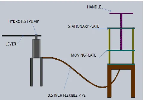
In the proposed test set up we have arranged the whole assembly as shown in fig. In which we have implemented machine vice principle. In the proposed arrangement there are two types of pressure plates are there, in which one is stationary and another is moving. The 2nd
pressure plate we are going to move by using screw.
Fig.-3.2 Arrangement of Setup
4. HYDROSTATIC TESTING PROCEDURES
A. Each valve shall be tested on both sides at its rated pressure. During the hydrostatic test, there shall be no leakage through the valve body, end joints, or shaft seals, nor shall any part of the valve be permanently deformed.
B. The testing medium shall be water. Under no circumstances is a gas to be used as the Test medium.
C. The test duration on each side of the valve is 15 minutes. The test equipment will be disconnecting during this time.
D. Valves require careful handling when turning them over. The district representative shall stop the testing activity if the manner used by the tester to handle the valves is unsafe or will result in damage to the valve. The flange faces are especially susceptible to damage if the valve is not properly handled.
E. Valves exhibiting no visible leakage, no decrease in the initial test pressure or no deformation shall be considered passed.
F. Valves exhibiting visible leakage, a decrease in the initial test pressure, or deformation shall be considered rejected. Valves which fail the hydrostatic test shall be repaired or replaced at the district’s discretion.
G. Only personnel authorized by the valve manufacturer shall repair valves when repairs are permitted by the District Engineer. Unless the valve manufacturer has provided authorization, supplier or contractor personnel shall not perform repairs.
H. Indicate the results of the hydrostatic test on the Valve Test Sheet (Exhibit A).
4. TESTING & DISCUSSION
To test and confirm the working of developed mechanism for Hydro testing machine, we have taken practical demonstration at workshop. Also we have collected the feedbacks and improvements points in developed model.
Actual Observation testing on machine
Valve type considered = Non return valve Size:-50mm
Flange Standard:-IS1538 Testing Standard:- API 598
© 2017, IRJET | Impact Factor value: | ISO 9001:2008 Certified Journal | Page 1877
5. CONCLUSION
At the end of this project the concluded remark is, the apparatus HYDROTESTING MACHINE is very useful for industrial purpose for hydro testing application
The main outputs and conclusions remarks are as below;-
1. Hydro testing machine operates successfully and It meets the all parameters of test rig as per ISO/ IS / API standards for valve / centrifugal pump/ pipeline.
2. Hydrostatic test is safer as compared to Pneumatic Test, It is observed that Water or liquid used for pressure test are not compressible compared to air or gases. Energy stored is very less. Small leak will reduce gauge pressure immediately which does not happen when Air is the test medium. It has less potential energy hence damages are mostly limited to nearby area. There is a possibility that you can take remedial action once minor leakages are noticed before total failure occurs. Leakages are easy to detect in case of hydrostatic test
3. Test time required minimized and standard procedure adopted for testing.
4. Chances of equipment failures are less.
5. Test media can be reused and transferred to other place after testing.
6. Skilled and semi-skilled personnel can carry out test.
REFERENCES
[1] William Rahmeyer “Dynamic flow testing of check valves” Nuclear Industry Check valve Group, 1996 Winter Meeting, St. Petersburg, Florida.
[2] Electronic Valve Tester-EVT-Pro
[3] VELAN “Cast steel valves gate, Globe, and check”, ASME CLSSES 150-1500 NPS 2-64(DN 50-1600) API600/API594/ASME B16.34
[4] Valve Inspection & Testing (API 598)
[5] Mr. R. S. Khurmi & J. K. Gupta” Machine Design” , Eurasia Publishing House Pvt. Limited
Sr.
No observed Points
Existing manual method
New developed method mechanism
1. requirement Labour
02 LABOUR 02 = Unskilled
labor
01 LABOUR 01 Unskilled
labor
2. required Time Totally depends on manual experience
Less than manual method
3. required Space
Storage space for flanges and nut – bolts are required
Storage space required for
machine.
4.
Electricity required for
mechanism or accessories
Not required Not required
5. handling Material More than developed mechanism
Material handling is very
less. 6. Manual effort More required Very less required
7. Maintenance
15Rs per person hospitality
charges
Maintenance cost considered 10% annually of
total cost
8. consumption Water Totally depends on human tendency.
Less water consumption
due to standardization