© 2017, IRJET | Impact Factor value: 5.181 | ISO 9001:2008 Certified Journal | Page 1351
Bracings as Lateral Load Resisting Structural System
Pooja Desai
1, Vikhyat Katti
21
Pooja Desai, Dept. of civil Engineering, Gogte Institute of Technology, Belgavi, Karnataka, India
2Asst. Prof. Vikhyat Katti, Dept. of civil Engineering, Gogte Institute of Technology, Belgavi, Karnataka, India
---***---Abstract –
Bracings are the most common lateral load resisting systems. They are widely used in earthquake prone areas to enhance the seismic response of structure. In this paper Behavior of concrete and steel X braces with varying storey height is investigated. This paper summarizes the seismic behavior of four structures with 5, 10, 15 and 20 storey’s and plan dimension of 25m x 15m. These structures are analyzed using equivalent static load method and response spectrum method in ETABS. Parameters such as base shear, displacement and natural time period were compared and presented in form of graph. It was observed that on adding bracings the seismic response of the structure was improved.Key Words: X braces, Equivalent static load, Response spectrum, Displacement, Stiffness.
1. INTRODUCTION
The main aim of all kinds of structural system in a building is to transfer the gravity load effectively and thus assure safety of the structure. Apart from these vertical loads, structure is also subjected to lateral loads which can develop high stress which will cause, sway of the structure. Buildings are usually subjected to different types of loads i.e. Lateral load due to wind and earthquake and vertical loads due to gravity (Dead + Live load on the structure). So the structure should be such that it should be strong enough which can resist all types of loads. When structures are subjected to lateral loads especially tall structures, these structures show large displacement and to reduce this displacement and drift moment resisting frames along with different types of lateral load resisting structural forms are available. Among them braces and shear walls is the most common lateral load resisting systems. In areas subjected to earthquakes, reinforced concrete structures having tall heights cannot bear large displacements. To resist the drifts and large displacements in buildings which may damage the buildings and cause loss of life, can be reduced to a large extent by using bracing systems. The present work focuses on finding the suitable bracing configuration that will adequately reduce the response of the structure to seismic excitation.
1.1
Objectives
Following are the objectives of the present study:
To study and compare the seismic response parameters (base shear, drift, etc) RCC frame building of multi-storey (5-, 10-, 15-, 20-stories)
with and without braces by Equivalent Static analysis and Response Spectrum analysis.
To investigate the seismic response of a multi story RCC frame buildings by providing X-braces at different locations within the buildings.
To suggest the most preferable location of X-braces for building of different heights based on the optimum seismic response of the building.
1.2 Bracing system
Braced frame system in the structure consists of truss members as bracing elements. These bracings are commonly used in structures, subjected to lateral loads. They resist lateral forces mainly with the brace members in compression or tension. This makes the bracing system highly efficient in resisting the lateral loads. Also, another reason for the braced frame system to be efficient is, it makes the structure laterally stiff. With least addition of the material to the frame and it forms economical structure for any heights.
Types of Bracings
Based on the types of braces employed in this study, bracing systems are classified depending on whether the braces are connected at column beam joint or away from column beam joint. Braces are grouped into various categories as follows
I. Based on the material used in braces-
a) RCC brace: These are the braces which are made up of reinforced cement concrete. The Cross section of concrete brace is similar to RCC beam or column section. These types of braces are strong in compression but are rarely used because of their construction difficulties and also another disadvantage is, these braces cannot be replaced once damaged due to seismic loads and hence it becomes uneconomical.
© 2017, IRJET | Impact Factor value: 5.181 | ISO 9001:2008 Certified Journal | Page 1352 II. Based on the way braces are connected to the
frame-
a)
Concentric: In a concentrically braced frame bracing members are connected to beam or column junction. Different types of concentric braces can be further classified depending on their configuration. Examples for concentric braces are V type, X type, K type etc.b) Eccentric: In an eccentrically braced frame bracing members are connected to separate points on the beam or column. The segment or link present between beam members help in absorbing energy from seismic activity*through plastic deformation. Eccentric Bracings improve the lateral stiffness and increase the energy dissipation capacity. In eccentric connection of the braces to beams, the lateral stiffness of the frame depends upon the flexural stiffness.
III. Based on the braces configuration-
a) V brace: Bracing*where a pair*of braces joins*at a single point*on the beam*span. Inverted*V brace- is*that form*of chevron bracing that*terminates at point on beam from below.
b) X brace: Bracing where two diagonal braces crosses near mid-length of the bracing members.
c) K brace: Bracing where a pair of braces connected on one side of a column joins at a single point on another leg of column.
2. DESIGN PARAMETERS
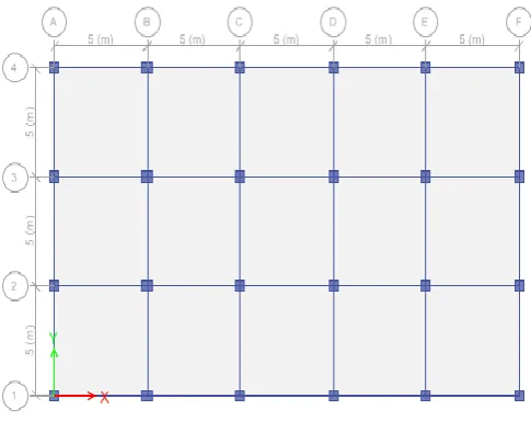
1. Type of building: Multi Storied Building. 2. Zones: V.
3. Type of soil: Medium soil. 4. Plan of the Building: 25mX15m. 5. Each Bay Size: 5m.
6. Number of Stories: 20 7. Floor to floor height: 3.5mts. 8. Live load: 3kN/m2
11. Slab Thickness: 0.125m. 12. Steel Brace: ISHB 150.
13. Concrete Brace: 0.230m X 0.230m 14. Materials: M35 and Fe500.
[image:2.595.307.558.123.414.2]14. Seismic analysis: Response Spectrum Method as per IS: 1893 (Part 1):2002.
Table 1: Beam and Column dimensions.
Storey Floors
Total
Height
(m)
Beam size
(mm)
Column size
(mm)
5 1st to 5th 17.5 230x450 450x450
10 1st to 5th
35
230x750 500x500
6th to 10th 230x525 450x450
15 1st to 5th
52.5
230X850 600X600
6th to 10th 230X800 500X500
11th to 15th 230X550 450X450
20 1st to 5th
70
230X850 650X650
6th to 10th 230X800 550X550
11th to 15th 230X700 500X500
16th to 20th 230X450 450X450
2.1 CASE OF STUDY
[image:2.595.312.555.481.673.2]Case 1: Bare frame with walls Case 2: Bracings in side bay Case3: Bracings in interior bays
© 2017, IRJET | Impact Factor value: 5.181 | ISO 9001:2008 Certified Journal | Page 1353 Fig -2: Frame with walls element (Case 1)
Fig -2: Frame with wall element and bracings at corner bays (Case 2)
Fig -3: Frame with wall element and bracings in interior bays (Case 3)
[image:3.595.316.554.174.503.2]3. RESULTS
Table 2: Values of natural time period(concrete bracings)
Case
Storey 1 2 3
5 0.142 0.138 0.135
10 0.274 0.272 0.268
15 0.406 0.397 0.388
20
0.536 0.524 0.536
Fig -4: Variation of Natural Time Period (concrete bracings)
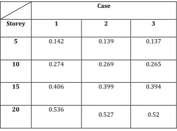
Table 3: Values of Natural Time Period(steel bracings)
Case
Storey 1 2 3
5 0.142 0.139 0.137
10 0.274 0.269 0.265
15 0.406 0.399 0.394
20 0.536
[image:3.595.64.261.303.472.2] [image:3.595.62.262.507.689.2] [image:3.595.343.525.595.729.2]© 2017, IRJET | Impact Factor value: 5.181 | ISO 9001:2008 Certified Journal | Page 1354 Fig -5: Variation of Natural Time Period (steel bracings)
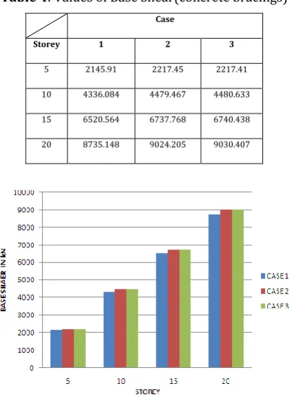
Table 4: Values of Base Shear(concrete bracings) Case
Storey 1 2 3
5 2145.91 2217.45 2217.41
10 4336.084 4479.467 4480.633
15 6520.564 6737.768 6740.438
20 8735.148 9024.205 9030.407
Fig -6: Variation of Base shear (concrete bracings)
Table 5: Values of Base Shear(steel bracings)
Case
Storey 1 2 3
5 2145.91 2160.60 2160.56
10 4336.08 4364.64 4365.24
15 6520.564 6564.78 6566.12
20 8735.14 8794.22 8797.30
[image:4.595.57.267.302.589.2]Fig -7: Variation of Base Shear (steel bracings)
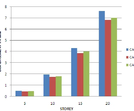
Table 6: Values of Displacement(concrete bracings) Case
Case 1 2 3
5 0.518 0.461 0.477
10 1.971 1.756 1.816
15 4.344 3.885 4.006
20 7.616 6.836 7.03
Fig -8: Variation of Displacement (concrete bracings)
Table 7: Values of Displacement (steel bracings)
Case
Storey 1 2 3
5 0.518 0.48 0.489
10 1.971 1.825 1.861
15 4.344 4.03 4.103
[image:4.595.333.540.307.592.2] [image:4.595.37.563.544.791.2]© 2017, IRJET | Impact Factor value: 5.181 | ISO 9001:2008 Certified Journal | Page 1355 Fig -8: Variation of Displacement (steel bracings)
4. CONCLUSIONS
In the study, performance of the structure under seismic loads for different heights i.e. 5, 10, 15, and 20 stories was studied. Behavior of structure with and without braces was studied and compared for steel and concrete braces.
Providing braces increases the lateral stiffness of the structure.
Due to the increase in stiffness, the lateral deformation of the structure is reduced compared to that of the bare frame.
The braces act as axially loaded members (truss members) when subjected to lateral seismic forces. As such the brace members are more effective in carrying the lateral forces than the frame members.
All the above factors, and the fact that the braces are easy to install, moment resisting frames, along with the braces is one of the most effective and commonly used seismic force resisting system.
Due to the increase in stiffness, the structure with braces is subjected to larger base shear as compared to the bare frame. As such the shear demand on the columns also increases.
5. SCOPE FOR FURTHER STUDIES
Same study can be done by varying the size of the building.
Seismic response for different configuration with various types of bracings can be studied.
Concrete bracings using higher grade of concrete and steel braces with different sections can be studied.
Seismic response for irregular structure can be studied.
Same study can be done using other software.
6. REFERENCES
[1] Beigi et al. (2010) “Gapped-Inclined Braces for Seismic Retrofit of Soft-Storey Buildings” ASCE, J. Struct. Eng., 2014, 140(11): 04014080
[2] Desai et al. (1989) “cyclic response of concrete bracing members”, ASCE, J. Struct. Eng., 1989, 115(1): 51-68 [3] Domínguez et al. (2012) “Case studies on the seismic
behavior of reinforced concrete chevron braced framed buildings” 2012 Elsevier, Engineering Structures 45 (2012) 78–103
[4] Hikino et al. (2013) “Out-of-Plane Stability of Buckling-Restrained Braces Placed in Chevron Arrangement” ASCE, J. Struct. Eng., 2013, 139(11): 1812-1822 [5] Jain (1985) “seismic response of RC frames with steel x
braces” ASCE, J. Struct. Eng., 1985, 111(10): 2138-2148 [6] Lie et al. (1988) “Strongback System: A Way to Reduce Damage Concentration in Steel-Braced Frames” ASCE, J. Struct. Eng., 2015, 141(9): 04014223
[7] Safarizki et al. (2013) “Evaluation of the Use of Steel Bracing to Improve Seismic Performance of Reinforced Concrete Building” 2013 Elsevier, Procedia Engineering 54 ( 2013 ) 447 – 456
[8] Valente (2013) “Seismic Protection of R/C Structures by a New Dissipative Bracing System” 2013 Elsevier, Procedia Engineering 54 (2013) 785 – 794
[9] Indian Standard Code of Practice of Plain and Reinforced Concrete IS: 456-2000, Fourth-Revision, BIS, and New Delhi.
[10] Indian Standard Recommendation for Earthquake Resistance Design of Structures IS: 1893-2002, Bureau of Indian Standards, New Delhi.
BIOGRAPHIES
Ms. Pooja D. Desai P.G Student
Dept. of Civil Engineering, KLS Gogte Institute of Technology,
Belagavi, Karnataka, India.
590008
Prof. Vikhyat S. Katti Assistant Professor