FM 55-9
"û
■
hi f/n •‘Z-à/, 01I
\
UNIT AIR MOVEMENT
PLANNING
DISTRIBUTION RESTRICTION: Approved for public release; distribution is unlimited.
HEADQUARTERS, DEPARTMENT OF THE ARMY
Pentagon Library (ANR-PL)ATTN: Military Documents Section Room 1A518, Pentagon
Cl, FM 55-9
Change 1 HEADQUARTERS
DEPARTMENT OF THE ARMY
Washington, DC, 14 October 1994
UNIT AIR MOVEMENT PLANNING
1. Change FM 55-9,5 April 1993, as follows:Remove old pages Insert new pages
1- 3 and 1-4 2- 1 through 2-12 2-15 and 2-16 2-21 and 2-22 2-27 and 2-28 2-39 and 2-40 5- 1 through 5-4 6- 3 and 6-4 6- 7 and 6-8 7- 1 and 7-2 7-5 through 7-8
A-3 through A-6 A-ll and A-12 A-15 through A-18 B-3 and B-4 D-l and D-2 D-5 and D-6 D-9 and D-10 E-3 and E-4 F-15 through F-17
Glossary-1 and Glossary-2 References-3 1- 3 and 1-4 2- 1 through 2-12 2-15 and 2-16 2-21 and 2-22 2-27 and 2-28 2-39 and 2-40 5- 1 through 5-4 6- 3 and 6-4 6- 7 and 6-8 7- 1 and 7-2 7-5 through 7-8
A-3 through A-6 A-ll and A-12 A-15 through A-18 B-3 and B-4 D-l and D-2 D-5 and D-6 D-9 and D-10 E-3 and E-4 F-15 through F-17
Glossary-1 and Glossary-2 References-3
2. A star (*) marks new or changed material.
3. File this transmittal sheet in front of the publication.
By Order of the Secretary of the Army:
Official:
MILTON H. HAMILTON
Administrative Assistant to the Secretary of the Army
GORDON R. SULLIVAN
General, United States Army Chief of Staff
DISTRIBUTION:
Active Army, USAR, and ARNG: To be distributed in accordance with DA Form 12-11E, requirements for FM 55-9, Unit Air Movement Planning (Qty rqr block no. 1184).
*FM 55-9
Field Manual HEADQUARTERS
No. 55-9 DEPARTMENT OF THE ARMY
Washington, DC, 5 April 1993
UNIT AIR MOVEMENT PLANNING
TABLE OF CONTENTS
Page
PREFACE iv CHAPTER 1. INTRODUCTION TO AIR MOVEMENT
Introduction 1-1 History of Airlift 1-1 Air Movement Authority 1-1 Deployment Instructions 1-1 Types of Movements 1-1 Nontactical Movement 1-1 Tactical Movement 1-2 Safety 1-2 Troop Movement on an Airfield 1-2 Flight Line Safety 1-2 Risk Management 1-4 CHAPTER 2. AIR MOBILITY COMMAND AIRCRAFT
Introduction 2-1 Allowable Cabin Load 2-1 Aircraft Center of Gravity Limits 2-1 Cargo Load Center of Balance Limits 2-1 Aircraft Characteristics 2-2 C-130 Characteristics 2-3 C-141 Characteristics 2-8 C-5 Characteristics 2-13 KC-10 Characteristics 2-15 C-17 Characteristics 2-38
DISTRIBUTION RESTRICTION: Approved for public release; distribution is unlimited. ?This publication supersedes FM 55-9,31 August 1981. /
FM 55-9
Page
CHAPTER 3. CIVIL RESERVE AIR FLEET AIRCRAFT
Introduction 3-1 Load Planning for CRAF Aircraft 3-1 B-707 3-3 B-747 3-3 DC-8 3-8 DC-10 3-13 L-1011 3-13 CHAPTER 4. UNIT AIR MOVEMENT PLANNING GUIDELINES AND CONSIDERATIONS
Introduction 4-1 Aircraft Requirements 4-1 Weight Method 4-1 Type-Load Method 4-1 Automated Air Load Planning System 4-2 Air Movement Planning Worksheets 4-2 CHAPTER 5. BASICS OF AIRCRAFT LOAD PLANNING
Introduction 5-1 Load Planning Considerations 5-1 Types of Loads 5-1 Concentrated Loading 5-1 Palletized Loading 5-2 Aircraft Loading Data 5-2 Principles of Moment 5-2 Load Center of Balance 5-4 Placement of Aircraft Loads 5-5 Load Planning 5-5 Templates 5-5 Loading Procedures 5-7 Automation 5-8 AALPS 5-8 CALM 5-8 CHAPTER 6. LOAD SHORING
Introduction 6-1 The Need for Shoring 6-1 Types of Shoring 6-2 Rolling Shoring 6-2 Parking Shoring 6-3 Bridge Shoring 6-4
FM 55-9 CHAPTER?. APPENDIX A. APPENDIX a APPENDIX C. APPENDIX D. APPENDIX E. APPENDIX F. GLOSSARY . REFERENCES Page Sleeper Shoring 6-4 Special Shoring 6-5 Size and Condition of Shoring 6-5 Transport of Shoring 6-7 Shoring Requirements 6-7 Formulas 6-7 CARGO RESTRAINT
Introduction 7-1 Principles of Cargo Restraint 7-1 Restraint Criteria 7-2 Direction of Restraint 7-2 Tie-Down Devices 7-2 Tie-Down Device Strength 7-4 Required Number of Tie-Down Devices 7-5 Percentage Restraint Chart 7-5 Percent of Angle of Tie 7-8 Pallets 7-10 COMMON AIR MOBILITY COMMAND AIRCRAFT CONFIGURATIONS A-l PREPARATION OF EQUIPMENT AND PERSONNEL B-l AIR MOVEMENT PLANNING WORKSHEET C-l 463L CARGO SYSTEM D-l TEMPLATES E-l MATERIALS-HANDLING EQUIPMENT F-l Glossary-1 References-1 INDEX Index-1
FM 55-9
PREFACE
This manual provides guidance for Army personnel involved in unit movement on Air Force-provided airlift, including commercial charter and Civil Reserve Air Fleet (CRAF) aircraft It gives an overview of air transportability considerations for Army personnel and equipment and describes aircraft loading procedures and related fundamentals and techniques. It provides in-depth information on aircraft characteristics, the 463L pallet system, and CRAF.
This manual, with FM 55-12, AMC Pam 55-41, and TM 38-250, gives unit commanders and movement personnel the basic data to plan and execute successful movements via airlift
The proponent of this publication is the US Army lYansportation School Send comments and recommen- dations on DA Form 2028 (Recommended Changes to Publications and Blank Forms) to Commandant, US Army Transportation School, ATTN: ATSP-TDL, Fort Eustis, VA 23604-5389.
Unless this publication states otherwise, masculine nouns and pronouns do not refer exclusively to men.
FM 55-9
CHAPTER 1
INTRODUCTION TO AIR MOVEMENT
INTRODUCTION
Air movement is initially the primary transportation method used during crisis response. World situations that call for a rapid response by the armed forces use airlift to quickly move to an area of operations. Air movement of units requires detailed planning at all levels of command. This chapter gives a brief overview of the history of airlift and air movement missions and respon- sibilities. It also provides general instructions for conducting an air movement, emphasizing safety.
Air load planners must successfully complete one of three airlift planning courses to be certified to plan and sign DD Form 2130-series cargo manifests. These courses are the AMC Affiliation Airlift Planners Course, the US Army Air Deploy- ment Planning Course (ADPC), and the USMC Landing Force Training Command Pacific (LFTCPAC) Aircraft Load Planning Course. According to AMC Regulation 55-3, this certifica- tion is valid for two years after completion of the course. As of the date of this publication, recer- tification procedures have not been defined. Con- sult the original training source for further details.
HISTORY OF AIRLIFT
Airlift has played an important part in nearly every major conflict since World War I. Throughout World War II, in all theaters of opera- tion, commanders frequently airlifted troops and supplies. The Berlin Airlift was the first real test of airlift operations in a noncombat role. Without airlift, the Soviet Union would have been able to starve West Berlin into submission. Commanders in the Korean conflict used airlift to resupply many of the United Nation’s forces. Our modern airlift force was developed during the Vietnam War, with modern, faster, and more efficient airlift replacing earlier models. Early in the Vietnam War, it took days to transport a few thousand pounds of cargo from the United States to the battle area. At the end of the war, more than 200,000 pounds could be transported the same distance with one airplane in less than 24 hours. During Operations Desert
Shield/Desert Storm, more than 509,000 pas- sengers and 700,000 tons of cargo were moved by more than 18,500 airlift missions.
AIR MOVEMENT AUTHORITY
AR 220-10 specifies who has authority to authorize unit air movement. The Joint Chiefs of Staff (JCS), in coordination with the Department of Defense (DOD) and the Department of the Army (DA), authorizes unit air movement between over- seas major Army commands or from an overseas major Army command to the continental United States (CONUS). Headquarters DA authorizes unit movement by air from or within CONUS. DA nor- mally provides instructions and movement authority to the Army components of unified commands to implement DOD and JCS directives.
DA publishes the movement directive. This basic document is the authority for the appropriate commander to prepare a unit for movement and to execute the move.
DEPLOYMENT INSTRUCTIONS
Army major commands or Army components of unified commands issue deployment instruc- tions as a guide for the moving unit. These instruc- tions generally cover criteria for deployable personnel, type of equipment to be taken, medical support to be provided, and special logistical and soldier support instructions. AR 220-10 outlines standard procedures for preparation for overseas movement (POM). Data in this manual are consis- tent with AR 220-10.
TYPES OF MOVEMENTS
The type of movement is based on the urgency of the situation. The type of movement directed in the deployment instructions determines the method of loading. The two types of movement are nontactical movements and tactical movements. Nontactical Movement
A nontactical movement is a movement in which units, personnel, equipment, and materiel
FM 55-9
move when no enemy interference or contact is anticipated. It emphasizes economical use of the aircraft cargo space and maximum use of the allow- able cabin load (ACL). ACL is the amount of cargo and passengers (as determined by weight, cubic displacement, and distance from origin to destination) that may be transported by a specific type of aircraft. Unit integrity and unloading sequence are major considerations when plan- ning a nontactical movement, but efficient economy of space utilization has the highest priority (Figure 1-1). Units may not be required to be operational upon unloading.
Ihctical Movement
A tactical movement is a movement of units, personnel, equipment, and materiel that is organized, loaded, and transported to facilitate accomplishment of a tactical mission. Unit integrity is the primary consideration in move- ment, not economy of space. Maximum use of the aircraft ACL remains the ultimate movement goal, but the commander’s sequence of employment and unit integrity receives the highest priority. Units should be configured to conduct immediate opera- tional missions upon unloading (Figure 1-1).
SAFETY
Commanders and all personnel must em- phasize safety and use the principles of risk management when making decisions. Safety in training and execution is force protection. Protect- ing the force through risk management means per- forming to standards, correcting unsafe behavior, and making good risk decisions. Vehicle accidents kill 250 soldiers and cost the Army $100 million dollars each year. These losses are preventable by taking the proper precautions. The first fatality in Operation Desert Shield was an Air Force airman struck by a vehicle on the flight line.
FM 55-12 covers specific safety measures during aircraft loading. Other safety rules are below. Tkoop Movement on an Airfield
Before troops move onto an airfield, airfield operations personnel grant permission and the movement is coordinated with designated airfield personnel who provide guides or appropriate instructions. Troops move on the airfield in con- trolled formation only; halt at least 100 feet from
the edge of runways, taxi strips, and ramps; and get clearance before crossing. The Ihnker Airlift Con- trol Element (TALCE) may identify entry control points (ECPs) for access of troops onto flight lines.
Flight Line Safety
Personnel on the flight line—
• Must not smoke on the aircraft parking ramp area except in designated smoking zones. • Must not walk in front of any aircraft when
the engines are running. Personnel must never walk within the propeller arc. • Must walk around the outside of the wing
tips to avoid the auxiliary power units’ blast or heat exhaust and the propeller or jet intake area.
• Must observe a 15 mph speed limit for all vehicles on the flight line.
• Must observe a 5 mph speed limit for all vehicles within 25 feet of an aircraft. However, the speed of vehicles will not exceed 3 mph (walking speed) when within 10 feet of the aircraft, to include movement inside the aircraft. • Must not approach within 50 feet of an
engine intake nor within 200 feet of the blast area to the rear when jet engines are running. On propeller-driven aircraft, the danger area is 10 feet in front of the propeller and 200 feet to the rear.
• Must not drive any vehicle under any part of the aircraft.
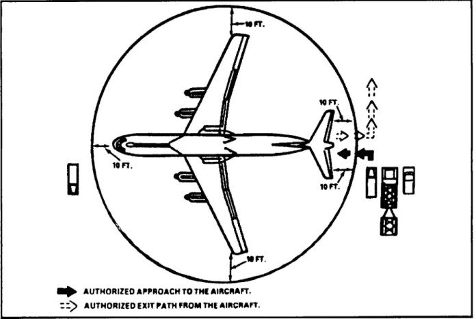
• Must not drive a vehicle within 10 feet of an aircraft without a walking guide to observe clearance between vehicle and aircraft. This “circle of safety” extends 10 feet in front of the nose, 10 feet behind the tail, and 10 feet outboard of each wing tip (Figure 1-2). • Must not drive vehicles, except those being
loaded or unloaded, directly toward an aircraft or park closer than 10 feet from an aircraft.
• Must approach an aircraft in a vehicle with the driver’s side nearest the aircraft. Per- sonnel park the vehicle perpendicular to the aircraft fuselage.
Cl,FM 55-9
• Must not allow trash or debris to be thrown on the flight line. Personnel must also en- sure that canvas or small pieces of equip- ment are secure to prevent the jet exhaust from blowing them around.
* Must not stand or walk directly in front of or behind vehicles being driven or backed into the aircraft.
• Must not back vehicles toward or into an aircraft without spotters placed at the front and rear corners of the vehicle. (The air- craft loadmaster directs all backing.) Spot- ters should not be directly in front of or behind any moving vehicle.
• Must not stand between a moving vehicle and any stationary object, such as another vehicle, aircraft, or buildings.
Bon
* NONTACTICALLY LOADED AIRCRAFT
TACTICALLY LOADED AIRCRAFT
UU Jl H
TROOPS BOARDING AN AIRCRAFT
‘Figure 1-1. Types of Movement.
C1,FM 55-9 & WFT
A
FTA
A
>
X
0
10 FT M FT^ AUTHORIZED APPROACH TO THE AIRCRAFT. : AUTHORIZED EXIT PATH FROM THE AIRCRAFT.
Figure 1-2. Circle of Safety.
Risk Management
Risk management is the process of making operations safer without interfering .with essential mission values. The process focuses a leader on issues that could result in losses and then requires the leader to consider risk reduction measures that allow mission accomplishment while minimizing losses. The four principles of risk management are—
• Accept no unnecessary risk. An unneces- sary risk is one that if eliminated would still allow for mission accomplishment.
• Make risk decisions at the proper level con- sistent with your local command policy. • Accept risk only when benefits outweigh
costs.
• Manage risk in the concept and planning stages whenever possible.
The risk management process is to—
• Identify the hazards that will be encoun- tered.
• Assess the risk of those hazards by asking what are the most likely injuries or damage that might occur, and what is the probabil- ity of those losses.
• Determine what kind of control measures could be used to reduce risk. These might be speed limit controls, more supervision, scheduling, route changes, protective equipment, more training, or more indepth instructions. Once available controls are considered, decide which of those controls to implement.
• Implement controls.
• Supervise. Remember that NCOs make it safely happen.
Cl,FM 55-9
CHAPTER 2
AIR MOBILITY COMMAND AIRCRAFT
INTRODUCTION
This chapter describes Air Mobility Com- mand (AMC) aircraft and provides the necessary planning data to effectively prepare load plans. Personnel who prepare load plans must recertify every two years.
The AMC aircraft of main concern are the C-130, C-141, C-5, KC-10, and C-17. With some exceptions, their cargo compartments can be con- figured to hold general bulk or palletized cargo, vehicles/equipment, troops, paratroopers, or cargo rigged for airdrop. The KC-10 cannot be rigged for airdrop. The wide range of cargo car- ried by these aircraft, along with many options for loading, provides great flexibility in moving troops and equipment.
Each of these aircraft have medium- to long- range mission capability. All are equipped with roller conveyor systems for using the 463L pallet system. The C-130, C-141, C-5, and C-17 have hydraulically activated ramp systems to ease load- ing and unloading. The C-141, C-5, KC-10, and C-17 also have aerial refueling capability.
NOTE: The planning data for the C-17 are projected capabilities only. They do not reflect the results of any DOD-certi- fied tests and evaluations. Use only cur- rent data as a reference for possible future capabilities. Consult affiliated AMC representatives for actual "flyaway" data.
ALLOWABLE CABIN LOAD
The load planner must know the approved allowable cabin load for a particular aircraft. ACL is the weight of unit personnel, equipment, and materiel that an aircraft can carry. Several varying factors, such as distance, route to be flown, fuel load, weather, and winds, impact on the ACL. De- parture and arrival airfield characteristics also fac- tor into determining the ACL.
For general airlift planning factors, use the following ACLs: AIRCRAFT C-130 C-141 C-5 KC-10 C-17 ALLOWABLE CABIN LOAD 25.000 pounds 50.000 pounds 150.000 pounds 100.000 pounds 153,500 pounds AIRCRAFT CENTER OF GRAVITY LIMITS
Another factor to consider in load planning is center of gravity (CG) limits. Each aircraft has certain limits in which it must be balanced. If an aircraft is not balanced properly, it may not take off or land safely. In extreme cases, it cannot fly safely. The load planner directly affects this bal- ance factor when loading cargo aboard an aircraft. Loads must not cause the aircraft to exceed its balance limits. The CG of any aircraft is the point on the aircraft at which the aircraft would hang in a level, balanced horizontal position if hoisted off the ground by a cable. It is an exact and specific point on the aircraft. Fortunately, through design characteristics and mechanical devices, each air- craft allows some variation with its CG. Otherwise, load planning would be almost impossible.
These variations, or CG limits, provide the load planner with flexibility in preparing various load configurations for each aircraft. As long as the effect of the cargo weight is kept within these CG limits, the aircraft can be safely operated.
CARGO LOAD CENTER OF BALANCE UMITS
To keep the cargo weight within the aircraft CG limits, the cargo load center of balance (CB) must be identified. The combined center of bal- ance (CCB) of the cargo load is then placed in the cargo compartment within a prescribed design limit for the aircraft. (See Chapter 5 for more
Cl,FM 55-9
information.) Table 2-1 provides AMC guidelines for use in airlift planning.
In general, floating CB criteria means as the cargo weight increases, the total cargo center of balance windows decrease. When total cargo weights fall between given weights, use the most restrictive (next higher) center of balance window. For example, a 46,000-pound load on a C-141 uses the 50,000-pound window of 880-950.
Unit air movement planning personnel must comply with established planning data when load planning unit equipment and personnel deploy- ments by air.
The CB window numbers are referred to as fuselage station (FS) numbers. They represent the distance (in inches) aft from the aircraft reference datum (RD) line at which point the cargo load
must balance. The FS numbers are clearly marked on the cabin walls to use as reference points when loading.
AIRCRAFT CHARACTERISTICS Load planners must consider the characteris- tics of each aircraft. These characteristics include- • The size of the cargo door and its location
and height above the ground.
• The size and shape of the cargo compart- ment.
• The strength of the aircraft floor.
• The location, number, and type of seats available for airlifting troops.
• Aircraft configurations (Appendix A).
‘Table 2-1. Floating Center of Balance Criteria.
WEIGHT C-130 C-141 C-5 KC-10 C-17 5,000 10,000 15.000 20.000 25.000 30.000 40.000 50.000 60.000 70.000 80.000 90,000 100,000 120,000 150.000 175.000 245.000 291.000 400-550 400-550 475-530 485-530 510-530 510-530 515-530 630-1000 770-1000 770-1000 835-970 835-970 860-960 870-950 880-950 890-950 890-940 400-1000 400-1000 400-1000 409-1370 400-1370 670-1380 835-1380 935-1380 1000-1380 1050-1380 1085-1390 1115-1390 1135-1390 1170-1390 1200-1390 1225-1390 1280-1390 1315-1390 530 530 542 542 810 810 942- 1022- 1075- 1115- 1142- 1165- 1162- 1210- 1234 1235- 840 1105 1238 1238 1205 1205 1252 1280 1298 1311 1321 1329 1335 1345 1354 1354 350-960 350-940 350-930 350-930 360-925 450-925 560-925 620-925 630-920 690-920 720-920 740-920 750-920 770-910 810-900 830-900 2-2
C1,FM 55-9
If a complete file of Air Force publications is not available, the unit’s affiliated AMC Airlift Con- trol Squadron (ALCS) will assist the load planner. The ALCS is an extension of the unit’s staff for all
airlift planning. See FM 55-12 for more informa- tion on the affiliation program.
Table 2-2 is a quick reference for AMC air- craft. Refer to the individual aircraft discussed later in this chapter for more detailed information. * Table 2-2. AMC Aircraft.
Model Design Manufacturer Popular Name Cargo Compartment Dimensions Length (inches) Height (inches) Width (inches) Aircraft Ramp Length (inches) Usable Loading Space (inches) Troop Load Over land Over water C-130 Lockheed Hercules 624 108 1233 132 597 904 806 C-141 C-5 KC-10 C-17
Lockheed Lockheed McDonnell McDonnell Douglas Douglas Starlifter 1,251 109 123 1,215 200 160° Galaxy 1,733 162 228 133 (Fwd) 116 (Aft) 155 1,726 73° Extender Globemaster 73s 1,508 108 218 None 1,416 10(B) 69(D) 69 1,075 1481 1582 216 257 1,022 54 SF 102 SL 158 DL 102
’Under and forward of the wing box. 2Aft of the wing .
3With dual rails installed, the cargo compartment floor is limited to 106 inches widefor cargo loading.
4Troop seating, except seat 11 left and 11 right must be installed in pairs. 5Troop seating in the overhead troop compartment.
*6 Total number of personnel (including flight crew) allowed during over-water flights due to the number of emergency ditching exits.
Legend
SF - Side-facing seating only
SL - Single centerline and side-facing seating *DL - Double centerline and side-facing seating
C1,FM 55-9
AMC
d
EZ=]
Figure 2-1. C-130 Aircraft.
♦Passenger Considerations. The C-130 does not have a separate passenger compartment, and passengers compete for available ACL. For plan- ning purposes, estimate each passenger to weigh 210 pounds. This weight may vary with type of mission (refer to FM 55-12) and should be con- firmed with AMC as early as possible. When using side-facing seats, plan for a maximum of 29 passen- gers. The C-130 will carry a maximum of 90 pas- sengers (80 including flight crew for over water flight).
NOTE: Side-facing seats number 1 through 10 and 13 through 22 left and right must be installed in pairs. Seats 11 and 12 must be installed with 10 and 13 respectively, as these seats will not stand alone.
Palletized Cargo Restrictions. The C-130 can accommodate up to six 463L pallets. Usable sur- face dimensions of a 463L pallet are 84 inches long by 104 inches wide. Pallet criteria according to position, weight, and height are in Figure 2-2.
For pallet positions 3 and 4, maintain a 6-inch aisle along the narrow side of the pallet. Do not exceed an overall dimension of 84 inches long, 98 inches wide, and 96 inches high. This will provide the necessary aisleway for emergency exit of the aircraft.
For pallet position 6, maintain an 18-inch aisle. Pallet cargo dimensions will not exceed 86 inches wide, 84 inches long, and 76 inches high. This provides access to the latrine, cargo loading aids stowed in the cargo door, and to the aft escape exit hatch on the aft end of the cargo ramp.
Loading Guidance. The cargo area dimen- sions in Figure 2-3 are for general planning pur-
poses only. Exceptions may include items config- ured according to TB 55-46-1 or loaded according to the aircraft loading manual. The schematic in Figure 2-3, extracted from DD Form 2130-2 (C-130 A/B/E/H Cargo Manifest), shows the fuselage sta- tion numbers and pallet position center of bal- ances.
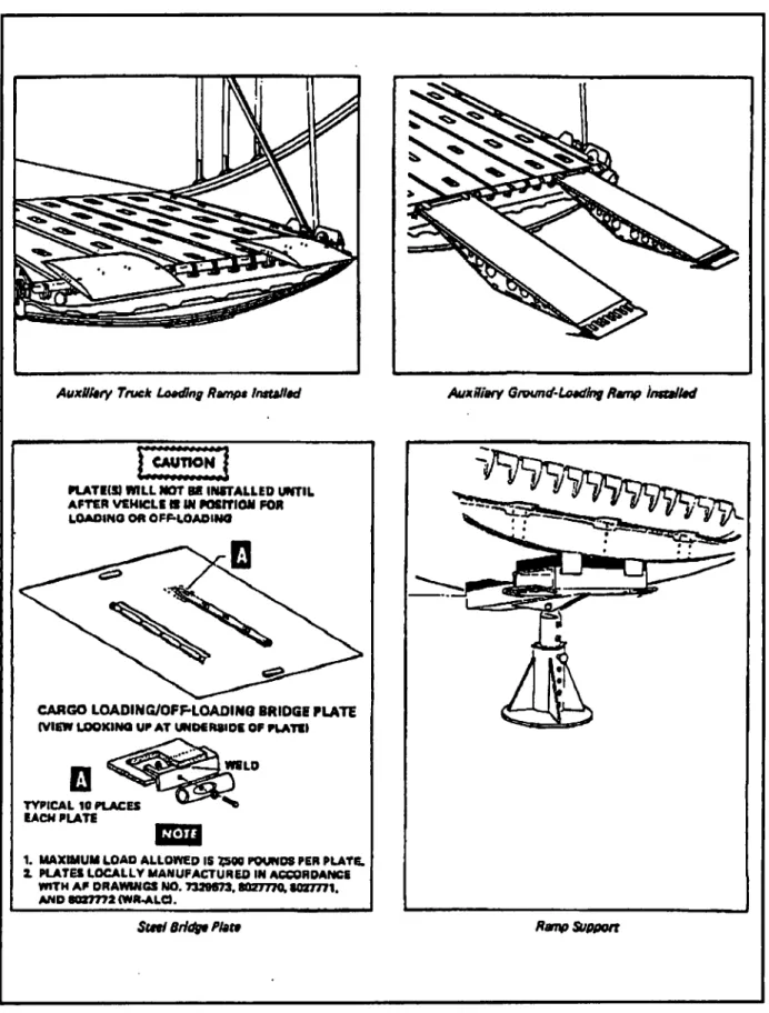
A number of loading aids are available to more conveniently load the C-130. They either come with the aircraft or are available as options from the supporting AMC TALCE or servicing aerial port. In addition to the primary loading aids in Figure 2-4, the following aids are available (all but the wheeled pry bars are in the aircraft):
Wheeled pry bars for handling boxes and crates in the cargo compartment.
• A portable electric winch for moving cargo in and out of the aircraft.
• Internal electrical power outlets to provide power for aids when loading the aircraft. • An auxiliary power unit to provide electric-
ity and hydraulic pressure to assist aircraft
loading.
• A public address system consisting of loud- speakers, microphones, headsets, and ex- tension cords for giving loading instructions and to control the loading op- eration.
• Lighting to illuminate the cargo compart- ment and door area during night loading. • Snatch blocks (loading pulleys) to help
move cargo in and out of the aircraft.
Cl,FM 55-9
h
« « « 9
322 42t 512
GROUND ESCAPE BOT* (4)
DUAL RAL svsrai
NOTE: Diagram is not to scale.
MAXIMUM DIMENSIONS1
PALLET POSITION (PR WEIGHT 2 HEIGHT 2
(in pounds) (in inches) including weight of
the pallets and nets
1-4 10,355 962
5 8,500 962
6 4,664 76 1 Pallet position maximum dimensions may befurther restricted by temporarily installed aircraft equip-
ment. Contact your affiliated AMO ALCS for specific guidance.
^Maximum singlepallet weight forcargo secured with nets and stacked above 96inches (notto exceed 100 inches) shall not exceed 8,000pounds.
Figure 2-2. C-130 Pallet Positions.
CIJO A/l/H
r ¿T
T"
40ca. CABAO MUI? 009TIOMI 1— on COHO «tSIWClIOMS/IMMO .. L - *■ y ■1 y IA VI -B— on -OTH»,, ~i • QT Q~ CT Q- 1222282?®°®°*® o’ Qm o* or a* tr tr a* a- <r tr a* a- <r
Oè O— «4*0- A-*O* «— o*«
e. 9. 0«, 9., 0 o. BK O« A* o» <Xi.
o e e o o o e •/« oiJôîôïo^ooooot - s = = ei_= «— io a AA aA_ft A a A n o A TTTTTTTTTTTTTTTTTO-OTIIJ ' ' ' ' ; ' t t t t • 9 t. o c o • 9 • 9 « 14
* I J» Î W Ï )S
7I W Ï Vw I I I *Íf I Ur I
nñ
7*7I ftól I M
7I
1(7 1*7 IS7 177 417 417 4«7 U7 177 *17 4S7 *47 TUT 7*7 M7 M*NOTE: Diagram is not to scale.
USABLE CARGO AREA RAMP LIMITATIONS
vooo ia raowN MVOO la teooww MJOOO IO TWOOWM SCM ST4NCMON VINT SNOu/Douaa MATS
NO nooft LCAOCD CAiGO
ttoo? 0000
VMKU IStAOWAT
Length - 597 inches Width -106 inches* Height -102 inches*
Pallet: Height - 76 inches Weight - 4,664 pounds Vehicle: Height - 80 inches
* Weight - 3,500 pounds per axle(single axle, only item on ramp )
‘Special loading procedures apply when considering items that exceed 106 inches wide or 102 inches high. Contact your affiliated AMC ALCS for more detailed informa- tion.
: Figure 2-3. C-130 Schematic.
C1.FM 55-9
AuxUltry Truck Loading Rampa Installed Auxiliar/ Ground-Loading Ramp imtallad
CAUTION
►LATHS) WILL NOT B8 INSTALLED UNTIL AFTER VEHICLE B IN MSITION FOR LOAOINO OR OFF-LOAOINO
câ
CARGO LOADING/OFF-LQAOINO BRIDGE PLATE
(VIEW LOOKING UP AT UNDERSIDE OF PLATE)
WELD
V
TYPICAL 10 PLACES EACH PLATE
1. MAXIMUM LOAD ALLOWED IS 3500 POUNDS PER PLATE. 1 PLATES LOCALLY MANUFACTURED IN ACCORDANCE
WITH AP DRAWINGS NO. 732M73. «027770. «027771. AND 8027772 (WR-ALO.
Steal Bridge Plate Ramp Support
Figure 2-4. C-130 Loading Aids.
C1.FM 55-9
Rolling Stock Restrictions. Whenever possible, plan to load rolling stock on the treadways of the aircraft as shown in Figure 2-5. Vehicles with pneumatic tires must have a minimum space of 48 inches between axles. If this space cannot be ob- tained, the axles are considered as a single axle. When load planning and actual loading, the single axle limitations apply (Figure 2-5). Vehicles whose operational height exceeds 102 inches must be re- duced in height unless certiñed to be shipped at a higher height according to TB 55-46-1 or the air- craft loading manual.
When the load consists of palletized cargo or floor-loaded cargo secured with cargo straps, maintain a 30-inch space between the cargo and the nearest forward occupied seat. When cargo is secured with chains, the 30-inch rule does not apply.
Do not exceed the following limitations: • Pounds per square inch.
• Pounds per linear foot (PLF). • Axle weight.
• Wheel weight.
Ikacked Vehicle Loading. Figure 2-6 shows an M577 tracked vehicle loaded aboard a C-130 air- craft. The following example is the method to determine loadability and placement on the air- craft floor.
EXAMPLE:
A tracked vehicle is to be loaded aboard a C-130. The tracked vehicle weighs 22,000 pounds. The weight-bearing area of the tracks is 8 feet long (the length of track that contacts the cargo floor in longitudinal plane).
between treadways — -
f
i
245 337
682 737
/
1
869
FUSELAGE STATION *257-337 337-682 682-737 RAMP TREAD- WAYS BETWEEN TREAD- WAYS TREAD- WAYS BETWEEN TREAD- WAYS TREAD- WAYS BETWEEN TREAD- WAYS TREAD- WAYS BETWEEN TREAD- WAYS PSI 50 50 50 50 PLF 1400 3000 1600 1400 500 TONGUE1 LOAD 2000 2000 2000 450 MAX AXLE LOAD 6000 5000 13000 5000 6000 5000 2500? 1200 MAX WHEEL LOAD 3000 2500 6500 2500 3000 2500 1250 6001 Do not exceed 50 pounds per square inch (psi).
2A single axle up to 3,500 pounds in weight may be transported on the aircraft ramp, provided it is the only item on the ramp.
* Figure 2-5. C-130 Flight Limitations Chart.
C1,FM 55-9 ri »2 tï -4 ri“® r7 -IOTUI I a • u u u- ■"^0‘‘ii i* •- •* ■’ »»•••» »•m* •- •• .«.■« 1.1« *.«*«. » » " SB , siá •ffc O i Zi CO ♦ -=—i a • • •
LC-C-E-E-SL
CT«^ «. I. «. » * ^ * i 1.2x3.4xfi.«<.7-1^9-10^114 vrîMïlîîlïtitf-246
J
2^7I
3I7I
967I
397i
437I
477I
SI?I
667I
G87I
«^7i^^l
2S7 »7 317 377 417 467 407 — — — « i a ■ "S 4 4 • & * ■ « * 767I air I
947i
837 577 617 067 807 737 767 027 868Figure 2-6. Tracked Vehicle on C-130.
To determine the pounds per linear feet, di- vide the weight of the vehicle by the contact portion of the track. The answer is the amount of PLF being created.
22,000 pounds (weighlof vehicle)
8 feet (floor contact area of track) = 2,750 pounds PLF The vehicle creates 2,750 PLF. It can be safely transported, but it must be loaded between fuse- lage stations 337 to 682 (area where tracks must contact the aircraft floor). Allowable limit in this area is 3,000 PLF on the treadways.
Helicopter Loading. Helicopters with major disassembly can be airlifted. Table 2-3 provides data for use in mission planning (for specific guid- ance, refer to TO. 1C-130A-9):
C-141 Characteristics
The C-141, nicknamed Starlifter, is a high- wing, heavy transport airplane with four turbofan engines (Figure 2-7). Its mission is to transport unit personnel, equipment, and materiel world- wide. The C-141 is the backbone of the strategic airlift capability of the US Air Force. It is most likely the aircraft to be used for all basic movement planning.
Table 2-3. C-130 Helicopter Loading Data.
TYPE/MODEL AH-1 UH-1H OH-58 LCH-58 OH-6 LOADING METHOD Major Disassembly Major Disassembly Major Disassembly Major Disassembly Major Disassembly TOTAL UNITS 1 1 3 2 3 2-8
C1.FM 55-9
€
B
<
□
s
Figure 2-7. C-141 Aircraft.
Passenger Considerations. Like the C-130, the C-141 does not have a separate passenger com- partment. For planning purposes, estimate each passenger to weigh 210 pounds. This weight may vary with type of mission (refer to FM 55-12) and should be confirmed with AMC as early as possi- ble. When using side-facing seats, plan for a max- imum of 98 passengers. The C-141 will carry a maximum of 200 passengers (160 including flight crew for over water flights).
NOTE: All side-facing seats except num- ber 1 left and right must be installed in pairs. Seat number 1 will not stand alone. Palletized Cargo Restrictions. The C-141 can accommodate up to 13 463L pallets. Pallet posi- tion criteria according to position, weight, and height are in Figure 2-8.
Loading Guidance. The cargo area dimen- sions in Figure 2-9 are for general planning pur- poses only. Exceptions may include items configured according to TB 55-46-1 or loaded ac- cording to the aircraft loading manual. The sche- matic in Figure 2-9, extracted from DD Form 2130-3 (C-141B Cargo Manifest), shows the fuse- lage station numbers and pallet position center of balances.
*To more conveniently load the C-141, a num- ber of aids come with the aircraft or are available as options from the supporting AMC TALCE or
aerial port. With the exception of the ramp sup- port, the C-141 aircraft has the same type of equip- ment listed Figure 2-4 for the C-130 aircraft.
Rolling Stock Restrictions. Whenever possi- ble, plan to load wheeled and tracked vehicles on the treadways. Vehicles whose operational height exceeds 102 inches must be reduced in height un- less certified to be shipped at a higher height ac- cording to TB 55-46-1 or the aircraft loading manual.
Do not load cargo that touches the floor or overhangs between fuselage stations 292 and 322. Do not stow any wheel loads outboard of the treadways next to the troop doors. The total com- bined loaded cargo weight between fuselage sta- tions 322 and 678 will not exceed 45,000 pounds. Cargo loaded on the ramp for flight will not have the CB of cargo positioned aft of fuselage station 1473. When the load consists of palletized cargo or floor-loaded cargo secured with cargo straps, maintain a 30-inch space between the cargo and the nearest forward occupied seat. When cargo is secured with chains, the 30-inch rule does not apply. The part of a vehicle that is loaded under the crew rest facility (fuselage stations 322 to 378) will not exceed 80 inches in height measured from the aircraft floor. Do not exceed the limitations in Figure 2-10.
To determine aftmost axle location, use the following procedures (Figure 2-11):
C1,FM 55-9
TVacked Vehicle Loading. When planning air movement, there are two types of tracked vehicles: combat vehicles and construction vehicles. The basic difference is the rubber pad protection on the tracks that prevents damage to the ramp and the aircraft floor.
*All vehicles with metal tracks, cleats, studs, or other gripping devices that will damage the floor require rolling and parking shoring (see Chapter 6). For construction vehicles with cleats, the min- imum thickness for rolling and parking shoring is 3/4 inch. Planking must be thick enough for cleats or lugs to sink into and for distribution of the load so as not to exceed aircraft limitations. Tracked vehicles with serviceable rubber pads do not re- quire shoringifthe aircraft floor limitations are not exceeded. Rubber pads must protrude beyond the steel track so that no portion of the metal track contacts the cargo floor.
Combat vehicles. Tracked combat vehicles have rubber pads on the individual track segments. Generally, they are limited to a maximum practical
gross weight of 44,00 pounds. More specific limits are as follows: MAXIMUM AXLE WEIGHT (in pounds) 5.000 5.001 to 5,500 5.501 to 6,500 6.501 to 7,900 7,901 to 10,000 MINIMUM REQUIRED SHORING 3/4 inch 1 inch 1 1/2 inch 2 inch 3 inch
Approximate axle weights for vehicles with five axles or less by dividing the gross vehicle weight (GVW) by the number of axles minus 0.5. For example, the weight of a vehicle with five axles would be divided by 4.5.
Approximate axle weights for vehicles with six or more axles by dividing the gross vehicle weight by the number of axles minus 1.0. For example, the weight of a vehicle with seven axles would be divided by six.
GROUND ESCAPE EXITS (7)
g I
I
3
n M 4 n83 I
I I I
t83
« 471 561 9 661 9 7419
6319
6219
10119
11019
11919
? $ 3 3 $ NOTE: Diagram is not to scale.J
9
1281 1371
9
14729
3
3
H
MAXIMUM DIMENSIONS PALLET POSITION (PP) WEIGHT* HEIGHT
1 2-12
13
(in pounds)
including weight of the pallets and nets
10.355 10.355 7,500 (in inches) 76 96* 76 "Maximum single pallet weight for cargo secured with nets and stacked above 96 inches (not
to exceed 100 inches) shall not exceed 8,000 pounds.
Figure 2-8. C-141 Pallet Positions.
Figure 2>9. C-141 Schematic. rj IO j»i I Al D
C.B CAICO PAUII rosnioHs
i r
le oeoôoôoôoôoôoôoôoôoôoôoôoôoôoëoôoôo'ôoôoôoôoooôoo
« «K » a g « 8 k
atgDi585aôaô»ô»ô8ôaoaDaô»stQaaaiiâQ«oA5»» a o a Q a a a a & &—i—c—i
0 0-0- o o o o o O O O O U o o o o
“5—5—5—5—5—5—3—?—3—3—3—Ç—3—3—5“ “5—?—3—?—5" TTTT 3 ?”
oooooeoeoooooooooooooooooooooe o o o o o o o o o o o
ja i iilii* i ilte rl »aiiioaa ànauiuaniitaujuawiaaTiinaiiâMâMjinpiiiaiiâKia aiii8iiij«a»iiiepAM»iii«i<iioaqâ«<wi<t«qi«n«i ^ . î_ .3 . Ä. K - tftt 61 s
ivilT)« fT/i I Vis | 4» | 4«t | s» | s/t | Jia ! «sa | «la | rsa | À» \ ai a | asa | ata | tM | tia | wu f»sa | wta| nia ! nia | iiia ! usai uaa! nia! u/a ¡un • usa ; uta: isai atl 318 ist 398 438 478 918 SS8 S98 638 678 718 798 788 838 87« 818 tsa 898 1038 1078 1118 1198 1189 1138 1379 1318 1398 1398 1438 1478 ISI9
1 J.-W-. I*<t- I A. I A.. I L COPIO BtSTRICTIONS/ltGENP O O O 10.000 IB TIEDOWN • • • 25,000 LB TIEDOWN O O O SEAT STANCHION A O VENT LS-L D J SINGLE/DOUBLE SEATS »fesll NO FLOOR LOADED CARGO
Y//////A NO AXLE LOADS
8888888888 NO WHEEL LOADS ZZ^ZI VEHICLE TREADWAY CREW REST FACILITY
NOTE: Diagram Is not to scale.
USABLE CARGO AREA Length -1,215 Inches Width -123 inches Height -102 Inches*
RAMP LIMITATIONS Pallet: Height - 76 Inches
Weight - 7,500 pounds Vehicle: Height - 80 Inches
Weight - 7,500 pounds
•Special loading procedures apply when considering items that exceed 102 Inches high. Contact your aff Hated AMC ALCS for more dstaled information.
C1,FM
C1,FM 55-9 ■■■■I outboard treadways I . . « . between treadways
JSFWmSF*
I I I
322 678 99mBaasaÉsmsaisaaamMiasáaiiñasagtimsk,
i t
1412 1543 FUSELAGE STATION 322-678 678-998 998-1412 RAMP2 TD- WAVS BTD- WAYS OBTD- WAYS TD- WAYS BTD- WAYS OBTD- WAYS TD- WAYS BTD- WAYS OBTD- WAYS TD- WAYS BTD- WAYS OBTD- WAYS PSI 50 25 50 50 25 50 50 25 50 50 25 50 MAX1 AXLE MAX3'4 WHEEL 10000 5000 5000 12504 10000 5000 20000 50003 4400 11004 20000 50003 10000 5000 3700 92S4 10000 5000 7500 5000 7500 5000 7500 50001The total cargo center of gravity loaded on the aircraft ramp shall not be aft of FS1473.
2DO not load vehicles with axles centered onfuselagestations322,1412, or 1543. Axles should be
at least 8 inches from these areas.
3Thetreadway and outboard treadway wheel limits may be increased to 7,500 pounds by adding
shoring. The shoring dimensions must be 3 inches thick, two times the wheel width, and one times the outside diameter of the wheel. The 5,000-pound wheel limit does not apply to wide- based tires, size 14 x 17.5 and larger. Axle limitations will apply.
4The between treadway wheel limits may be increased by 20 percent (excluding ramp) by add-
ing shoring. The shoring dimensions must be 2 inches thick, two times the wheel width, and one times the outside diameter of the wheel.
Figure 2-10. C-141B Flight Limitations Chart.
The following example shows how to deter- mine the maximum axle weight for a tracked vehicle.
EXAMPLE:
Gross vehicle weight = 28,950 pounds Number of axles = 5
GVW 28.950 5 axles or less = number of axles-5 = 4.5 = 6,434 Computed load per axle = 6,434 pounds
1 1/2 inches of shoring is required.
^Construction vehicles. Tracked construction vehicles usually do not have rubber pads on the
track segments. They are generally limited to a maximum practical gross weight of 44,000 pounds. Tracked vehicles with cleats require rolling and parking shoring. Shoring must be a minimum of 3/4 inch. Vehicles heavier than 32,500 pounds must be loaded straight in from a trailer or K loader. Vehicles that exceed any of these criteria or have unusual suspensions require special analysis and loading and shipping procedures. Load planners should obtain HQ AMC ALCS or affiliated ALCS guidance.
Helicopter Loading. Table 2-4 provides data for use in mission planning. (For specific guid- ance, refer to TO. 1C-141B-9.)
C1.FM 55-9
Passenger Considerations. The troop compart- ment is in the upper deck area on the C-5 aircraft. It is a self-contained compartment with a galley, two lavatories, and 73 available passenger seats (CB at FS 1675). An additional 267 airline seats may be installed on the cargo compartment floor (maximum combined total of 329 troops including the aircrew over water).
•Palletized Cargo Restrictions. The C-5 can accommodate up to 36 463L pallets. Pallet criteria according to position, weight, and height are listed below.
a 25,000-pound restraint device or two hooks from 10,000-pound restraint devices.
Another feature that facilitates and expedites loading and unloading operations is the kneeling capability. Kneeling the landing gear permits the cargo compartment floor to be lowered approxi- mately 10 feet to about 3 feet above the ground. This kneeling feature was incorporated for two reasons: to facilitate loading operations by lower- ing the cargo ramps for truck-bed and ground load- ing and to reduce the ramp angles for loading and unloading vehicles. PALLET POSITION 1-2* 3-34 35-36* MAXIMUM WEIGHT 7.500 pounds 10,355 pounds ** 7.500 pounds MAXIMUM ■<* 96 inches 96 inches** 70 inches *463L pallets loaded in pallet positions 1,2,35, and 36 shall have a 14-inch access aisle that will extend from the outboard edge of the pallet to the vertical stacking line of the cargo.
**Maximum single pallet weight for cargo secured with nets and stacked above 96 inches (not to ex- ceed 100 inches) shall not exceed 8,000 pounds.
Loading Guidance. The cargo area dimen- sions in Figure 2-13 are for general planning pur- poses only. The schematic in Figure 2-13, extracted from DD Form 2130-1 (C-5A/B Cargo Manifest), shows the fuselage station numbers and pallet position centers of balance.
The cargo compartment design, dimensions, and payload capability have been optimized to de- ploy units, personnel, equipment, and materiel. The compartment has a forward cargo door (visor) and ramp and an aft cargo door system and ramp. The visor door, when closed, forms the nose of the aircraft. The forward ramp extension is stowed in the vertical position. The aft pressure door, also used as a ramp extension, maybe raised to a hori- zontal position to permit airdrop operations.
For general cargo and vehicular tie-down pro- visions, the cargo floor of the C-5 has 304 flush, permanently installed rings. Each ring can sustain a design limit load of 25,000 pounds. The tie-down rings are designed to receive either one hook from
Figure 2-14 shows the cargo floor and ramp angles for the kneeling condition. It also shows the C-5 nose up when aft-kneeled, nose down when forward-kneeled, and level when level-kneeled.
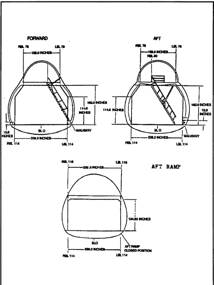
Note the dimensional data provided with the aircraft sections shown in Figure 2-15. The dia- grams depict the front of the C-5 facing aft.
Figure 2-16 shows the details of the forward cargo opening with the visor in the raised position. The side profile of the cargo floor shows the ramp in the ground loading position in the stowed posi- tion. The front view of the cargo opening shows detailed dimensions of the opening.
To ground load or unload vehicles, the pres- sure door is hinged to the ramp as a ramp extension and lowered to contact the ground. Figure 2-17 shows the aft cargo ramp in the ground loading position.
Rolling Stock Restrictions. The cargo floor is a load-carrying structure across its whole width. Vehicles can traverse its whole area and maneuver freely during loading operations. In flight, single 36,000-pound axle loads or a combination of axles weighing up to 36,000 pounds may be carried on any continuous 40-inch longitudinal length of cargo floor area between fuselage stations 724 and 1884. Figure 2-18 also shows the in-flight loading limits on other floor areas and on the ramps. The capability of the ramps and floor are such that tanks and other tracked vehicles weighing up to 129,000 pounds can be loaded and transported.
Helicopter Loading. Table 2-5 provided data for use in mission planning. For specific guidance, refer to TO. 1C-5A-9):
Figure 2-13. C-5 Schematic. to i -X a> »
c j. CAKO nucT nanas
. 71.0-
•LOil
Ul 7M
im >171 I9SI 1141 1711 •21 Ifll 20IS
•IB 12« I M 111« 1481 441 SBI BM mi T T u _J cjr® cjzo |-fl F 0 ^ » -4r
4
=4
= V V 4s III" o ^ «»”I 7M *1 7M I 04 j «44 | IBM \ IIN | I1M-| 1 Vl« | I 139» I 1411 I 1418 j 1573 I 1831 | 1724 | U04 | 1114 | 1184 1103 138) 1481 1523 H03 1175 1714 1144 1124 II 1111431 414 »24 »14 1014 I 41 1231 104 744 124 104 U Oil LBl 710 2001 |20«l j 1121 IT1 2027 2011
NOTE: Diagram Is not to scale.
USABLE CARGO AREA Length -1,726 Inches Width - 228 inches Height-156 inches k. C1,FM 55-9
FM 55-9
CARGO FLOOR ANGLES ANO CARGO FLOOR LOADING HEIGHT
2 DEQREE8 MAX N06E DOWN 4—L 1 ^ MAX NOSE DOWN
AFT KNEELED. LEVEL KNFHFD^ FORWARD KNEELED^
7B IN MAX LEVEL KNEQB)
RAMP ANGLES AND CARGO FLOOR LOADING HEIGHT AFT KNEELHJPOSmON
c5
IDESC|N »DGQ CREST
I /
O
FORWARD KNEELED POSmONIODES
7am
14 DES rr 70E3
7
Figure 2-14. Cargo Floor Angles and Loading Height.
FM 55-9 FORWARD .71 LBLTa
y
BL O IM INCHES aatoMCHES- RBL <14 MBJOMOHCS KM 114J INCHES I '»WALKWAY IBL114 AFT RBL 7« LBL7S IBM MZO INCHES IM NCHES BLO WAUOVAY QUINCHES 114 LOL 114 .11« -SKAMCHES. LBL11S r BIO nuMCHes AFT KAMP ULSO INCHES RBL 114 CUMEDPOSmON LBL114Figure 2-15. C-5 Cargo Compartment Dimenaiona.
FM 55-9 t» Æ % V* . ^ .. »» » " ** .•«-£ « Ks CARGO tï in FLOOR
\
STOWEDposmoN
GROUNDLOAONGN^
3« U1* îI •c114 N
^-186
182 tN RAMP WFigure 2-16. C-5 Visor Raised Position.
r:
\
/ J
228 IN If ir
? » ¡y
r
Figure 2-17. Ground Loading-Aft Cargo Ramp.
Figure 2-18. C-5 Flight Limitations Chart. IO i UP TO A 3,600 - LB AXLE CAN BE LOADED IN ANY 20* LONGITUDINAL AREA
UP TO A 3.600 • LB AXLE CAN BE LOADED IN ANY 20* LONGITUDINAL AREA.
T
A.
„ Av' ;
s..*p zz: 724 517 UP TO ONE 36,000 - LB AXLE OR A COMBINATION OF AXLES CAN BE LOADED SIDE BY SIDE IN ANY 40* LONGITUDINAL AREA. Y ü ul 7 -y 7 * V- ^ 1971 UP TO ONE 20,000- LB AXLE ORA COMBINA TON OF AXLES CAN BE LOADED SIDE BY SIDE IN ANY 40* LONGITUDINAL AREA. M ULTIWHEELED AXLES LOADED SIDE BY SIDE BETWEEN F.S. 1456 AND 1516 ARE UMITED TO 25,000 POUNDS COMBINED WEIGHT. 1864 UP TO ONE 20,000 - LB AXLE ORA COMBINATION OF AXLES CAN BE LOADED SIDE BY SIDE IN ANY 40* LONGITUDINAL AREA. FM 55-9C1,FM 55-9
Table 2-5. C-5 Helicopter Loading Data. TYPE/MODEL AH-1 Wings Removed AH-1 Swings Installed UH-1 UH-1 OH-6A CH-46 CH-47 Load thru Aft Doors CH-47 Load thru Fwd Doors CH-54 OH-58 OH-58 UH-60 AH-64 LOADING METHOD Disassembled Assembled/Minimum Disassembly Minimum Disassembly Disassembled Assembled Disassembled Disassembled Disassembled Disassembled Minimum Disassembly Disassembled Minimum Disassembly Minimum Disassembly TOTAL UNITS 12 5/7 7/8 11 26 3 3 2 13 22 6 6 AM
Os
0
s
Figure 2-19. KC-10 Aircraft. KC-10 CharacteristicsThe KC-10, nicknamed Extender, is a swept- wing, wide-body tri-jet with a dual-purpose mis- sion as an aerial refueler and cargo/passenger aircraft (Figure 2-19). Unit personnel, equipment, and materiel are carried on the upper deck, and fuel tanks are contained in the lower compart- ments of the fuselage.
Passenger Considerations. When planning passenger movement on the KC-10, the limiting factor will be the configuration requested or ap- proved (Appendix A). Planning weightn for pas- sengers will be 180 pounds. The KC-10 may carry up to 69 passengers (69 over water).
C1,FM 55-9
*Palletized Cargo Restrictions. The KC-10 uses a rounded cargo compartment to maximize cargo-carrying capability. It can accommodate up to 27 463L pallets. Normally, a maximum of 25 pallet positions will be authorized. Usable surface dimensions of a pallet are 104 inches long by 84 inches wide. Due to location of pallet restraint rail systems in the KC-10, the 108-inch side becomes the length of the pallet. Pallet criteria according to position, weight, and height are in Figures 2-20 and
2-21.
For ease of planning, the two pallet profiles in Figure 2-22 will simplify pallet build-up. The two pallet profiles are—
• 104 inches long x 84 inches wide x 70 inches high for pallet positions 2 through 10. • 104 inches long x 65 inches wide x 60 inches
high for pallet positions 11 and 12.
These profiles may be exceeded to maximize use of the cargo compartment. However, the max- imum profile limits (Figures 2-20 and 2-21) will not be exceeded.
Loading Guidance. The following cargo area dimensions are for general planning purposes only:
USABLE CARGO AREA Length - 1,416 Width - 218 ‘Height - 96
NOTE: Exceptions may include items configured according to TB 55-46-1 or loaded according to the aircraft loading manual.
The schematics in Figures 2-23 and 2-24, ex- tracted from DD Forms 2130-6 and 2130-7 (KC-10 cargo manifests), show the fuselage station num- bers, seating arrangements, and pallet position centers of balance.
Restraint criteria for other than netted cargo are as follows: RESTRAINT CRITERIA* DIRECTION REQUIREMENT Aft 1.5 g’s Lateral 1-5 g’s Vertical 2.0 g’s ‘See Chapter 7, Cargo Restraint.
There is no provision for floor loading unit equipment or passenger baggage. All hand-car- ried items, such as crew-served weapons, ruck- sacks, and web belts, must either fit under the airline-style seating or be palletized.
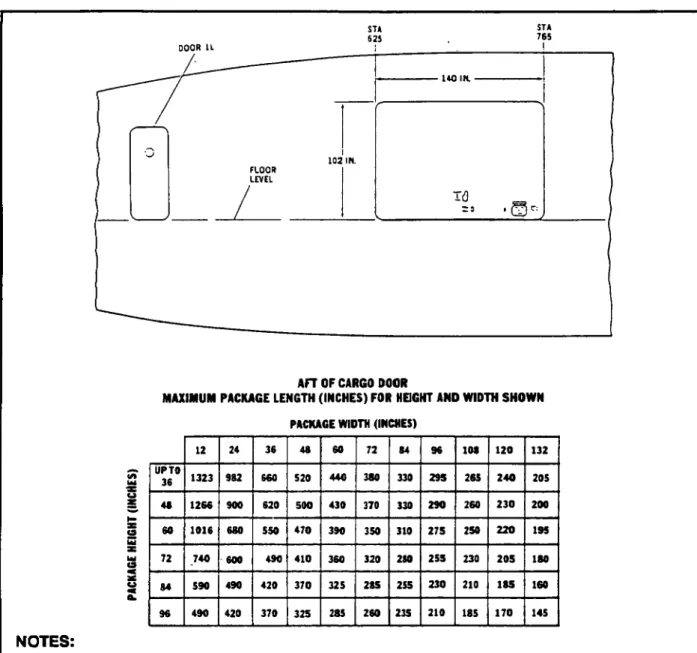
Rolling Stock Restrictions. The unique load- ing requirements and limitations for the KC-10 require special attention. Any time the use of a KC-10 for airlift is anticipated, arrangements must be made for a wide-body loader at the location. Unlike other AMC aircraft, the KC-10 does not have a ramp at ground level to roll equipment on and off. The cargo door is about 15 feet above ground level. Also, unlike other cargo aircraft, the KC-10 cargo floor cannot withstand the stress of heavy axle floor loading. Therefore, the 463L pal- lets must be used as a subfloor whenever cargo or baggage is to be loaded aboard this aircraft. Also, because of the location of the cargo door, cargo width and height must be within the cargo door limits (Figure 2-25).
There are three acceptable loading methods for use with the 463L pallet. The actual method used to load equipment dependson numerous vari- ables including allowable loading time and avail- ability of materials-handling equipment (MHE). (Wide-body loaders, K loaders, and forklifts are needed to load and move pallets.) The methods are described as follows:
• The first method is to prepalletize and se- cure cargo on individual 463L pallets be- fore loading. This method requires the least amount of time for loading.
• The second method is to place empty 463L pallets into the aircraft to create a pallet subfloor. The equipment is then driven or pushed into place and secured for flight. • The third method uses a combination of the
first two methods. The combination method provides the flexibility for last min- ute changes and requires less use of MHE. Forward (with cargo 1.5 g’s
barrier net)
Forward (without 9.0 g’s cargo barrier net)
FM 55-9 INTERIOR LINING STA 523 FUSELAGE l REFERENCE -L PLANE 18.00 TOP OF FLOOR 104.00 84.00 69.31 84 00 84.00 2.69 TYP 62..11 62.11 INTERIOR LINING X
\
96.00 74.00 16.0 MIN 70.00 70 00 18.5-IN. AISLE - 25 IN. AISLE 34.00 FRP 22.00PALLET CONTOUR B(L) , PALLET CONTOUR C (L AND R) / 14.00
TOP OF
PALLET PALLET CONTOUR A (L AND R) FORWARD OF CONSTANT SECTION
SYMMETRICAL ABOUT Ç
CONSTANT SECTION (STA 632 TO 1610)
PALLET CONTOUR KEY
25
(A) IB) (0) <H) («> (■) IN)
I I i—i—i——r lili 84.00 84.00 1 Z (AA) (B8) 76.31
54.81 (CC) (Do) (EE) (Er) (GG) (HH) (II) (««) (ID mm ("Ni (“) <««)
50.88 INTERIOR LINING STA 1826 \ INTERIOR \ X ^ LINING STA 1935 88.75 85.50 16.0 MIN 16.25 TOP OF ROLLERS 17-IN. AISLE 28.50 44.00 FRP FRP 7
\
PALLET CONTOUR D (L AND R) '—ROLLER HEIGHT = 1.75 AFT OF CONSTANT SECTION
SYMMETRICAL ABOUT Ç
PALLET CONTOUR E (L) AFT PALLET
96.00
tz-z
•(z jaens) suojiunSyuoo
9|S!V pue wnouiao tailed 1.2-2 ainBy
OHVMNOd MIX001 S3K3NI »8 0 ZL ll n
tz
£ 09 09 frt 8» X 9t X 09«
6« IK Wl 01*iru
ODiHf\
m 018 imres
S¿18irte
016 88us 21 S¿ 0 98 b— VZ2 1179G
«) (Wl|(tt<)| il n I n (wi (re unía tx) M mui <11 niu » i I l.l I r-rB i i a — i LrJ I I ii) du n U n 11 (t> i11 i i r i i i I;I i -t-> j i u r31 ~ r ’ÁJxanoiMODiniYd isi BOiei (D •itiomciT/OTi own <o)<
l/Wl rtMHi l O) <
isi nu Hi z (a)—■ Hi QttVlI ®—
tro« FM 55-9 S1H3NI 3 3 »3 5 ! I 1 n »i s - W N S3H3NI o2 N M »? , I 3» ï I
I-fl
SX ^ «< s - 5°Figure 2-22. Pallet Profiles.
FM 55-9
THIS PAGE INTENTIONALLY LEFT BLANK
Cl,FM 55-9
KC-10A MK CONFIGUIUTIOM TS SUIS 17-PUUT COMPARTMENT ARRANGEMENT
LU MR LU M.0 LU S7.I OQ U 0.0- RU S7J RU MJ RU M 3
>CAttO PCO» I4C I 490 I SM I 970 I
470 SIO SSO 590
690 I 730| 7!
439 610 6S0 H 790 I 830 Israjon 770 810 832 679
SCALE: 1/4 INCH = 3 FEET
C O CARGO PALLET POSITIONS
1011 1120 1229 13M X 1447 1556 1665 1774 1883 5R 6R a 7R 7L 8L 9R 10R 101 I I I HR m 9301950 I 990 I 1030 I 1070 I 1110 I 1150 I 1190 | 1230 | 1270 | 1310 I 1350 I 1390 I 1430 I 1470 I 1510 I 1550 | 1590 I 1630 | 1670 I 1710 | 1750 I 1790 I 1830 I 1670 ! 1910 11937 910 939 970 1010 1050 1090 1130 1170 1210 1250 1290 1330 1370 1410 1450 1490 ISM 1570 1610 1650 1690 17M 1770 1610 1950 1990 19M AR0 STATION m I3L
SCALE: 1/4 INCH 3 FEET
NORMALLY NOT USED FOR CARGO
CRYOGENIC VENT
NOTE:
PALLETS 5 THRU 10 LEFT ANO RSHT MAXR8UM HEIGHT 96" FROH U 0.0 TO U 64.0 70' FROM U 64.0 TO U 98 0 PALLETS II THRU 12 LEFT ANO REHT NAIMUM HECHT FROM 81 0.0 TO U 57.0 FROM 9L 57.0 TO U 86.0
MAXIMUM AFT ROOT TANK FUEL
Figure 2-23. KC-10 Schematic—17 Pallets Configuration (Code D).
SCALE: 1/4 INCH = 3 FEET
KC-10A IAK CONFIGURATION 16 SEATS 23-PALLET COMPARTMENT C.6. CARGO PA an POSITIONS RU M.0 OQ RU 64.0 RU 37.0 U 0.0- □ LU 57.0. LU 64.0 LU M 902 1011 1120 1229 13M 1447 1556 1665 1774 1863 3R 3L 4R 4L 5R 6R 7R 8L 9R 91 108 10L . «Otto »M« 141 . 113 470 I 510 I 550 I 590 I OO I 676 I 710 I 750 439 490 5M 570 610 ' 650 ' 699 790 I 830 I 870 I 910 I 950 I 990 I 10M I 1070 I 1110 I 1150 I 1190 I 1230 I 1270 I 1310 I 1350 I 1390 I 1430 I 1470 | 1510 ! 1550 I 1590 I 1630 ! 1670 I 1710 I 1750 I 1790 ! 1830 I 1870 I 1910 11937 770 810 850 890 9M 970 1010 1050 1090 1130 1170 1210 1250 1290 13M 1370 1410 1450 1490 1530 1570 1610 1650 1690 17M 1770 1010 1850 1890 1930 I2R 11R ARO STATION m I3L 111 1946
SCALE: 1/4 INCH 3 FEET
NORMALLY NOT USED FOR CARGO
▲ CRYOGENIC VENT NOTE:
PALLETS 2 THRU 10 LEFT AND RIGHT MAXIMUM HECHT 96" FROM U 00 TO BL 64 0 70" FROM 81 64.0 TO U MO PALLETS 11 THRU 12 LEFT AND RCHT MAXIMUM.HECHT M" FROM U 00 TO 8157.0 28" FROM BL 57 0 TO 81 86 0
MAXIMUM AFT 800Y TANK FUEL
Figure 2-24. KC-10 Schematic-23 Pallets Configuration (Code B).
Cl ,FM 55-9 DOOR U STA STA 765 o 25 140 IN. 102 IN FLOOR LEVEL ÚJ = 3 1 f-.'l T:
AFT OF CARGO DOOR
MAXIMUM PACKAGE LENGTH (INCHES) FOR HEIGHT AND WIDTH SHOWN PACKAGE WIDTH (INCHES)
<s « 3C o UP TO 36 60 72 84 96 12 24 1323 1266 1016 740 590 490 982 900 680 600 490 420 36 48 60 72 620 550 490 420 370 520 500 470 410 370 325 430 390 360 325 285 380 370 350 320 285 260 84 330 330 310 280 255 235 29S 290 275 255 230 210 108 120 132 285 260 250 230 210 185 240 230 220 205 185 170 205 200 195 180 160 145 NOTES:
1. Lengths are determined for packages In contact with top of rollers in cargo loading system, allow- ing two-inch clearance from airplane interiors.
2. For dimensions not found on this chart, refer to the next higher dimension.
* 3. Packages exceeding the lengths allowed by this chart will not be planned for airlift without the approval of the TALCE.
Figure 2-25. KC-10 Package Size Chart-Cargo Loaded Aft of Cargo Door.
The pallet profile limitations also apply to wheeled equipment. In addition, allowable axle weights and axle separations (Figure 2-26 and 2- 27) must not be exceeded. (Exceptions are al- lowed according to T.O. lC-10(K)A-9. Section V
outlines specific loading procedures for items that do not fit within general loading criteria or require a waiver of the aircraft limitations; for example, M-35A2 2 1/2-ton cargo truck [without winch], Figures 2-28, 2-29, and 2-30.)
Figure 2-26. Cargo Loading Data. ■P ro to COlitPARTMIN I LOAD
LIMIIAIKMK
©
MAXIMUM AXtí AUD Wlltlt WtlOIITÎ FOnVDUCU&PNIUMAUC MfitS (L8flPAUtl
POSITIONVCOMPARIMCNT
un on niant ntt inmct DATA
MAXIMW FLOOR LOADWO ILDS/LINtAR FOOT)
MAXIMUM TOTAL COMPAnlMtnT
LOAD {Mi) i£Fr on niaiir FLIGHT
FLOOR ARCA tSQUAFK rctii VOLUME ICUflIC rtti) FOnnARO LIMIT STATTON AFT LIMIT S1ATKIII COMPAfi^MCHIS tSiOCWAlL MARKinaS) rALLIT POSKIOUS laooFi MARKinasi MAXIMUM •int HAXIM1JM AXLl
CINWOIO aie orr nnnr
575 3» 630 4» 736 DOS 6.300 3.000 6.000 664 468 BID 730 432 738 10.000 6.500 1000 6000 2.750 4.3na 793 46« 719 648 452 73« T 0.000 6,500 3.000 2,250 4.600 468 848 »7 6,300 902 718 MO 2.750 4,300 937 1.066 1.011 468 738 6.SD0 7.750 4.300
1,120 468 IM« 1.173 IBS 6.500 2.400 4AI00
1.264 IJ29 4(8 1.173 432 10.000 1.600 3,700 1.338 468 1284 IJ93 .437 10.000 1.600 1200 .447 4(8 1,393 1307 1,152 000 10.000 1,600 >200 6(8 1.302 1000 1,35« 1,611 432 186 0.000 0.000 000 7.000 4.001 10.000 1.663 195 (I .720 452 MM 10X100 UM 6.000 7.000 4.000 1.823 452 (.500 1,774 393 1,770 738 10.000 3.000 (.000 2JOOO 4.000 1,937 (.300 1.881 171 IJ29 43? 738 10.000 3.000 6,000 7.000 4.000 NOTES:
1 Comparcnent 13(H) pertainn to left aide only.
2 Wheels must be AB inches apart. These
allowables are for any location on the pallet. Treat dual wheels as one wheel.
3 Only cor.priiBsible cargo should bo loaded in the first position occupied aft of the cargo harrier net.
FM
FM 55-9 (ftSTAHCS ESTWæa vwsaji. (CiCKIS} 10 U 12 13 14
ALLOtBÂftBU Aîtt£ üv3QHT OM KCU-S/S PAUüT§. A<Li^fiSLii<^iasair(PeyK33)
□□□□
nn□□
0 c B C- 2 3 4 5 •e ts□
□
n
ai vS□
CO
□
CD
M I ) 7 8 9 et oâ ea e9 lâ <0 -3 rJ3^
10 11 12 13 ni ai ai •0 >6 «0 -J -î ,-J ,J 2^50 2305 2.362f
2400 2.460 1.600 T5ST 2,419 i4>3 2,531 2387 2320 2330 2340 2700 ¿760 1330 U 20 ■SHS- 2.050 TTST ¿100 ¿150 1.900 ¿200 2350 135a" 15 ¿644 2320 1380 ¿350 IT 17 18 TffîT ¿880 1320 ¿400 ¿755 ¿940 1360 ¿450 ¿312 3300 ¿000 2300 19 20 21 22 23 24 25 26 27 ¿8S9 ¿0S0 2.040 2.925 2.931 3.037 ¿120 ¿080 2.550TS5<r
¿180 ¿120 2350 ¿094 3240 2,160 ¿700 3.150 ¿300“ssr
2200 2240 ¿750 2300 HÔT 3262 ¿319 3420 2280 ¿850 3.430 ¿320 ¿540 ¿360 ¿900 ¿950 23 29 30 ¿375 ¿431 ¿487 ¿600 ¿400 ¿660 ¿440 ¿000 T55T 3.720 ¿480 ¿100 31 32 33 ¿544 3.600 ¿780 3340 2.520 3.150 ¿560 ¿200 3.656 ¿900 ¿600 3250 34 35 36 3.712 3.960 ¿640 ¿769 4.020 ¿680 ¿825 4.080 ¿720 ¿300 ¿350 ¿400 37 38 39 ¿881 4.140 3.938 4200 ¿760 ¿800 3.450 ¿994 4260 ¿840 ¿300 3.550 40 41 42 1.050 4.320 4.105 '4.380" 4.162 4.440 ¿880 3.600 1320 TEST ¿960 3.700 43 4.219 4300 ¿000 ¿750 44 4275 4.560 ¿040 ¿500 3350 45 46 47 4331 4.620 ¿080 4.387 4.630 3,120 4.444 -asar 4.740 4.800 ¿160 3200 3.900 ¿950 4.000 AXLEJLOOTS 1. U6EILESgSaC?TR3A9©aWfKSEU£»SE. a. CHECÄEOTO 780.^70 SSieoaiNEftOSURATi TREAD SH&SMSfflM.& TREAT OLKLVÏKSELS AS OMI
4. TKE STRUCTURAL Ü.OÄD3MGI HECHTS AND ZONE IIOADCX!© LCa(T8 KU8T ALfâ BE CaSERVEO. a FOaaKQLÊWHEaâ USE ÔÎŒ-HA!LF OP VALUES USTIHJ ABOVE. USE &JKCH UKE VÍÍMSW1VHEEL8 AfŒ UES8 TOAN 0 WCHES ARA HT (LATERALLY 03 LOM-
©nruKmLY).
m
Fcgw® 2-27. Vetiide ÂKle Weôghl UmWtons.
FM 55-9
y
r» <r CM CM K O U £S
O O O ce V oc kO C oc IA CM en m tr CM CM CC O OFigure 2-28. Loadable Locations for M-352A Caigo Truck.
FM 55-9 )(
K
li
|[II
ï
!
Il
K
-ChL
6 AIRPLANEFigure 2-29. Position of M-35A2 Cargo Truck (Centerline-Loaded).
FM 55-9 15 14
¡ÏÏTTT
B '-i
Il Il II IIï'i
nn • in -4--H-H pq-—,T+-'Hï l I
1«I ! ' I!
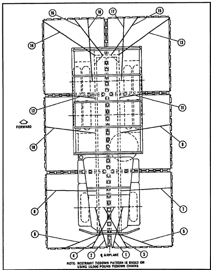
Il I |l ^ Ü I 'I Vt 2 » lÜSî KÍ KH ■tt <_> uu FORWARD un O 1? Ä M nu «III hd 's® m I III I C AIRPLANE (1NOTÉ RESTRAINT TIEDOWN PATTERN IS DASED ON USING 10,000 POUND TIEDOWN CHAINS.
Figure 2-30. Plan View-Tie-Down Pattern for M35A2 Cargo Truck (Centerline-Loaded).
FM 55-9
Figures 2-31 and 2-32 show an example of a example of allowable lateral loading limits, total CG problem. Figures 2-33 and 2-34 show an
K Sï S. as o — u « A/
□
- it ar _ Se * ¡II il
äs »s I =3 ^3jr
VE AA r Y 37
ri
o
Q a ï ~ s .si Í. - i S 2Figure 2-31. Total CG-Sample Problem 1 (Sheet 1).
FM 55-9 PALLET POSITION ITEM ARM (STATION NO.) WEIGHT 08) [MOMENT v ARM X WEIGHT] 10,000 / I3MN) 12LA12R(M4i) 11LA UR(l-L) lOLAlOR(K-K) «.IflR(J-J) 8LASR(H-H) 71A7R(0-G) «LASR(F-f) SLASR(E-E) 4lA4R(DO) 3L ASR(C-C) 2LA2R(8-B) HCU-6/E PALLET AGETRACTOR MHU-S3A/E TRUCK TWO HCU4/E PALLETS (7,100 A 7^00 LBS) TWO HCU-S/E PALLETS (1,0008 6^800 LBS) AM32A-C0 OEM SET MHU-12M TRAILER MHO-ISM TRAILER MB-4 TRACTOR TWO HCU-6/E PALLETS (6,400 A ^500 LBS) TWO HCU-6Æ PALLETS (lOOOA^SOOLBS)
TWO HCU-O/E PALLETS (3,000 A 2^00 LBS 18S3LO 1774.0 16610 15510 1447.0 1936^) 12210 11204 101LO 9024 7934 6844 1100 5,100 7,693 11300 14400 1410 S4OO 1600 11,720 U900 7400 1500 1.14163 90174 149048 248168 Z141.56 $9106 68124 515.20 1,16449 1,16158 570.96 37640 TOTALS 100¿23 U94162 NOTESi
L THIS TABU IS USES FOR CALCULATING THE 11 OF THE CARGO LOAD AND NOT FOR SEQUENCE OF ACTUAL LOADING OPERATIONS.
I TOTAL WAO CAL X 10,000.12tt7
Figure 2-32. Sample Problem 1 (Sheet 2).
FM 55-9
TWO VEHICLES ARE TO BE LOADED AS SHOWN BELOW ON PALLETS LOCATED IN PALLET POSITIONS 4L, 4R, 5L, AND 5R. CALCULATE THE LOAD UMITS.
4 FORWARD 5|i
L_J64
*r-130
25
CP
64
1. APPUED LOAD - PALLET POSITION 4R AXLE WEIGHT = 4,400 POUNDS PALLET POSITION 5R AXLE WEIGHT = 2,850 POUNDS PALLET POSITION 4L AXLE WEIGHT = 4,400 POUNDS PALLET POSITION 5L AXLE WEIGHT = 2,850 POUNDS 2. DISTANCE BETWEEN LOADS - ALL AXLE TREADS = 64 INCHES
BOTH WHEEL BASES = 130 INCHES LATERAL AXLE SEPARATION = 25 INCHES
3. ALLOWABLE LOAD - PALLET POSITION 4R = (AXLE) PALLET POSITION 4L = (AXLE)
PALLET POSITION 5R = (AXLE) PALLET POSITION 5L = (AXLE) ADJACENT PALLET = (AXLE)
Figure 2-33. Sample Problem 2 (Sheet 1).