1 Corresponding Author. Mail. [email protected]
Tell: +989124148841
Sensor less control of Non-Ideal back-EMF permanent magnet
synchronous Motor based state space control and sliding mode based
observer
Samane Sadooghi, Dr Abolfazl Halvaee Niasar
Department of Electrical Power Engineering, Kashan University, Faculty member of Kashan University of Technology
Received: 12, September, 2017 Accepted: 17, January, 2018 Online Published: 09, Jun, 2018
Abstract
The permanent magnet synchronous motors are mechanically very robust and powerful, which makes it possible to achieve high speeds using these motors. The air gap in these motors is very small, so the effect of the armature reaction is significant and noticeable. This feature also makes it possible to control this machine in constant torque regions and to reduce the flux. For a synchronous permanent magnet motor, in some cases, the need to control the motor speed or the motor position is very important. The controller of these motors plays a very important and effective role in controlling the speed and motor position. It causes that the use of intelligent and adaptive controllers would be considered more. In this study, the state-space control method is used to identify the system conversion function and the controller with sliding mode observer is used to identify the disturbances of the system. Also, in the configuration of the system, a three-level converter of the voltage source is used to control and change the voltage and frequency. The output includes a designed constant voltage that in this way, the process of speed variation with a much higher dynamic response to a faster and better response than other control methods.
Keywords: permanent magnet synchronous motor, state-space control mode, sliding mode observer, SVPWM switching
1. INTRODUCTION
In recent years, the permanent magnet synchronous motors have been widely used in the industry with many advantages such as high efficiency, low inertia, torque ratio to high current, and power ratio to high weight. These motors do not require rotor windings compared with the induction motor. Thus, their efficiency is higher than the induction motor. The choice of permanent magnetism for the motor is influenced by factors such as engine efficiency, weight, volume, efficiency, and material and production costs. The ability of machining the material, tolerance and easy-handling of permanent magnet material can have a significant impact on production costs.
With the development of permanent magnetism technology electronic science, the power of using Permanent Magnet Linear Synchronous Motor (PMLSM) has become widespread in various areas of the industry, especially in high precision control servers [1].
In many studies, the main reason to use these motors is high output, torque and very high power density. Due to variation in load and mechanical friction, uncertainty in the model of proposed systems in many researches are high, which would have adverse effects on the accuracy of the control system. So far, various methods have been proposed to reduce and eliminate the effects of these uncertainties. In the case of a proportional-integral controller which controls the motor with coupler current, due to the constant of the coefficients, the control process will be slow along with overshoot [2].
It is worth noting that these traditional methods are not sufficiently flexible, they often have high computational costs. Today, smart methods are widely used, and
although they are structurally simple, they provide relatively accurate results. In some studies, the
Classifier that is based on the multilayer perceptron neural network is used to determine the different operating conditions of three-phase induction motor. These conditions include an internal short-circuit (loop-to-loop), a stator winding, dynamic centrifugal force of the rotor, or both. [3, 4].
Also, statistical parameters are used as an input feature space and the main component analysis is used to reduce the input dimensions. In the studies to identify the disturbances in the system, the fuzzy-Bayesian change point detection method has been used. To perform this research, we have used two steps in this paper: in the first step, the initial data are converted by fuzzy clustering, which can be approximated by beta distribution; in the second step, the algorithm has been used to detect change point in converted time series, which has been produced by the first step with a specific distribution. [5]
In another study, the researchers believe that as stator error and the disturbances in the system have no clear signals in the current spectrum, it is necessary to use the other methods instead of the traditional spectral analysis method. For this reason, the fuzzy logic method has been used on the phase current range [6].
The uses of comparative reference model and control with sliding mode observer in PMLSM motors have been considered. The method of comparative reference model is not only used to adjust the parameters of the system model, but also to control the parameters of the controller. Generally, identification of model parameters in MARC is necessary [7].
2 surface. However, the chattering phenomenon will have undesirable effects on the system [8].
With the development of special electric vehicle control techniques, these machines have found suitable industrial applications. These machines have magnetic saliency. In other words, vertical axis inductance is more than direct axial inductance, so that with special arrangements in the design of this machine, the vertical axis inductance can be increased up to five levels more than the inductance axis [9]
The magnetic saliency of this machine makes it possible to use an inverter with a lower switching frequency to control the machine. In addition, magnetic resonance has a direct relation with the maximum torque produced by the machine. In addition, permanent magnet synchronous motors have more efficiency and power than other motors [10].
Due to the sensitive application of these motors, their maintenance is essential. While avoidance of errors is not easy in engineering systems [11].
Over the past decades, attempts have been made to detect errors in electrical devices and to respond best to them. Therefore, accurate and rapid diagnosis of error seems very important. Due to the rotor’s design, PMSM poles can be designed in a smooth or saliency mode. Motors with smooth pole have a cylindrical rotor and therefore have a uniform air gap. Motors with saliency pole have variable air gap. In these motors, the air gap is very small [12].
Therefore, the effect of armchairs reaction is remarkable. This feature also makes it possible to control this machine in constant torque areas and to reduce the flux.
2. Modeling of permanent magnet synchronous motor
In order to design a position controller for detection of an error, the permanent magnet synchronous motor must first be properly modeled. There are many researches on PMSM modeling and calculation of their parameters. In most of the proposed models, it is required more than data which is in access that its result is more memory occupation and prolongation of computer program execution time. This model focuses on main frequency components. The magnetic circuit is assumed to be linear, the stator windings are distributed as sinusoid, and it is assumed that the magnetic field along the rotor axis is evenly distributed.
𝑑𝑖𝑑 𝑑𝑡 =
1
𝐿𝑑 (𝑣𝑑− 𝑅𝑠𝑖𝑑+ 𝑤𝑒𝐿𝑞𝑖𝑞) (1) 𝑑𝑖𝑞
𝑑𝑡 = 1
𝐿𝑞 (𝑣𝑞− 𝑅𝑠𝑖𝑞+ 𝑤𝑒𝜓𝑝𝑚) (2) 𝑑𝑤𝑚
𝑑𝑡 = 1
𝐽 (𝑇𝑒𝑙− 𝑇𝐿) (3)
𝑇𝑒𝑙 = 3𝑁𝑝
2 [𝜓𝑝𝑚 𝑖𝑞+ (𝐿𝑑− 𝐿𝑞) 𝑖𝑑𝑖𝑞] (4) In these relationships, Lq and Ld are the inductances of the q and d axes. Rs is as stator resistance, we as motor electric speed, j as the moment of motor and load inertia,
ψpm as permanent magnet flux and Np as the number of pair poles. In addition, TL is the turbulence torque which is not considered in the final modeling. The above equations clearly show that the control system of the permanent magnet synchronous motor is described by a series of nonlinear equations, even if the electric and mechanical parameters of the motor are assumed as fixed.
3. Sliding mode theory
This control is one of variable-structure control types that controlling variable structure is sometimes known as a sliding mode observer due to the resistance specifications against with disturbances and uncertainties [21]. The basis of this method is that, for example, in a second order system, when the system-defined variable of the system slides from two sided to the surface, it will remain on that surface as soon as it reaches the slider surface, which, as a result, moving on this surface reduces the order of the system to one. This surface also has specifications that are resistant to disturbances, because the behavior of the system on this surface only depends on the slope of this surface [14]. Moving on sliding surface as it remains on it and moving over to the point of equilibrium of system is called sliding mode motion. The surface that the system switches over after reaches and remains on it and moves to the equilibrium point over time is called as a sliding surface [13].
1.3. Basic equations
derived from the Park's equations will be obtained by using the two components 𝑢1𝑑 = and 𝑢1𝑞=.
Figure (1): Principles and design used in system input and output with PID controller
The voltage equations and linkage flux in linear permanent magnetic synchronous motor are based on the two-axis theory as the following d-q relations.
𝑢𝑑= 𝑅𝑠𝑖𝑑+ 𝑝𝜆𝑑− 𝑣𝜆𝑞 (5)
𝑢𝑞= 𝑅𝑠𝑖𝑞+ 𝑝𝜆𝑞− 𝑣𝜆𝑑 (6)
𝜆𝑑= 𝐿𝑑𝑖𝑑+ 𝜆𝑃𝑀 (7)
𝜆𝑞= 𝐿𝑞𝑖𝑞 (8)
Where the voltage of the armature windings in direction of uq and ud and axes of q, d, Ld and Ld are inductances in line with q and d. λd and λq is linkage fluxes in direction of d and q axes. Rs is stator resistance and λPM represents the permanent magnetization stimulation field for stator. If the current internal of the loop PMSM is zero (i_d = 0), then the current vector is perpendicular to the stator field, and the torque equation will be as in relation to (9). 𝐹𝑒= 3𝜋 2𝜏 𝜆𝑃𝑀𝑖𝑞 (9)
Fe is the electromagnetic torque and τ is the pole angle. Tt can be seen in relation (9) that the torque depends only on iq. So the equation of motion is expressed as relation (10). 𝐹𝑒= 𝐾𝑓 𝑖𝑞 = 𝐹𝐿+ 𝐷𝑉 + 𝑀 𝑑𝑣 𝑑𝑡 (10)
In this case, V is the velocity of the moving part, Kf is the electromagnetic torque coefficient, D is the friction coefficient, FL is load turbulence and M is the mass of the moving part. 4. State-space control method control diagram block is provided for controlling the current through the state-space in Fig. 2[15]. Figure (2): State-space diagram block for current control Si is the block of the adjusted system, which is expressed on Equation (8). Ûn shows the disturbances in the system, and Scm represents the block of the control system that here the control is based on the voltage source [23]. Ri is the current compensator. In this case, equations (11), (12), (13) and (18) are as following: 𝑑𝑖𝑞 𝑑𝑡 = −𝑅𝑖𝑞+ 𝐿𝜔𝑖𝑑+ 𝑢𝑞− 𝑢𝑒𝑞 = −𝑅𝑖𝑞− 𝐿𝜔𝑖𝑑+ 𝑆𝑞 𝑢𝑑𝑐 − 𝑢𝑒𝑞 (11)
𝑐 𝑑𝑢𝑒𝑑 𝑑𝑡 = −𝑖𝑧𝑞+ 𝑐𝜔𝑢𝑒𝑑 + 𝑖𝑑 (12)
𝑐 𝑑𝑥4 𝑑𝑡 = −𝑖𝑧𝑞− 𝑐𝜔𝑢𝑒𝑑 + 𝑖𝑞 (13) In these relations, Sd and Sq are switching functions in direction of d-q axes and the impedance z is related to three-phase load, and udc is related to DC voltage. If we have:
𝑥1= 𝐿𝑖𝑑 , 𝑥2= 𝐿𝑖𝑞 , 𝑥 3= 𝑐 𝑢𝑒𝑑 , 𝑥4= 𝑐 𝑢𝑒𝑞 (14)
𝑑𝑥1
𝑑𝑡 = −𝑅𝑖𝑑+ 𝐿𝜔𝑖𝑞+ 𝑢𝑑− 𝑢𝑒𝑑= −𝑅 𝑥1
𝐿 + 𝜔𝑥2+
𝑆𝑑𝑢𝑑𝑐− 𝑥3
𝑐 (15)
𝑑𝑥2
𝑑𝑡 = −𝑅𝑖𝑞− 𝐿𝜔𝑖𝑑+ 𝑢𝑞− 𝑢𝑒𝑞= −𝑅 𝑥2
𝐿 − 𝜔𝑥1+ 𝑆𝑞𝑢𝑑𝑐− 𝑥4
𝑐 (16)
𝑑𝑥3
𝑑𝑡 = −𝑖𝑧𝑑+ 𝑐𝜔𝑢𝑒𝑞+ 𝑖𝑑= −𝑖𝑧𝑑+ 𝜔𝑥4+ 𝑥1
𝐿 (17)
𝑑𝑥4
𝑑𝑡 = −𝑖𝑧𝑞− 𝑐𝜔𝑢𝑒𝑑+ 𝑖𝑞= −𝑖𝑧𝑞− 𝜔𝑥3+ 𝑥2
𝐿 𝑑𝑥4
𝑑𝑡 = −𝑖𝑧𝑞− 𝑐𝜔𝑢𝑒𝑑+ 𝑖𝑞= −𝑖𝑧𝑞− 𝜔𝑥3+ 𝑥2𝐿
(18) In controlling state-space, turbulence involved in the
system and its sizes in the compensator block are used to compensate the poles created in the system conversion function which has dynamically better stability [18]. Initially, the open loop state of mode function is used and then, appropriate regulators are fitted to compensate these poles in the conversion function after determining the poles of the system. The basis of using state-space control method is based on the voltage source (VSI) in frequency of the inverters. A
5. Sliding mode observer
The sliding mode estimator is a suitable method for estimating in nonlinear systems such as permanent magnet motors [17]. This estimator is not sensitive to variations in parameters as well as disturbances. Since, one of the main specifications of sliding mode observer is its resistance against uncertainties, therefore in designing this observer, the elements can be ignored that are dependent on state variables and only sample the system output.
1.5. Sliding mode observer layout
This observer has special specifications that enable it to measure sliding motion for the error between the outputs and make output of the observer. This ability ensures that the observer accurately shows a series of static statistics that fits the actual output of the device. The BLDC motor formulas are expressed using sliding mode observer in the control of the permanent magnet motor with consideration of current equations in the stator dual-axis device as following relations (19) and (20).
𝑖𝛼= − 𝑅𝑠 𝐿𝑜 𝑖𝛼+
1 𝐿0 𝑢𝛼 −
𝜆𝑚
𝐿0 𝑤𝑟𝑐𝑜𝑠 𝜃𝑟 (19)
𝑖𝛽= − 𝑅𝑠 𝐿𝑜 𝑖𝛽+
1 𝐿0 𝑢𝛽 −
𝜆𝑚
𝐿0 𝑤𝑟𝑠𝑖𝑛 𝜃𝑟 (20)
The back-emf voltage in direction of βα axes is expressed as following: 𝑒𝛼= 𝜆𝑚 𝜔𝑟 𝑐𝑜𝑠 𝜃𝑟 (21)
𝑒𝛽 = 𝜆𝑚 𝜔𝑟 𝑠𝑖𝑛 𝜃𝑟 )22)
𝑒𝛼° = − 𝜔𝑟 𝑒𝛽 (23)
𝑒𝛽° = − 𝜔𝑟 𝑒𝛼 (24)
Sliding mode observer inputs are determined by using the current conversion and the output voltage of permanent magnet synchronous machine on the βα axis according to the relation (25) [ 𝒇𝜶𝜷𝟎 ] = [ 𝑻𝜶𝜷𝟎 ] [ 𝒇𝒂𝒃𝒄 ] ⇒ [ 𝒇𝜶 𝒇𝜷 𝒇𝟎 ] = 𝟐 𝟑 [ 𝟏 −𝟏 𝟐 𝟎 𝟏 𝟐 √𝟑 𝟐 𝟏 𝟐 −𝟏 𝟐 −√𝟑 𝟑 𝟏 𝟐 ] [ 𝒇𝒂 𝒇𝒃 𝒇𝒄 ] By defining the vectors in the reference abc, βα and dq0, we will have:
𝑺
𝒂𝒃𝒄= [𝑺
𝒂𝑺
𝒃𝑺
𝒄]
𝑻(26)
𝑺
𝜶𝜷𝟎= [𝑺
𝜶𝑺
𝜷𝑺
𝟎]
𝑻(27)
𝑺
𝒅𝒒𝟎= [𝑺
𝒅𝑺
𝒒𝑺
𝟎]
𝑻(28)
S is related to the components and voltage and current and flux (λ) vectors. S0, is in zero sequence. Using these equations, required conversions are performed on the dq0 axis. Figure (3) is conversion block of current output (iabc) and output voltage of synchronous machine (vabc) to convert in the device dq0
Figure (3): Equations for converting in a rotary axis device (dq0) Now, by considering the following equations, we can make necessary conversions in all modes βα and dq0. (Trt is the component and necessary matrix to convert in all states.)
𝑇
𝑟𝑡= [
𝑐𝑜𝑠 𝜃
𝑠𝑖𝑛 𝜃
0
− 𝑠𝑖𝑛 𝜃
𝑐𝑜𝑠 𝜃
0
0
0
1
]
(29)
We expand equation (29) as equation (30):
𝑇
𝑒𝑐𝑘= 𝑘 [
𝑐𝑜𝑠 0
𝑐𝑜𝑠 (
2𝜋3
) 𝑐𝑜𝑠 (
4𝜋
3
)
𝑠𝑖𝑛 0
𝑠𝑖𝑛(
2𝜋3
)
𝑠𝑖𝑛(
4𝜋
3
)
𝑎
𝑎
𝑎
]
(30)
𝑇
𝑒𝑝=
𝑘 [
𝑐𝑜𝑠 𝜃
𝑐𝑜𝑠 (𝜃 −
2𝜋3
)
𝑐𝑜𝑠 (𝜃 −
4𝜋
3
)
−𝑠𝑖𝑛 𝜃
− 𝑠𝑖𝑛(𝜃 −
2𝜋3
) − 𝑠𝑖𝑛( 𝜃 −
4𝜋
3
)
𝑎
𝑎
𝑎
]
(31)
{
𝑇
𝑒𝑝= 𝑇
𝑟𝑡𝑇
𝑒𝑐𝑘𝑆
𝛼𝛽0= 𝑇
𝑒𝑐𝑘𝑆
𝑎𝑏𝑐𝑆
𝑑𝑞0= 𝑇
𝑟𝑡𝑆
𝛼𝛽0= 𝑇
𝑒𝑝𝑆
𝑎𝑏𝑐(32)
Figure (4) : Conversion of dq to βα components
The sliding mode controller is designed with the following dynamic relation:
𝑢̂ = 𝛼 𝑤̇ + 𝑤𝑟̈ + 𝑐 𝑒̇ + 𝜆𝑒 + 𝑘 𝑠𝑔𝑛 (𝑠)̈ (33)
𝑒 = 𝜔𝑟− 𝜔 (34)
𝛼 = 𝑘𝑖
𝑘𝑝 (35)
The function sgn is considered as the relation (36)
{𝑠𝑔𝑛 (𝑠) = +1 𝑖𝑓 𝑠 > 0
𝑠𝑔𝑛 (𝑠) = −1 𝑖𝑓 𝑠 < 0 (36)
Considering equations (35) to (36) and equations for βα, the system of simulated sliding mode control is based on Fig. 5.
Figure (5): sliding fashion control system
6. Current Control
This method includes P and PI and I regulators that in order to design it, the system function is in open loop-state, and one of the problems is that standard regulators can compensate a pole or a pair of poles while the regulated system has more than a pole in conversion function. GpE1 (S) consists of a converter part (a three-level converter of voltage source with a small time constant(𝑻𝒑𝑬𝟏 (𝑺))) which (S) 𝑮𝑹𝟏 current regulator should be designed based on this.
We will have by using equation (37):
𝒊𝟏= −
𝑼𝟐
𝒓𝒔𝒄+𝒋 𝒇𝟏 𝒙𝒔𝒄+𝒔 𝒙𝒔𝒄𝒘𝒏+
Û𝒏
𝒓𝒔𝒄+𝒋 𝒇𝟏 𝒙𝒔𝒄+𝒔 𝒙𝒔𝒄 𝒘𝒏 (37) In this case, Ûn is disturbances and the value of 𝒇𝟏 is in perionic ratio. Accordingly, value of the block conversion function of the diagram 𝑮𝒊𝟏 (𝒔) can be obtained:
𝑮𝒊𝟏 (𝒔) = 𝒊𝟏 𝒖𝟐
− 𝟏 𝒓𝒔𝒄
𝟏+( 𝒋 𝒇𝟏 𝝎𝒏+𝑺 ) 𝝎𝒏𝒓𝒔𝒄 𝒙𝒔𝒄 (38)
𝑮𝑷𝑬 (𝒔) = 𝒖𝟐 𝒖𝒄𝒎=
𝑼𝑫𝑪
𝟏+𝑺 𝑻𝒑𝑬𝟏 (39) The reference values of the powers are calculated and compared and is established to hysteresis controllers. The results of outputs are established by hysteresis comparators with the position of stator flux as input to the switching table. Then the proper voltage vector is determined by the switching table and the signals are applied to the inverter.
7. The general structure of the converter
The converter study has increased with the development of emerging technologies, such as multi-level converters [16]. These newer topologies, among other advantages, essentially increase the power and voltage employed by the converter. The state-space control strategy for machine-side convertor is reviewed. The general structure of the three-level converter is presented in Fig. 6:
Figure (6): The general structure of the converter used in the research
The DC link voltage is driven by two capacitors C1 and C2 that are connected in series. The capacitance of the two capacitors is equal to each other and there is a neutral connection point (n) in the middle. Switching states for this converter are given in Table (1):
Table (1): Circuit Switching Modes in Fig.(6)
Switching
State
Switch Status
for Phase A
Terminal
Voltage
V
anS
4S
3S
2S
11
0
0
1
1
V
dc2
0
0
1
1
0
0
-1
1
1
0
0
−
V
dc2
Mode 1 indicates switching mode on and 0 indicates switching mode off. When the switching mode is in 1, the conduction is established on top of both switches S1
and S2, and it is equal to Vdc
2 for terminal a by considering the neutral point n. This mode is also repeated for S3 and S4 switches in state -1. The 0 mode in this model relates to two middle switches S2 and S3, in which case the value of the voltage Van is equal to zero.
8. Simulation results
The general structure of the simulated system in this research is in accordance with Fig. 7.
Figure (7): The general structure of the simulated
system
The simulation results are presented in following Figures (Fig 8-13)
Figure (8): Output current with feedback from the
permanent magnet motor
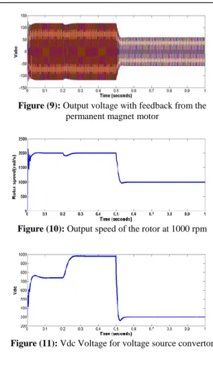
Figure (9): Output voltage with feedback from the permanent magnet motor
Figure (10): Output speed of the rotor at 1000 rpm
Figure (11): Vdc Voltage for voltage source convertor
Figure 12: Calculated EMF value (phase a)
Figure (13): Calculated three-phase EMF value
9. Conclusion
The permanent magnet synchronous motors have a lot of useful features in industrial applications. In the PMSM engine, the motor-cycle delay from the synchronous frequency results in instability of the motor and the motor must be restarted or synchronous frequency should be reduced to external control or locked onto the real cycle of the rotor. These motors are expensive due to their high speed performance and high efficiency, and in this case, high performance motors, all based on frequency-voltage, are used. In the
configuration of the system, a three-level converter of the voltage source is used to control and change the voltage and frequency. The output includes a designed constant voltage. In this way, the process of speed variation with a much higher dynamic response leads to a faster and better response than other control methods. The results indicate an increased speed of machine response in transient states and improve the accuracy of the response in the permanent state, as well as increased efficiency of permanent magnet synchronous motors by using sliding mode observer method.
FUNDING/SUPPORT
Not mentioned any Funding/Support by authors.
ACKNOWLEDGMENT
Not mentioned.
AUTHORS CONTRIBUTION
This work was carried out in collaboration among all authors.
CONFLICT OF INTEREST
The author (s) declared no potential conflicts of interests with respect to the authorship and/or publication of this paper.
References
1. Consoli,G. Scarcella,and A. Testa, “Industry Application of Zero-Speed Sensorless Control Techniques for PM Synchronous Motors”, IEEE Trans. Ind. App., vol. 37, No. 2, pp513519 March/April 2012. [Scholar]
2. S Bolognani, M Zigliotto, and M Zordan “Extended-Range PMSM Sensorless Speed Drive Based on Stochastic Filtering”, IEEE Trans. Power Elec, Vol. 16, No. 1, January 2006. [Scholar] 3. M. Leksell, L. Harnefors and M. Jansson, “Direct
Sensorless Speed Control of PM-Motors - a Simple and Effective Sensorless Method”, Published in the Proc. of Power Elec. Specialist Conference (PESC '01), Vancouver, Canada, June 2004. [Scholar] 4. Y. Bas, G. Tadmor and M. Stankovich, “Passivity
Based Sensorless Control of a Smooth Rotor Permanent Magnet Synchronous Motor”, Proc. Of 36th Conf. On Decision and Control, San Diego, California, USA, Dec. 1997. [Scholar]
5. K.S. Low, Y.Z. Deng, X.L. Guo, “Tow-degree-of-freedom Control of PMSM Drive without Mechanical Sensor”, IEEE trans, 2001, 38(6) pp.1650~1677. [Scholar]
6. S. Bolognani, R. Oboe and M. Zigliotto, “Sensorless Full-Digital PMSM Drive With EKF Estimation of Speed and Rotor Position”, IEEE Trans. Ind. Elec, vol. 46, No. 1, pp184191, February 1999. [Scholar] 7. T. Senjyu, T. Shimabukuro, K. Uezato, “Vector
Control of Permanent Magnet Synchronous Motors
without Position and Speed Sensors”, IEEE Trans. Ind. Elec, vol. 36, No. 1, pp150-161, December 2002. [Scholar]
8. Zhang Fengge, Liu Guangwei, Shen Yongshan and Wang Fengxiang, "Characteristic study of a novel PMSM with opposite-rotation Dual rotors.", in Proc. 2007 Proceeding of international Conference on Electrical Machines and System, pp.805~809. [Scholar]
9. Fengge Zhang, N.Neuberger, E.Nolle, P.Gruenberger, Fengxiang Wang."A new type of induction machine with inner and outer double rotors."Proceedings of IPEMC2004pp.286~289. [Scholar]
10. V. N. Ghate, and S. V. Dudul ," Optimal MLP neural network classifier for fault detection of three phase induction motor" Expert Systems with Applications, Vol. 37, No. 4, April 2010, PP. 3468– 3481. [Scholar]
11. P. V. J. R. guez and A. Arkkio," Detection of stator winding fault in induction motor using fuzzy logic" Applied Soft Computing, Vol. 8, No. 2, March 2008, PP. 1112–1120. [Scholar]
12. M. F.S.V. D’Angelo, R. M. Palhares, R. H.C. Takahashi, R. H. Loschi, L. M.R. Baccarini and W. M. Caminhas," Incipient fault detection in induction machine statorwinding using a fuzzy-Bayesian change point detection approach" Applied Soft Computing, Vol. 11, No. 1, January 2011, PP. 179-192. [Scholar]
13. Ronghai Qu, Lipo. T.A.,"Dual-rotor, radial-flux, toroidallywound permanent-magnet machines." Industry Applications, IEEE trans, 2003, 39(6) pp.1665~1673. [Scholar]
14. C. Navaneethakkannan and M. Sudha, "A simple method of tuning PID controllers for BLDC motor," in Intelligent Systems and Control (ISCO), 2013 7th International Conference on,2013, pp. 121-126. [Scholar]
15. Ying Fan, Li Zhang, Ming Cheng, and K. T. Chau, "Sensorless SVPWM-FADTC of a NewFlux-Modulated Permanent-Magnet Wheel MotorBased on a Wide-Speed Sliding Mode Observer," in 2015, IEEE TRANSACTIONS ON INDUSTRIAL ELECTRONICS, VOL. 62, NO. 5, pp.3143-3151. [Scholar]
16. Xiaoguang Zhang and Zhengxi Li, "Sliding-Mode Observer-Based Mechanical Parameter Estimation for Permanent Magnet Synchronous Motor," in2016. IEEE TRANSACTIONS ON POWER ELECTRONICS, VOL. 31, NO. 8, pp.5732-5745. [Scholar]
17. Yujie Zhao, Qingli Wang, Jinxue Xu and Chengyuan Wang, "A Fuzzy Sliding Mode Control Based on Model Reference Adaptive Control for Permanent Magnet Synchronous Linear Motor", 2nd IEEE Conference on Industrial Electronics and Applications, Page(s):980984, May 2007. [Scholar] 18. Junyou Yang, Ruijuan Chen and Naiguang Fa,
"A New Recurrent Fuzzy Neural Network Sliding Mode Position Controller Based on Vector Control of PMLSM Using SVM", IEEE International Power
Electronics and Motion Control Conference 2006. [Scholar]
19. Junyou Yang, Guofeng He and Jiefan Cui, "Analysis of PMLSM Direct Thrust Control System Based on Sliding Mode Variable Structure", IEEE International Power Electronics and Motion Control Conference, Volume 1, Issue 1, Page(s):1 – 5, Aug 2006. [Scholar]
20. Yang Junyou, He Guofeng and Cui Jiefan, "Sliding Mode Variable-structure Direct Thrust Control of PMLSM Using SVM", IEEE International Conference on Electrical Machines and Systems, Volume: 2, page(s): 1655-1658, 2005. [Scholar]
21. Fakoor, M., Kosari, A., & Jafarzadeh, M. (2016). Humanoid robot path planning with fuzzy Markov decision processes. Journal of applied research and technology, 14(5), 300-310. [Scholar] 22. Fakoor, M., Kosari, A., & Jafarzadeh, M.
(2015). Revision on fuzzy artificial potential field for humanoid robot path planning in unknown environment. International Journal of Advanced Mechatronic Systems, 6(4), 174-183. [Scholar] 23. Jafarzadeh, M., Gans, N., & Tadesse, Y.
(2018). Control of TCP muscles using Takagi– Sugeno–Kang fuzzy inference system. Mechatronics, 53, 124-139. [Scholar]