http://jpst.ripi.ir Journal of Petroleum Science and Technology 2017, 7(4), 91-101
ABSTRACT
Water injection strings in highly deviated wells are subjected to complex forces on the string bore. In this work, a mechanical model is developed for these forces and for those on downhole tools. On the basis of this model, and taking account of the characteristics of the string in different working conditions, a temperature field model and a pressure field model are introduced, and a statically indeterminate structural calculation method is adopted. A force tester for highly deviated wells is developed and used in eight tests on strings in the Jidong Nanpu oilfield making a comparison between the measurements from the tests and the results of calculations using the mechanical model indicates that the mechanical model exhibits high computational accuracy, with the errors at the wellhead being no more than 10%, and that the forces on packers calculated from the model are in accordance with those measured in the tests. Thus, the mechanical model developed in this work is suitable for analyzing the forces on water injection strings and downhole tools in highly deviated wells.
Keywords: Highly Deviated Well, Water Injection String, Packer, Mechanical Model, Mechanics Experiment Liu Jun1*, Wang Wei2, Liu Qingyou1, Xiao Guohua3, Zhang Jianzhong3, and Sang Guo2
1 School of Mechatronic Engineering, Southwest Petroleum University, Cheng Du Si Chuan 610500, China 2 School of Civil and Architecture Engineering, Southwest Petroleum University, Cheng Du Si Chuan 610500, China 3 Drilling Technology Research Institute of Jidong Oilfield Company, Tang Shan He Bei 063000, China
A Mechanical Model and its Experimental Verification for a Water
Injection String in a Highly Deviated Well
*Corresponding author Liu Jun
Email: [email protected] Tel: +86 134 388 57765 Fax: +86 134 388 57765
Article history
Received: January 09, 2016
Received in revised form: January 02, 2017 Accepted: January 15, 2017
Available online: November 15, 2017
INTRODUCTION
In many offshore oilfields, the restrictions imposed by surface and underground conditions are such that it is necessary to use directional and horizontal wells to enable exploitation. In addition, high-angle directional wells account for a high percentage of injection wells [1,2]. The use of both multiple pipe segments and high angles both increase the effect of friction on pipe columns, causing difficulties in their lowering and hoisting. Additionally, the higher intensity of pipe deformation and creep can
Journal of Petroleum Science and Technology 2017, 7(4), 91-101 http://jpst.ripi.ir production, with consequent economic losses [7,8].
Meanwhile, the water injection technique is being extended to zonal approaches and to deep wells [9–11], and the higher water injection pressures required lead to an increase in pressure differences between layers and to more diverse and complex working conditions; this results in further challenges to the reliability and safety of high-angle well water injection strings [12].
Although many theoretical and experimental studies have been carried out on various aspects of pipe string mechanics [13–20], there has been little research on high-angle water injection pipe columns, and no mature theoretical description of such systems is available. Three deficiencies in particular should be mentioned: (i) the existing mechanical models of high-angle water injection wells have not taken comprehensive account of the influence of temperature and pressure fields, frictional resistance, and downhole tools on the force and deformation of the pipe string; (ii) there have been no thorough examinations of the force characteristics of the pipe string; (iii) making a comparison between the measured data and theoretical results has rarely been carried out, owing to a lack of measurements of the force state of the pipe string, so the existing models have not been calibrated and validated satisfactorily, and their accuracy and practicability are limited. Therefore, this contribution aims to improve the theoretical mechanical model of water injection pipe strings in high-angle wells to, verify it using field test data, and to provide theoretical support for the design and construction of water injection pipe columns for high-angle wells.
EXPERIMENTAL PROCEDURES
Mechanical Model for Water Injection in
a Highly Deviated Well
Three Dimensional “Rigid Rope” Model
In this model, the effects of the water injection string stiffness and the curvature of the wellbore are taken fully into account in the force analysis of the curved portion. It is assumed that (i) the interaction between the well wall and the pipe string is a rigid continuous contact, (ii) the axis of the string coincides with the axis of the borehole, and (iii) the computational elements of the bent pipe in the sloping plane are iso-curvature segments of a circular arc. A three-dimensional “rigid rope” mechanical model is then established.A rectangular coordinate system is established as shown in Figure 1, and a natural system of coordinates on the string axis is also established. The equations describing the force on the curved portion of the string are then as follows:
Figure 1: an infinitesimal section force diagram.
( )
3
2 2
2 2
2
2 2 2
cos 0 2
2
2
sin 0
sin 0
t i i o o
m
t f
t
w
n t b m t
t n b m
n b
dT dP A dP A K EIdK N f q
ds ds
dM
RN R
ds v R D R
K d K
EI K T N N q
K ds
K dM
K N N q
ds K
N N N
α λ
α ϕ
µ α
τ µ
µ π ω
ω
µ α
µ α
− +
+ ⋅ ± + − =
= + +
+ −
− + ⋅ + + + =
− + − − =
= +
http://jpst.ripi.ir Journal of Petroleum Science and Technology 2017, 7(4), 91-101
where, α is the deviation angle of the borehole (rad), and ϕ is the azimuthal angle (rad); Kα is the rate of change of the deviation angle (rad/m), and Kϕ is
the rate of change of the azimuthal angle (rad/m);
1 /
f m s
K = −ρ ρ is the buoyancy factor (where ρm is the fluid density in the wellbore, and ρs is the density of the string), and q is the unit weight of the string in air (kN/m); qm is its unit weight in the fluid (kN/m);
n
N is the normal pressure on the string in the normal direction (kN), and Nb is the normal pressure on the string in the binormal direction (kN), µt is the friction coefficient in the circumferential direction; µα is the
friction coefficient in the axial direction, and Ai is the inner chamber cross-sectional area of the string (m2);
o
A is the inner chamber cross-sectional area of the casing (m2), and
o
P represents the pressure in the pipe (MPa); τf is the fluid force on unit length pipe due to the motion of the structure (N/m), and µ is the kinetic viscosity of the fluid (N·s/m2), ω stands for
the rotational speed of the string (rad/s), Dw is the wellbore diameter (m), R is the outside radius of the string (m), and v is the fluid velocity (m/s); E is the Young’s modulus of elasticity (kN/m3), and I is the
moment of inertia of the string (m4).
Under the effects of axial friction and interlayer pressure differences during the operation, once the load at the end of the string reaches a certain threshold, pipe string buckling instability will occur. This will generate additional positive contact pressure and thus additional friction. To provide a more accurate description, the three-dimensional “rigid rope” mechanical model is amended by including a critical load from sinusoidal or spiral buckling as follows:
4 5 7. 6 crs c crh c s EI T
R inusoidal bending
spiral bending r EI T Rr = = (2)
When there is the axial force, there is no buckling,
and there is sinusoidal buckling; moreover, when
z crh
T ≥T , there is spiral buckling. The corresponding
additional reaction forces are:
2 2 8 4 z s z h rT N EI rT N EI sinusoidal bending spiral bending = = (3)
When sinusoidal buckling occurs, the positive pressure on the string N becomes N N+ s ; when spiral buckling occurs, it becomes N N+ h.
Three-dimensional “Soft Rope” Mechanical
Model
In this model, the effects of water injection string stiffness and the curvature of the wellbore are not taken into account in the force analysis. Thus, in comparison with the “rigid rope” mechanical model, the following simplifying assumptions are made: (i) the effects of stiffness on the force of the string are neglected; (ii) the shear force on the string section is neglected. The resulting three-dimensional “soft rope” mechanical model is then given by:
( )
32 2
2
2 2 2
cos 0 2 2 2 sin 0 sin 0
t i i o o
m
t f
t
w
n t b m
t
t n b m
n b
dT dP A dP A N f q
ds
dM RN R
ds v R D R
k
K T N N q
k K dM
K N N q
ds k
N N N
α λ
α
ϕ
µ α
τ µ
µ π ω
ω µ α µ α − + ± + − = = + + + − ⋅ + + + = − + − − = = + (4)
These are nonlinear differential equations, which can be solved by a quasi-Newton method.
Temperature and Pressure Field Models
for a Water Injection String
Journal of Petroleum Science and Technology 2017, 7(4), 91-101 http://jpst.ripi.ir forces on the string will vary considerably, with the
string elongating or shortening because of changes in temperature and pressure, while its motion is simultaneously restricted, owing to the presence of packers and other downhole tools.
Temperature Field Model
The following assumptions are made in the numerical simulation models: (i) the stiffness of the string is such that it is in rigid and continuous contact with the borehole walls; (ii) the axis of the string coincides with the axis of the borehole, with the hole trajectory of the highly deviated well being described by the Frenet formula; (iii) the computational element of the pipe string is a circular arc on the sloping plane; (iv) before water injection, the pipe string, the fluid in the wellbore, and the ground are in thermal equilibrium. The initial temperature distribution is exhibited as the table geothermal gradient. After water injection, heat transfer in the radial and vertical directions of the wellbore due to mass transfer and thermal conduction is taken into account; (v) when discredited in the spatial domain, the material properties of each micro body domain such as the heat transfer coefficient and the specific heat are relatively stable; (vi) the water injection rate, water injection temperature, annual average subsurface temperature, and the geothermal gradient are constant; (vii) sufficiently far from the wellbore axis, r≥Rmax, the rock formation temperature is the original ground temperature. At the surface of the earth, Z=Zm, the temperature Tm does not change with time; below the surface, Z>Zm, the original rock formation temperature satisfies a linear relationship: Tdz=Tm+α z, where α is the rock formation temperature gradient; (viii) given the variety of conditions occurring in oil production operations, the influence of the last process on the next process must be considered in the
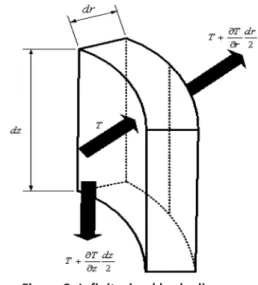
Figure 2: Infinitesimal body diagram.
On the basis of the above assumptions, in light of the first law of thermodynamics and the basic principles of heat transfer, considering the liquid in the pipe string, the string wall, and the liquid in the annulus, and with the stratigraphic unit taken as a control volume (see Figure 2), the mathematical model of the temperature field is given by the following energy balance equations:
(
)
(
) ( )
( )( )(
)
( )( )(
)
( )( )3
2
2 2 2 2 2
2
2 2 2 2 2
2 2 1 4 2 4 4 4 f f
f f ti f tf t f f f f f f
ti ti
t ti to t
t tf t f t a t t t
to ti to ti to ti
a to ci a
a t a t a c a a a
ci to to ti ci to ci to c
T T
c r v T T v c
z r r t
T r r T
k T T k T T c
t z r r r r r r
T r r T
k k T T k T T c
t z r r r r r r r r
T k
ρ α λ ρ ρ
α ρ ρ ∂ ∂ − + − + = ∂ ∂ ∂ − − + − = ∂ ∂ ∂ − − − ∂ ∂ − − + − = ∂ ∂ − − − − ∂
(
)
( )( )(
)
( )( )(
)
( )( )(
)
( )( )2 2 2 2 2
2
2 2 2 2 2
2 2 2 2
4 4
4 4
1
c ci co c
a c a c e c c c
co ci ci to co ci co ci
e co ce e
e c e c e w e e e
ce co co ci ce co ce co
w w w w w w
w
r r T
k T T k T T c
t z r r r r r r r r
T r r T
k k T T k T T c
t z r r r r r r r r
T T T c T r r k t z r ρ ρ ρ ∂ − − + − = ∂ − − − − ∂ ∂ ∂ − − + − = ∂ ∂ − − − − ∂ ∂ ∂ ∂ + + = ∂ ∂ ∂ ∂ )5(
where, Cf is the specific heat of the fluid in the pipe string (J/(kg·°C)), and αtf is the coefficient of convective heat transfer between the fluid in the string and the pipe wall (W/(m2·°C)); λ
f is the
http://jpst.ripi.ir Journal of Petroleum Science and Technology 2017, 7(4), 91-101
string (kg/m3); ν
f is the speed of fluid motion (m/s).
t
k , ka , kc , ke, and kw are respectively the heat conductivity coefficients of the injected fluid, the cylinder wall, the fluid within the annulus, the rock formation, and the original liquid mixing unit; ct , ca, cc, ce,and cw (J/(kg·°C)) are the respective specific heat capacities; andρt,ρa,ρc, ρe, and
w
ρ (kg/m3) are the respective densities.
to
r , rco,
ci
r , rti, and rce (m) are respectively the radius of the outer wall of the pipe string, the radius of the outer wall of the casing, the string inner radius, the radius of the inner wall of the casing, and the cement ring radius. The spatial domain is discredited using high-precision isoperimetric elements, and an optional implicit finite difference time domain with variable steps is used in a loop iteration, which allows the efficient and accurate calculation of the whole temperature field [21].
Pressure Field Model
The momentum equation for one-dimensional flow of the fluid under pressure is:
f a g
dP dP dP
dp
dz = dz + dz + dz (6) The variation in pressure due to changes in frictional resistance is given by:
f
dp
dz = −τ (7)
The variation due to changes in kinetic energy is given:
2 2
(1/ )
a m
dP U d
dz A dz
ρ
= (8)
Also, the variation due to changes in gravity and the hole deviation angle is given:
cos( )
g
dP g
dz = ρ θ (9)
Then, neglecting changes in fluid density, one way obtain:
cos( )
f g
dP dP
dP g
dz = dz + dz = − +τ ρ θ (10)
The pressure distribution along the well depth is found by integration, taking account of the boundary conditions:
0 0
( ) z[ ( ) cos( )]
P z =
∫
−τ z +gρ θ dz P+(11) When the coefficient of frictional resistance τ is constant, Equation 11 can be simplified:
0
( )= cos( )
P z − × +τ z gρ×z θ +P (12)
Mechanical Models for Pipe String and
Downhole Tools
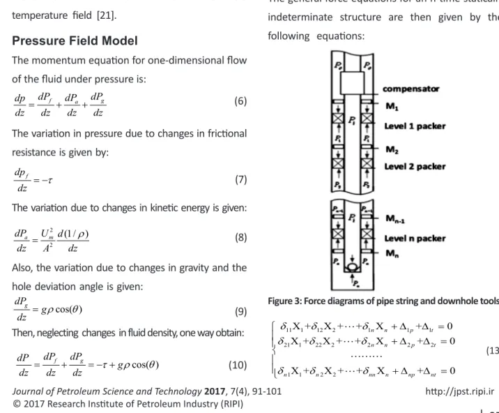
As shown in Figure 3, the packers are numbered from top to bottom, 1, ... n, the pipe anchoring tools as M1, M2, …, Mn+1, the corresponding forces on the packers as F1, F2,…, Fn, the annulus pressures
under the packers as P1, P2,…, Pn, and the lengths of the string between the packers as L1, L2,…, Ln. The general force equations for an n-time statically indeterminate structure are then given by the following equations:
Figure 3: Force diagrams of pipe string and downhole tools.
11 1 12 2 1 1 1
21 1 22 2 2 2 2
1 1 2 2
X + X + + X + 0
X + X + + X + 0
X + X + + X + 0
n n p t
n n p t
n n nn n np nt
δ δ δ
δ δ δ
δ δ δ
+ ∆ ∆ =
+ ∆ ∆ =
+ ∆ ∆ =
Journal of Petroleum Science and Technology 2017, 7(4), 91-101 http://jpst.ripi.ir where, ∆ip and ∆it are the displacements in the
i
X direction due to differential pressure and temperature; δij is the displacement in the Xi direction due to unit force Xj =1 , and Fi is the internal force at the level i packer caused by a dummy unit load; Fip and Fit are the internal forces due to differential pressure and temperature respectively.
The internal forces on the statically indeterminate structure are given by the superposition principle:
1 1 2 2 +
i n n ip it
F F X= +F X + F X +F +F (14)
Strength Calculations for a Water Injection
String in a Highly Deviated Well
To ensure the safety of the water injection string, its tensile, compressive, and collapsing strengths are first calculated. The force intensity is then obtained using the distortion energy theory. Finally, the synthesis safety factor is calculated.
The tensile-strength safety factor is given by the following equations:
rd rd
e
F K
q L
=
× (15)
e i i o o
q = +q ρ gA−ρ gA (16)
Brst-strength safety factor is given by the following equation:
( )
( ri )
rpi i o
i o
P
K p p
Max p p
= >
− (17)
The safety coefficient for resistance to external pressure is given by the following equation:
( )
( ro )
rpo o i
o i
P
K p p
Max p p
= >
−
(18) From the distortion energy theory, the tri-axial stress is given by the following equation:
( ) (2 ) (2 )2
1 2
xd r θ θ z z r
σ = σ −σ + σ −σ + σ −σ
(19)
Force Measurements for a High-angle
Pipe String
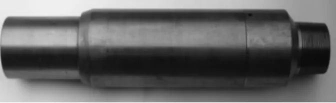
To verify the correctness of the model, a force tester, the composition of a resistance strain gauge transducer, a data acquisition circuit board, a power module, and a force test structure have been developed. The force test structure is composed of an inner barrel and an outer barrel, as shown in Figure 4. The data acquisition circuit board is contained within an electronic equipment enclosure, which is positioned eccentrically between the inner and outer barrels. The resistance strain gauge transducer is fixed to the inner ring groove. The complete force test substructure is shown in Figure 5. This force tester was used in site tests on a string in the Jidong Nanpu Oilfield, as described in the next section.
Figure 4: Mechanical structure of the test instrument. 1-screwed joint; 2,9-seal ring; 3,8-seal retainer; 4-outer barrel; 5-electronic equipment; 6-acquisition of circuit board; 7-inner barrel; 10-baffling barrel; 11-parallel external pipe thread; 12-slot.
Figure 5: Complete force test substructure.
The synthesis safety factor is also given by the following equation:
Min( rd, rpi, rpo, xd)
http://jpst.ripi.ir Journal of Petroleum Science and Technology 2017, 7(4), 91-101
Examples of Analysis and Experimental
Verification
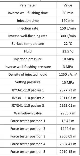
The mechanical model was used to analyze the forces on an unbalanced injection string in the third phase of the NP-XX well in the Jidong Nanpu Oilfield in different working conditions. The structure of the string and the positions where the experimental instruments were installed are shown in Figure 6; the azimuthal angle and hole drift angle parameters are shown in Figure 7, and the construction parameters of the well are listed in Table 1.
Table 1: Construction parameters of NP-XX
Parameter Value
Inverse well-flushing time 60 min Injection time 120 min
Injection rate 150 L/min Inverse well-flushing rate 300 L/min
Surface temperature 22 °C
Fluid 23.5 °C
Injection pressure 10 MPa Inverse well-flushing pressure 3 MPa
Density of injected liquid 1250 g/cm3 Setting pressure 15 MPa
JDY341-110 packer 1 2877.73 m JDY341-110 packer 2 2911.03 m JDY341-110 packer 3 2925.01 m Wash-down valve 2955.7 m Force tester position 1 15.45 m Force tester position 2 1244.6 m Force tester position 3 2866.09 m Force tester position 4 2867.47 m Force tester position 5 2910.15 m
Figure 6: String structure.
Dep
th (m)
Angle(°)
Figure 7: The azimuth angle and hole drift angle parameters.
Journal of Petroleum Science and Technology 2017, 7(4), 91-101 http://jpst.ripi.ir
Figure 8: Results in various conditions.
Lowering down tube Static
Setting 15Mpa (before Lifting) Setting 15Mpa (after Lifting)
Water injection Inverse well-flushing
Unsetting Lifting
Axial force (KN, pressure presents positive) Axial force (KN, pressure presents positive)
Axial force (KN, pressure presents positive)
Axial force (KN, pressure presents positive) Axial force (KN, pressure presents positive) Axial force (KN, pressure presents positive)
Axial force (KN, pressure presents positive)
http://jpst.ripi.ir Journal of Petroleum Science and Technology 2017, 7(4), 91-101
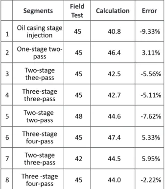
Owing to friction, the effect of pressure on the drill string force decreased with increasing well depth. The error in the calculated results compared with the measurements in the upper part of the tool section was small (<10%), while in the lower part of the tool section, owing to the small force and the limits on measuring conditions, the errors were larger. However, the calculated values of the drill string force were basically consistent with the values measured in the test.
Table 2: Comparison of measured and calculated forces for eight different loading conditions
Segments FieldTest Calculation Error
1 Oil casing stageinjection 45 40.8 -9.33%
2 One-stage two-pass 45 46.4 3.11%
3 Two-stagethee-pass 45 42.5 -5.56%
4 Three-stagethree-pass 45 42.7 -5.11%
5 Two-stagetwo-pass 48 44.6 -7.62%
6 Three-stage four-pass 45 47.4 5.33%
7 three-passTwo-stage 42 44.5 5.95%
8 Three -stagefour-pass 45 44.0 -2.22%
Table 2 compares the calculated results with the measured values of the drill string force when the strings were loaded together with the associated errors for eight different loading conditions. It is obvious that the errors in the calculated values of the lifting force on the string were within 10%, and the model is basically suitable for an engineering application.
Table 3: Force on packers
Packer
number Depth(m) (Downward Presents Positive)Force (kN)
1 2877.73 22.092
2 2911.03 -0.434
3 2925.01 -24.415
Table 3 shows the forces on the packers. In the condition of water injection, the packer at the first level was subjected to a downward force of 22.092 kN and the bottom packer to an upward force of 24.415 kN, which means that the pressures on the packers at both ends are greater than that on the intermediate packer. The pressure difference between the top and bottom packers generates a force that pushes the packers upwards and downwards. However, when the middle layer is injected with water, the upper and lower packers form a “self-balancing” system which will be pushed, so the upward and downward movement of the packer group will be prevented. Therefore, this corresponds well to practical engineering experiences.
CONCLUSIONS
(1) A mechanical model has been developed for analyzing the forces on an injection string with multiple packers in a highly deviated well with restrictions imposed by the presence of downhole tools. The model calculates the forces on the downhole tools and the string under various operating conditions, so the model provides a theoretical basis for the design and construction of injection strings.
Journal of Petroleum Science and Technology 2017, 7(4), 91-101 http://jpst.ripi.ir the design of the model. Making a comparison
between the model calculations and field test results indicates
that the computational accuracy of the model can satisfy practical engineering requirements.
(3) The results of the calculations provide a reasonable explanation for the “upward and downward push” phenomenon in which the force on the packers at both ends is greater than that on the intermediate packer. In practice, the ends of the packers should be anchored to prevent the motion of the packer group.
ACKNOWLEDGMENTS
This work has been supported in part by the National Science Foundation through Grant 2011ZX05050.
REFERENCES
1. Yafeng J., Jiuzheng Y., and Gengcheng Y., “The Research on Multilayer Fine Separated Layer Water Injection Technology in Jiyuan Oil Field,” Science Technology and Engineering, 2012, 18, 4504-4506.
2. Haiquan W., Xianming S., and Haitao Gen., “Concentric Layered Water Injection Technology Applied in Nanpu High Angle Wells,” China Petroleum Machinery, 2011, 9, 560-566.
3. Tao X. and Qingyou L., “Analysis of High Angle Well Water Injection Wellbore Pressure Calculation Model,” Petrochemical Industry
Application, 2015, 6, 12-15.
4. Hongwei Z., Jiang L., and Jijunet Y., “Mechanical Analysis on Tubular for Inverse Well Flushing in Deep Deviated Well,” China Petroleum Machinery, 2014, 10, 40-45.
5. Quanli J., “Mechanics Analysis of Layered
Water Injection Packer String,” Dissertation, Xian Petroleum University, 2014.
6. Baoxia Q., Ceji Q., and Congcong S., “Analysis and Design Research on Layered Water Injection String Mechanics,” China Petroleum and Chemical Industry, 2009, 1, 57-59. 7. Jingfu D., “Research on Remaining Oil
Description and Redeveloping Measures of PI-4 Oil Layer after Polymer Flooding in Nanwu Area,” Dissertation, Northeast Petroleum University, 2013.
8. Guohua Z., Jiangtao L., and Buhong J., “The Research and Application of New Type of Hollow Point’s Injection Process,” Fault Block Oil and Gas Field, 2007, 4, 80-82.
9. Junhui W., Lan H., and Jinqian Li., “Research of Oilfield Water Injection Mode,” 2014, 1, 84-88. 10. Yanping Z., “The Present Situation of the Oil
Field Injection Well Zonal Injection Technology and the Development Tendency,” China Petroleum and Chemical Standard and Quality, 2014, 6, 108.
11. Sheng S. and Jianfu L., “Oilfield Water Flood Technical Inquiry,” China Petroleum and Chemical Industry Standard and Quality, 2013, 20, 177.
12. Wei C., Xiaohong F., and Guangbing J., “Sea Controlled High Angle Well Liquid Separate Injection Technology,” China Petroleum Machinery, 2009, 11, 78-79.
13. Lubinski A., Althouse W. S., and Logan J. L., “Helical Buckling of Tubing Sealed in Packers,” Journal of Petroleum Technology, 1962, 14, 655-670.
14. Lubinski A., “Developments in Petroleum Engineering,” Houston, TX: Gulf Publishing, 1987.
http://jpst.ripi.ir Journal of Petroleum Science and Technology 2017, 7(4), 91-101
Technology, 1980, 32, 515-527.
16. Salies J. B., Azar J. J., and Sorem J. R., “Experimental and Mathematical Modeling of Helical Buckling of Tubules in Directional Wellbores,” in Proc. International Petroleum
Conference and Exhibition of Mexico, Veracruz,
Mexico, 1994, 433-443.
17. Payne M. L. and Abbassian F., “Advanced Torque and Drag Consideration in Extended-Reach Wells,” Society of Petroleum Engineering, SPE
Drilling Completion, 1997, 12(3), 55-62. 18. Hill T. H. and Chandler R. B., “Field Curves for
Critical Buckling Loads in Curving Well bores,” in Proc. IADC/SPE Drilling Conference, 3-6 March, Dallas, TX, 1998, 259-265.
19. Linqiang Z., “Calculating Model of Torque and Drag in Extended Reach Well,” Fault Block Oil and Gas Field, 2008, 2, 88-91.
20. Xiaohuaa Z., Yuan G., and Shaohu L., “Feasibility of Casing Entering Curved Part in Horizontal Well,” Oil Field Equipment, 2011, 4, 6-8. 21. Zuqing H., Xiaorong Z., and Guorong