Vol. 1, 2013, 71-75
ISSN: 2321 – 9238 (online) Published on 30 December 2013 www.researchmathsci.org
Progress in
Design and Implementation of Pollinators
(Electronic Bee’s) Using MEMS Technology
S.Selvam1 and V.Karthikeyan2
Department of EEE, Nehru Institute of Engineering and Technology Coimbatore – 641105, Tamilnadu, India
Email: 1[email protected]; [email protected]
Received 1 December 2013; accepted 12 December 2013
Abstract. The main aim of this proposed system is to safe guard the Nature, Nation’s security and mainly our valuable resources from getting diminished to our future generation. The eco stability is unbalanced by deforestation and many other cause, to maintain the growth rate in plant species and to safeguard the rare varieties (which is in the verge of extinct) of plants. The pollination by Birds and insects are reduced to a lot in the current scenario. MEMS (Micro Electro Mechanical System) are used to reduce the size and structure of the bees. It has a transmitter and receiver (Antenna), it detects the obstacle and to target the flower and destination which perform the operation by using commands. It would enhance the growth of many plant varieties. Cameras and Microphone are used for recording purpose. It can also be used as surveillance detector and in Defense to monitor the opponent. It will not affect the existing creature and surrounding environment.
1. Introduction
The pollination is the process carried out by birds and insect it was the major fact for the development in the green revolution. Due to radiations, number of birds and insect species are in the verge of extinct. Nothing can be fulfilled without food and nature. Without these criteria no one can survive. It’s highly typical to design and to find the problem in it is very complex, since there are numerous components in minute all are in micro level. It can be controlled and monitored by human. It does the work of insect which they would do in the process of pollination.
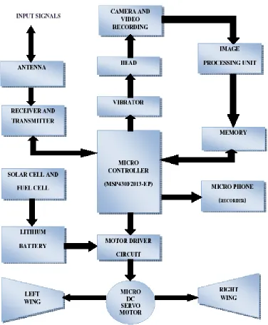
2. Block Diagram of Pollinators
This block diagram gives a clear view about the major process carried out by the bee, in various sections the posterior region consist of Camera’s and vibrators.
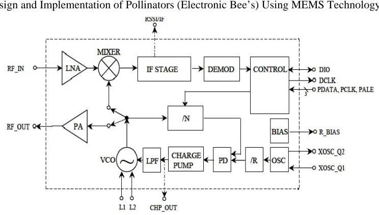
2.1. Radio Frequency Module (Transmitter and Receiver)
Figure 2: Block diagram of Transmitter and Receiver
A simplified block diagram of CC1000 is Only signal pins are shown above. In receive mode CC1000 is configured as a traditional super heterodyne receiver. The RF input signal is amplified by the low noise amplifier (LNA) and converted down to the intermediate frequency (IF) by the mixer (MIXER). In the intermediate frequency stage (IF STAGE) this down converted signal is amplified and filtered before being fed to the demodulator (DEMOD). As an option a RSSI signal, or the IF signal after the mixer is available at the RSSI/IF pin. After demodulation CC1000 outputs the digital demodulated data on the pin DIO. Synchronization is done on-chip providing data clock at DCLK. In transmit mode the voltage controlled oscillator (VCO) output signal is fed directly to the power amplifier (PA). The RF output is frequency shift keyed (FSK) by the digital bit stream fed to the pin DIO. The internal T/R switch circuitry makes the antenna interface and matching very easy. The frequency synthesizer generates the local oscillator signal which is fed to the mixer in receive mode and to the PA in transmit mode. The frequency synthesizer consists of a crystal oscillator (XOSC), phase detector (PD), charge pump (CHARGE PUMP), VCO, and frequency dividers (/R and /N). An external crystal Must be connected to XOSC, and only an external inductor is required for the VCO. The 3-wire digital serial interfaces (CONTROL) are used for configuration.
2.2.Wing Design and Working
Lilienthal and Clayey, in the 1800s, demonstrated that a curved surface produces more lift than a flat surface. This led to the conclusion that a wing needs to have camber. That is, the top needs to be slightly curved, like a hump. The bottom is left flat or straight. An object with this shape is called an airfoil. Often, the words "wing" and "airfoil" are used interchangeably, but they shouldn't be.
2.3. MEMS Microphones
The MEMS (Micro Electrical-Mechanical System) microphone is also called a microphone chip or silicon microphone. The pressure-sensitive diaphragm is etched directly into a silicon chip by MEMS techniques, and is usually accompanied with integrated preamplifier. Most MEMS microphones are variants of the condenser microphone design. Often MEMS microphones have built in analog-to-digital converter (ADC) circuits on the same CMOS chip making the chip a digital microphone and so more readily integrated with modern digital products. Major manufacturers producing MEMS silicon microphones are Wolfson Microelectronics (WM7xxx), Analog Devices, Akustica (AKU200x), Infineon (SMM310 product), Knowles Electronics, Memstech (MSMx), NXP Semiconductors, Sonion MEMS, AAC Acoustic Technologies, and Omron.
These microphones are used for recoding purpose [13], and it can be used in defense to gather the information regarding the opponent of the nation. Since its smaller in size it cannot be trapped easily
2.4. Vibrator
Industrial equipment is often used in scenarios where seeing or hearing a visual or audio alert can be hard. Micro vibration motors can be integrated into a design so that equipment operators and users can rely on a third sense - touch.
2.5. Memory
One of the most complicated areas of exploration undertakes will be the creation of a suite of artificial “smart” sensors, akin to a bee’s eyes and antennae. The ultimate aim is to design dynamic hardware and software that serves as the device’s ‘brain,’ controlling and monitoring flight, sensing objects such as fellow devices and other objects, and coordinating simple decision-making [16].
2.6. Battery
In generally much lighter than other types of rechargeable batteries of the same size. The electrodes of a lithium-ion battery are made of lightweight lithium and carbon. Lithium is also a highly reactive element, meaning that a lot of energy can be stored in its atomic bonds.
2.7. Solar Power
small devices, such a suitable device and power shall be in small sound systems. This keeps the e-bees in active state from power draining. This has been designed to be put apart with very little soldering, using mainly connector block and crimp terminals.
3. Conclusion and Future Approach
Thus is an excellent design though it has some drawbacks in the designing complexity. Various surveys can be conducted by this Electronic Bee’s. A Bee crew to be created in order to make various tasks such as data collecting, to detect the accidents and send signal to the respective department to make a remedy, to monitor in Institution organization, offices, traffic monitoring.
REFERENCES
1.
Website: https://robobees.seas.harvard.edu/2.
Secret Math of Fly Eyes Could Overhaul Robot Vision http:// www.wired.com/wiredscience/2009/11/fly-eyes/3.
http://www.thirdworldtraveler.com/Global_Secrets_Lies/Myth_FoodScarcity.html The Myth – Scarcity The Reality - There is enough food, Food First (Institute for Food and Development Policy) www.foodfirst.org4.
http://articles.timesofindia.indiatimes.com/2010-03-17/varanasi/28128843_1_food-grains-food-security-wheat-production5.
http://www.dailymail.co.uk/health/article-83999/Can-food-tablet.html6.
http://ieeexplore.ieee.org/xpl/RecentIssue.jsp?punumber=21; 264 – 273.7.
David F. Anderson, Understanding flight (MGH) 2001.8.
Theodore A. Talay, Introduction to Aerodynamics of Flight (NASA SP-367) 1975.9.
Gray Paul Nahban, Natural Bee Keeping: Organic approach to modern apiculture.10.
A national survey of managed honey bee 2011-12 winter colony losses in the UnitedStates: results from the Bee informed partnership, Available at:- http://www.ibra.org.uk/articles/US-honey-bee-winter-colony-losses-2011-12.