58
Comparing Semi Active Control of Bridge via
Variable Stiffness and Damping Systems and MR
Dampers
Fereydoon Amini 1*, Sara Zalaghi 1
1* Professor, College of Civil Engineering, Iran University of Science and Technology, Tehran, Iran ([email protected])
1 Research Assistant, College of Civil Engineering, Iran University of Science and Technology, Tehran, Iran
(Date of received: 11/12/2018, Date of accepted: 25/05/2019)
ABSTRACT
Semi active devices can be used to control the responses of a continuous bridge during earthquake excitation. They are capable of offering the adaptability of active devices and stability and reliability of passive devices. This study proposes two semi-active control method protection of bridge using variable stiffness and damping systems and MR dampers. The first method is variable stiffness and damping with eight different (on-off) control schemes which is optimized with genetic algorithm. Genetic algorithm is used to define the parameters of this method. In the second method, an intelligent controller using fuzzy control of MR damper is developed. In particular, a fuzzy logic controller is designed to determine the command voltage of MR dampers. In order to evaluate the effectiveness of the proposed method, the performances of the proposed controllers are compared in numerical study. Results reveal that the developed controllers can effectively control both displacement and acceleration responses of the continuous bridge.
Keywords:
59 1. Introduction
In recent decades, structural control methods have been developed to three main types of control system: passive, active and semi active system. Semi active control guarantees versatility and the adaptability of active control, and the reliability of the passive control system. Among various types of semi-active controls, one of the practical techniques for simultaneous reduction of total displacement and acceleration during earthquake excitation is seismic isolation [1]. Semi-active suspension is used with a controllable damper, such as fluid damper with variable orifices or magnetorheological (MR) damper [2]. At the same time, variable stiffness concepts have been widely studied for a variety of vibration control applications. Liu et all proposes a Voigot element to achieve variable spring stiffness by using variable damper along with springs connected in series [3]. Magneto-rheological (MR) damper, as semi-active control devices are fluid damper with variable orifices. They can provide large force capacity, high stability robustness and reliability [4]. A wide range of theoretical and experimental studies of a MR damper accepted due to recent rapid practical design related to the development of large scale MR dampers [5]. One of the challenges in the damping force exerted by an MR damper is mainly dependent an appropriate control algorithm to determined the command voltage of the MR damper. Many control algorithms have been proposed to determine input current of a MR damper. However, it isn't easy task because the MR devices are highly none linear to the input voltage [6].
60 2. Control System Design
In this section two semi-active control systems used to control the behavior of the bridge are described and the basic formulation of each method are explained.
2.1. Systems with Variable Characteristics
Systems with variable characteristics are developed to isolate or alleviate vibration because of the uncertainties of excitation such as earthquake in many literatures. The simple idea to develop a system with variable characteristics is to change the stiffness or damping coefficient of the system directly. This variable stiffness or damping systems are widely used in mechanic and civil engineering. The typical systems with variable stiffness or damping are semi-active or active suspension systems [10, 11]. In the paper, the main purpose of using variable stiffness and damping (VSVD) suspension system is to mitigate excitation on the continuous bridge.
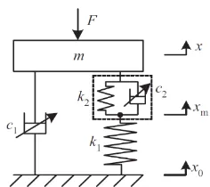
Figure 1. Mechanical configuration of variable stiffness and damping.
In order to illustrate the basic performance of variable stiffness and damping suspension system, a system with single degree of freedom is given in Fig 1. In the model, the suspension system consists of a set of two controllable dampers (corresponding damping coefficients of c1, c2 ) and two springs (corresponding damping stiffness of k1, k2 ) is proposed. Damper 2 and spring 2 comprise a Voiget element. The Voiget element and spring 1 are in series. The stiffness value of the two spring are constant. The aim of using damper 2 is to obtain a suspension system with variable stiffness performance. So the suspension system is a simple modification of a conventional suspension system. The governing equations of the suspension system can be depicted in eq. (1, 2):
𝑚𝑥̈ = −𝑘2(𝑥 − 𝑥𝑚) − 𝑐2(𝑥̇ − 𝑥̇𝑚) − 𝑐1(𝑥̇ − 𝑥̇0) − 𝐹 (1)
𝑘1(𝑥𝑚− 𝑥0) = 𝑘2(𝑥 − 𝑥𝑚) + 𝑐2(𝑥̇ − 𝑥̇𝑚) (2)
In Figure 1, F is an excitation force, 𝑥0, 𝑥 and 𝑥𝑚 are displacement of base , mass m and the point between the Voiget element and spring 1, respectively[4]. Eight types of control schems shown in Table 1. In Type 4 to Type 8 systems, on-off controlled in damper 1 and 2 as given respectively by eq.(3) and eq.(4). The on-off control algorithm of damper 1 uses the sign of the absolute velocity and the relative velocity. The force 𝑓𝑑1 generated by damper 1 is:
𝑓𝑑1= {−𝑐−𝑐1𝑜𝑛(𝑥̇ − 𝑥0̇ ) 𝑖𝑓 𝑥̇(𝑥̇ − 𝑥0̇ ) ≥ 0
1𝑜𝑓𝑓(𝑥̇ − 𝑥0̇ ) 𝑖𝑓 𝑥̇(𝑥̇ − 𝑥0̇ ) < 0
61
Where the damping coefficient 𝑐1 is equal to 𝑐1𝑜𝑛 in the on-state and 𝑐1𝑜𝑓𝑓 in the off-state. The control algorithm in damper 2 uses the sign of 𝑥̇(𝑥 − 𝑥0). The force 𝑓𝑑2 exerted by damper 2 is:
𝑓𝑑2= {−𝑐−𝑐2𝑜𝑛(𝑥̇ − 𝑥𝑚̇ ) 𝑖𝑓 𝑥̇(𝑥 − 𝑥0) ≥ 0
1𝑜𝑓𝑓(𝑥̇ − 𝑥𝑚̇ ) 𝑖𝑓 𝑥̇(𝑥 − 𝑥0) < 0
(4)
The values were used in the numerical calculation: 𝑐1𝑜𝑓𝑓 =120𝜋 𝑁𝑆/𝑐𝑚, 𝑐1𝑜𝑛 =600 𝜋 𝑁𝑆/𝑐𝑚
, 𝑐2𝑜𝑓𝑓 =69 𝜋 𝑁𝑆/𝑐𝑚 , 𝑐2𝑜𝑛 = 6930𝜋 𝑁𝑆/𝑐𝑚, 𝑘1 = 1200𝜋2and 𝑘2 = 𝑘1/3 . Figure 3(a) shows the schematic diagram of the VSVD control system implementation.
Table 1. Control systems.
Damper2 Damper1 Name off off Soft system Type1 on off Low damping Type2 on on High damping Type3 off On-off D on-off(soft) Type4 on On-off D on-off(stiff) Type5 on-off off S on-off(low) Type6 on-off on S on-off(high) Type7 on-off On-off D+S on-off Type8
2.2. MR Damper System
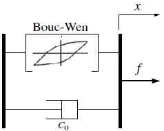
A number of mechanical models for nonlinear damper have recently been proposed by several researchers [4, 5]. In this study, the Bouc-Wen model is used to model the dynamic behavior of the MR damper. A simple mechanical model for the MR damper consisting of a Bouc-Wen element in parallel with a viscous damper is used, as shown in Figure 2.
Figure 2. Bouc-Wen model for dynamic behavior of MR damper.
Table 2. Parameters for the MR damper model.
Value Parameter Value Parameter Value Parameter
3(𝑐𝑚−1) 𝛽
44.0 (𝑁 𝑐𝑚⁄ ⁄ )𝑉 𝑐0𝑏
1.0872× 10⁵(N∕ 𝑐𝑚)
𝛼𝑎
3(𝑐𝑚−1) 𝛾
1.2 𝐴𝑚
4.9616× 10⁵(𝑁 𝑐𝑚⁄ ⁄ )𝑉 𝛼𝑏
3(𝑠−1) 𝜂
1 N
62
The equation governing the force 𝑓 exerted by this model are as follows:
𝑓 = 𝑐0𝑥̇ + 𝛼𝑧 (5)
𝑧̇ = −𝛾|𝑥̇|𝑧|𝑧̇|𝑛−1− 𝛽𝑥̇|𝑧|𝑛+ 𝐴
𝑚𝑥̇ (6)
Where 𝑥 =the displacement of the device, and 𝑧 =the evolutionary variable the accounts for the history dependence of the response. The Parameters 𝛾. 𝛽. 𝑛. and 𝐴𝑚 are adjusted to determine the linearity in the unloading and smoothness of the transition from the pre-yield region to the post-yield region. Device model parameters 𝛼 and 𝑐0 are determined by the dependency on the control
voltage u, as follows:
𝛼 = 𝛼(𝑢) = 𝛼𝑎+ 𝛼𝑏𝑢 (7)
𝑐0= 𝑐0(𝑢) = 𝑐0𝑎+ 𝑐0𝑏𝑢 (8)
Therefore, the control voltage applied to the current driver in an MR damper continuously modulate the damping force of the MR damper. Moreover, to account for a time-lag in the response of the device to the changes in the command input, the first-order filter dynamics are introduced in to the system as follows:
𝑢̇ = −𝜂(𝑢 − 𝑣) (9)
3. Developments of Control Algorithms 3.1. Genetic Optimal Control Algorithm
As described previously, the design purpose of variable stiffness and damping control with eight schemes the reduction of dynamic responses such as total displacement. An appropriate approach to find the optimum parameters of a VSVD control is to employ computation search techniques. Genetic algorithm (GA) is one of such search techniques based on mechanics of natural genetics. GA searches large spaces without the need of derivative information. Here, single-objective genetic algorithm (SOGA) is used to generate the parameter of VSVD control that specify the force of dampers installed on the bridge. With its powerfull nature, SOGA can efficiently search for effective parameters, additionally it is possible to design a controller that has capability of optimizing displacement response of the bridge using genetic optimization algorithm [8].
63
After selection, crossover and mutation, a new population is generated in both GA coding. This new population repeats the same process iteratively until a defined condition.
3.2. Semi- Active Fuzzy Control Strategy
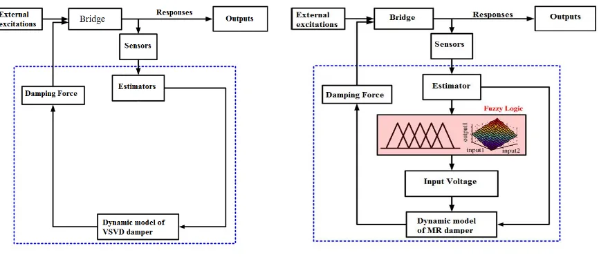
This section explains the semi-active fuzzy control strategy for modulating the MR damper. As shown in the previous section, the magnitudes of the model parameters α and c_0 varies with the input voltage of the MR damper, which lead to the modulation of the damping force of the MR damper. In Fig 3(b) shows a conceptual diagram of a fuzzy control strategy. The semi-active control fuzzy logic strategy takes the response of the MR damper as input information and the input voltage to MR damper as output information. This fuzzy logic is typically consisted of 4 steps: fuzzification, rule-base, inference mechanism, and defuzzification [13].
a)Semi-active variable stiffness and variable damping control b)semi-active Fuzzy control
Figure 3. Conceptual diagrams of semi-active control strategies.
64 4. Numerical Studies and Discussion
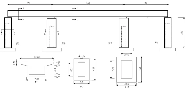
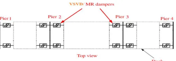
A type of three-span continues concrete bridge as a target used in this study. This continues box Girder Bridge having a total length of 340m with the main span of 160m and two end spans of 90m and the cross sectional details are shown in Fig 4. This continues bridge was modeled using 30 MPa ultimate strength concreate and 190 MN weight of the girder. The maximum allowable displacement is 0.3m this continuous bridge model without controller is used as a model for evaluating the control system. By placing damper devices between the girder and the pier as shown in Fig 5, the damper force generated due to the piston movement will be adjusted independently for each damper based on the control algorithm which is discussed below.
Figure 4. Target bridge model (unit:m).
The numerical simulation of the seismic responses of the benchmark continues bridge are performed within the MATLAB environment through a SIMULINK block. The governing equation of motion for continuous bridge under seismic excitation is:
𝑴𝑥̈(𝑡) + 𝑪𝑥̇(𝑡) + 𝑲𝑥(𝑡) = −𝑴 ∙ Γ ∙ 𝑢̈𝑔(𝑡) + Λ𝑭𝑢(𝑡) (10)
Where M, C and K are mass, damping and stiffness matrices of the bridge, Γ and Λ are the location matrices for ground acceleration 𝑢̈𝑔(𝑡)and control force of the damper𝑭𝑢(𝑡) , the
vectors 𝑥̈(𝑡), 𝑥̇(𝑡) and 𝑥(𝑡) are the acceleration, velocity and displacement, respectively. Considering Z(t)=[𝑥(𝑡) 𝑥̇(𝑡)]𝑇, Eq (10) in state-space form gives:
𝑍̇(𝑡) = 𝐴𝑍(𝑡) + 𝐵𝑢(𝑡) + 𝐻𝑢𝑔̈ (𝑡) (11)
Where the state matrix, A, and input matrix B and H are as follows:
In Eq. (12), I and 0 are identify and Zero matrices respectively.
( 12 )
A=[ 0 I
65
Figure 5. Installation layout of VSVD/MR dampers.
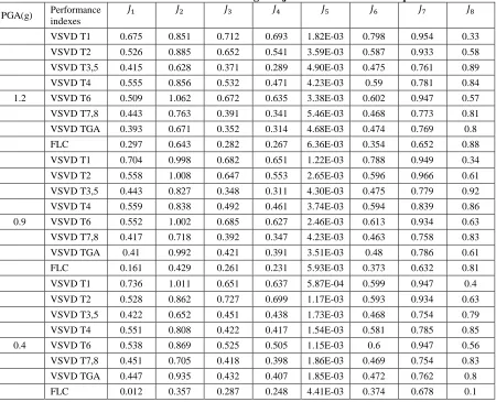
To examine the effectiveness of the bridge by the proposed control algorithms, El Centro ground motion are used as input excitation. The peak ground acceleration is scaled to 0.4g, 0.9g, 1.2g which are corresponding to the medium, strong and extreme level earthquake. Dynamic response analysis is conducted in the longitunal direction of the bridge. In addition, this bridge is assumed to be attached to bed rock, and the effect of soil-structure interaction are neglected. There are eight sets of evaluation criteria which are used in the benchmark problem in structural control to evaluate the performance of the bridge, 𝐽1to 𝐽8, as shown in Table 3.
Table 3. Performance indices.
Peak base over turning moment Peak base shear
Peak acceleration Peak displacement
𝐽4=𝑚𝑎𝑥|𝑀𝑚𝑎𝑥|𝑀̂𝑏(𝑡)|
𝑏(𝑡)|
𝐽3=𝑚𝑎𝑥|𝑉𝑚𝑎𝑥|𝑉̂𝑏(𝑡)|
𝑏(𝑡)|
𝐽2=𝑚𝑎𝑥|𝑎𝑚𝑎𝑥|𝑎̂𝑑(𝑡)|
𝑑(𝑡)|
𝐽1=𝑚𝑎𝑥|𝑥(𝑡)|𝑚𝑎𝑥|𝑥̂(𝑡)|
Energy dissipated by device RMS displacement
RMS displacement Peak controlled force
𝐽8=
{∫ [𝑥̇(𝑡)𝐹(𝑡)]𝑇 2𝑑𝑡
0 }
1/2
{∫ [𝑥0𝑇 𝑔̇ (𝑡)𝑉𝑏(𝑡)]2𝑑𝑡} 1/2
𝐽7=𝑚𝑎𝑥|𝜎𝑎𝑚𝑎𝑥|𝜎̂𝑎𝑑(𝑡)|
𝑑(𝑡)|
𝐽6=𝑚𝑎𝑥|𝜎𝑥(𝑡)|𝑚𝑎𝑥|𝜎̂𝑥(𝑡)|
𝐽5=𝑚𝑎𝑥|𝐹(𝑡)|𝑊
66
In three scaled levels of El Centro earthquake, it can be seen that proposed controller significantly reduce 𝐽1 and 𝐽6 , which are performance indices related to the maximum displacement and the value of its RMS, respectively. For example, in comparison with the uncontrolled structures under the El Centro ground motion with PGA of 1.2g the seismic reduction displacement ratio of the bridge are 70.3%, 60.7%, 58.5% and 55.7%, for FLC, VSVD TGA, VSVD T3,5 and VSVD T6,7 respectively. It is clear that the FLC is more effective in reducing the displacement of the bridge than other proposed controller.
Table 4. Performance indices of the bridge subjected to El Centro earthquake.
PGA(g) Performance
indexes
𝐽1 𝐽2 𝐽3 𝐽4 𝐽5 𝐽6 𝐽7 𝐽8
VSVD T1 0.675 0.851 0.712 0.693 1.82E-03 0.798 0.954 0.33
VSVD T2 0.526 0.885 0.652 0.541 3.59E-03 0.587 0.933 0.58
VSVD T3,5 0.415 0.628 0.371 0.289 4.90E-03 0.475 0.761 0.89
VSVD T4 0.555 0.856 0.532 0.471 4.23E-03 0.59 0.781 0.84
1.2 VSVD T6 0.509 1.062 0.672 0.635 3.38E-03 0.602 0.947 0.57
VSVD T7,8 0.443 0.763 0.391 0.341 5.46E-03 0.468 0.773 0.81
VSVD TGA 0.393 0.671 0.352 0.314 4.68E-03 0.474 0.769 0.8
FLC 0.297 0.643 0.282 0.267 6.36E-03 0.354 0.652 0.88
VSVD T1 0.704 0.998 0.682 0.651 1.22E-03 0.788 0.949 0.34
VSVD T2 0.558 1.008 0.647 0.553 2.65E-03 0.596 0.966 0.61
VSVD T3,5 0.443 0.827 0.348 0.311 4.30E-03 0.475 0.779 0.92
VSVD T4 0.559 0.838 0.492 0.461 3.74E-03 0.594 0.839 0.86
0.9 VSVD T6 0.552 1.002 0.685 0.627 2.46E-03 0.613 0.934 0.63
VSVD T7,8 0.417 0.718 0.392 0.347 4.23E-03 0.463 0.758 0.83
VSVD TGA 0.41 0.992 0.421 0.391 3.51E-03 0.48 0.786 0.61
FLC 0.161 0.429 0.261 0.231 5.93E-03 0.373 0.632 0.81
VSVD T1 0.736 1.011 0.651 0.637 5.87E-04 0.599 0.947 0.4
VSVD T2 0.528 0.862 0.727 0.699 1.17E-03 0.593 0.934 0.63
VSVD T3,5 0.422 0.652 0.451 0.438 1.73E-03 0.468 0.754 0.79
VSVD T4 0.551 0.808 0.422 0.417 1.54E-03 0.581 0.785 0.85
0.4 VSVD T6 0.538 0.869 0.525 0.505 1.15E-03 0.6 0.947 0.56
VSVD T7,8 0.451 0.705 0.418 0.398 1.86E-03 0.469 0.754 0.83
VSVD TGA 0.447 0.935 0.432 0.407 1.85E-03 0.472 0.762 0.8
FLC 0.012 0.357 0.287 0.248 4.41E-03 0.374 0.678 0.1
Also considering indices 𝐽2 and 𝐽7 , it can be seen that decreases in maximum acceleration in
67
0.8%, 0.2% for VSVD T2 and VSVD T6 respectively with a PGA of 0.9g and 1.1% for VSVD T1 with a PGA of 0.4g. Considering 𝐽1and𝐽6 whichare performance indices related to the maximum displacement and it can be the value of its RMS.
68
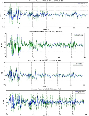
Figure 7. Control Force time histories of the side pier under El Centro earthquake with a PGA 1.2 g.
69
the proposed system still shows very competent control performance. Nonetheless, using 𝐽5 evaluation criteria all of the proposed controller methods described above are the same range based on the maximum control force.
The value of indice 𝐽8 indicate that the performance of the proposed controller can be compared in terms of dissipated energy normalized by input excitation energy. The VSVD T3.5 controller perform better than other control strategies in term of dissipation of input excitation energy in three scaled levels of El Centro earthquake. It should be noted the FLC, VSVD T3.5 and VSVD TGA controllers by comparison in term of dissipated energy and maximum control force are almost the same range, while FLC controller provides a better performance in reduction in maximum displacement and maximum acceleration.
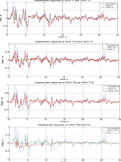
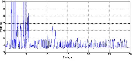
Considering three scaled level of El Centro earthquake which are corresponding to the medium, strong and extreme level earthquake. Fig 6 shows the displacement time histories of proposed controllers in side piers under the extreme level with a PGA of 1.2 g. It is evident that control efficiencies of both VSVD TGA and FLC on the piers of continues bridge are generally higher than the other proposed controller. Fig 7 shows the time histories of controlled force generated in side pier of proposed controllers under the extreme level with a PGA of 1.2 g. It is indicated the same range of control force entered to continues bridge. The time history of the command voltage provided by the FLC control is presented in Figure 8. It can be seen that the maximum command voltage is '10 V' during real-time control.
Figure 8. Time history of command voltage.
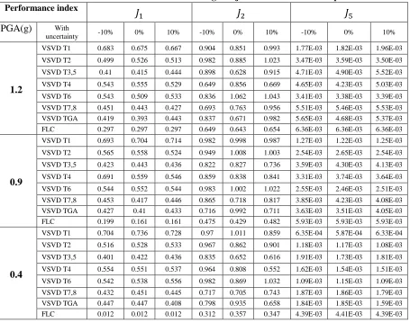
Finally, in order to assess the stability of sensitivity of the proposed controllers with regard to uncertainties in seismic excitation, simulations of the bridge under three scaled level of El Centro earthquake. To investigate the sensitivity of the proposed controller uncertainties, an uncertainty of ±10% in the stiffness is considered. For three important performance indices i.e. 𝐽1, 𝐽2 and 𝐽5 ,
70
Table 5. Performance indices of the bridge subjected to El Centro earthquake. Performance index 𝐽
1 𝐽2 𝐽5
PGA(g) With
uncertainty -10% 0% 10% -10% 0% 10% -10% 0% 10%
1.2
VSVD T1 0.683 0.675 0.667 0.904 0.851 0.993 1.77E-03 1.82E-03 1.96E-03
VSVD T2 0.499 0.526 0.513 0.982 0.885 1.023 3.47E-03 3.59E-03 3.50E-03
VSVD T3,5 0.41 0.415 0.444 0.898 0.628 0.915 4.71E-03 4.90E-03 5.52E-03
VSVD T4 0.543 0.555 0.529 0.649 0.856 0.669 4.65E-03 4.23E-03 5.03E-03
VSVD T6 0.543 0.509 0.533 0.836 1.062 1.043 3.41E-03 3.38E-03 3.39E-03
VSVD T7,8 0.451 0.443 0.427 0.693 0.763 0.956 5.51E-03 5.46E-03 5.53E-03 VSVD TGA 0.419 0.393 0.443 0.837 0.671 0.982 5.65E-03 4.68E-03 5.37E-03 FLC 0.297 0.297 0.297 0.649 0.643 0.654 6.36E-03 6.36E-03 6.36E-03
0.9
VSVD T1 0.693 0.704 0.714 0.982 0.998 0.987 1.27E-03 1.22E-03 1.25E-03
VSVD T2 0.565 0.558 0.524 0.949 1.008 1.003 2.54E-03 2.65E-03 2.54E-03
VSVD T3,5 0.423 0.443 0.436 0.822 0.827 0.736 3.59E-03 4.30E-03 4.13E-03
VSVD T4 0.691 0.559 0.546 0.859 0.838 0.841 3.31E-03 3.74E-03 3.64E-03
VSVD T6 0.544 0.552 0.544 0.983 1.002 1.022 2.55E-03 2.46E-03 2.51E-03
VSVD T7,8 0.453 0.417 0.446 0.865 0.718 0.817 3.85E-03 4.23E-03 4.08E-03 VSVD TGA 0.427 0.41 0.433 0.716 0.992 0.711 3.63E-03 3.51E-03 4.05E-03 FLC 0.199 0.161 0.161 0.475 0.429 0.482 5.93E-03 5.93E-03 5.93E-03
0.4
VSVD T1 0.704 0.736 0.728 0.97 1.011 0.859 6.35E-04 5.87E-04 6.33E-04
VSVD T2 0.516 0.528 0.533 0.967 0.862 0.901 1.18E-03 1.17E-03 1.08E-03
VSVD T3,5 0.401 0.422 0.436 0.835 0.652 0.616 1.91E-03 1.73E-03 1.81E-03
VSVD T4 0.554 0.551 0.537 0.964 0.808 0.552 1.62E-03 1.54E-03 1.51E-03
VSVD T6 0.542 0.538 0.556 0.982 0.869 1.032 1.09E-03 1.15E-03 1.09E-03
VSVD T7,8 0.432 0.451 0.445 0.717 0.705 0.743 1.87E-03 1.86E-03 1.79E-03 VSVD TGA 0.447 0.447 0.408 0.798 0.935 0.658 1.84E-03 1.85E-03 1.59E-03 FLC 0.012 0.012 0.012 0.312 0.357 0.347 4.39E-03 4.41E-03 4.39E-03
5. Conclusions and Discussions
71
The simulation results demonstrate that the fuzzy controlled MR damper system is quiet effective in reducing the responses of continues bridge to a medium, strong and extreme level earthquake.
6. References
[1]-Housner, G. W., Bergman, L. A., Caughey, T. K., Chassiakos, A. G., Claus, R. O. and Masri, S. F., 1997, Structural control: past, present, and future, Journal of Engineering Mechanics,123(9), 897-971.
[2]- Oh, S. K., Yoon, Y. H., Krishna, A. B., 2007, A study on the performance characteristics
of variable valve for reverse continuous damper, World Academic Science, Engineering
Technology, 32, 123–128.
[3]- liu, Y., Matsuhisa, H., Utsuno, H., 2008, Semi-active vibration isolation system with
variable stiffness and damping control, Journal of sound and vibration, 313, 16-28.
[4]- Dyke, S. J., Spencer, B. F., Sain, M. K., Carlson, J. D., 1996, Modelling and control of
magnetorheogical dampers for seismic response reduction, Smart Material Structure, 5,
565-575.
[5]- Sodeyama, H., Sunakoda, K., Suzuki, K., Carlson, J. D., Spencer, Jr. B. F., 2001, Development
of large capacity semi active vibration control device using magnetorheological fluid, Seismic
Engineering ASME PVP, 428(2), 109-114.
[6]-Yi, F., Dyke, S. J., Caicedo, J. M., Carlson, J. D., 2001, experimental verification of
multinput seismic control strategies for smart dampers, Journal of Engineering Mechanics,
127(11), 1152-1164.
[7]- liu, Y., Matsuhisa, H., Utsuno, H. and Park, J. G., 2005, Vibration isolation by a variable
Stiffness and Damping System, International Journal Society of Mechanical Engineering, 48(2),
305-310.
[8]- Marano, G. C., Quaranta, G., and Monti, G., 2011, Modified genetic algorithm for the
dynamic identification of structural systems using incomplete measurements, Computing-
Aided Civil Infrastructure Engineering, 26(2), 92-110.
[9]- Lee, C. C., 1995, Fuzzy logic in control system: fuzzy logic controller part I and part II., IEEE Transaction System Man, and Cybernetics, 20, 404-418.
[10]- Cronje, J. M, Stephan, P., and Theron, N. J., 2005, Development of a variable stiffness and
damping runnable vibration isolator, Journal Vibrate control, 11(3), 381-396.
[11]- Gonca, V., and Shavab, J., 2010, Design of elastomeric shock absorbers with variable
stiffness, Journal Vibroengineering, 12(3), 347-354.
[12]- Yoshida, O., and Dyke, S. J., Seismic control of a nonlinear benchmark building using
smart dampers, Journal of Engineering Mechanics, 130(4), 386-392.
[13]- Park, K. S., Koh, M. H., and Seo, C. W., 2004, Independent model space fuzzy control of