1
Numerical Methods in Civil Engineering
Seismic behavior of drilled beam section in moment connections
S. Kazerani* , N. Fanaie**, S. Soroushnia***
ARTICLE INFO
Article history: Received: September 2016. Revised: March 2017. Accepted: April 2017.
Keywords: Reduced Beam Section, Drilled Beam Section, Cyclic Loading, Hysteretic, Energy Dissipation
Abstract:
Reduced Beam Section (RBS) and Drilled Beam Section (DBS) are seismic moment resistant frame connections, introduced after 1994 Northridge earthquake. RBS connection has been tested under cyclic loading and showed acceptable performance. In this paper, seismic behavior of Drilled Beam Section (DBS) connection is studied numerically using finite element method. A drilled beam section of a cantilever H-beam has been subjected to cyclic loading at its free end and studied for its optimal shapes. 62 samples of DBS connections have been modeled and studied under cyclic and pushover loadings. Based on the results obtained in this research, the connection shows its positive seismic behavior if the biggest hole is near the column face and its diameter decreases as the holes move away from the column face. In this research the effects of dimensions, position and number of holes are investigated using Von Mises stress and elastic strain criteria under cyclic and monotonic loadings. In this drilled beam the smaller holes shift plastic hinges out of the connection zone.
.
1.
Introduction
Buildings are damaged under seismic loading mostly due to destruction of beam-column connections which can lead to the loss of their strengths and result in the collapse of the floors. Special steel momentresistant frames were typically used in the seismic areas of United States until the earthquake of Northridge, January 1994. Many steel buildings with moment frames were seriously damaged in this earthquake. The scientific communities realized that extra researches should be conducted to understand the behavior of these connections under cyclic loading. As a result, researchers have suggested two solutions to improve the ductility of moment connections: 1) Increasing the strength of the connections by stiffeners and appropriate welds in order to prevent the connections from damage;
2) Weakening a beam section away from the column face, at which a plastic hinge is inevitably formed without damaging the column [1, 2].
* Corresponding Author: Graduate Student, Department of Construction,
Science and Research branch, Islamic Azad University, Kermanshah, Iran; Email: [email protected]
** Assistant Professor, Civil Engineering Department, K.N.Toosi University of Technology, Tehran, Iran.Email:[email protected]
*** Graduate Student, Department of Civil Engineering, Islamic Azad University, Takestan Branch, Takestan,Iran; E-mail: [email protected]
The connections developed since 1994 Northridge earthquake, have been frequently reinforced with cover plates, ribs and side plates. Reduced Beam Sections (RBS) or “Dogbone” connections are considered as promising alternatives to reinforce connections in the steel moment frames. Luxembourg-based steel manufacturing company (ARBED) obtained a patent on the RBS in 1989. This patent was released in 1995 for the benefit of the structural design community [3].
This gracious gesture allowed further development of the concept for being used in the post-Northridge special moment resistant frames. Dogbone type connections have been proposed and tested by several researchers [3].
With respect to plastic theory, when a section of member has become entirely plastic due to a bending moment, any attempt to increase the moment will result in the section acting as a plastic hinge.. In the presence of a plastic hinge, large rotations may occur without any significant change in the moment resisting frame. Such rotations indicate high ductility of the member. In strong ground motions, plastic hinges tend to be formed at the beam ends in a steel moment resistant frame. When the connection is reinforced, plastic hinges are formed away from the column face. In such cases the stress in the connection is reduced. By trimming the flanges of the beams, the stresses are induced at the weaker
Numerical Methods in Civil Engineering, Vol. 1, No.4, June.2017
zones. Consequently, when the stresses are moved away from the beam-column connection, large rotations occur at the plastic hinges. The reduced sections allow the connection strength to exceed the beam strength without the need for reinforcement of connections. By moving the stresses away from the beam-column connection, yielding occurs in the reduced section and the potential for brittle failure is reduced at the connection [3]. RBS connections have been proposed and tested by several investigators. Rea, Clough, and Bouwkamp [4] employed a constant cut dogbone at a column base connection. Plumier [5] studied both constant and variable cut dogbones. Chen and Yeh [1] conducted five tests on variable cut dogbone.
All these researches were carried out before the 1994 Northridge earthquake. These studies confirmed the improvement of seismic performance in the presence of dogbone cutouts in the beams. Following the Northridge earthquake, dogebone connections have been studied with renewed interests. Iwankiw and Carter [6] tested four large scale specimens constructed with variable cut RBSs. Although high ductility was developed in these specimens, two out of four specimens ultimately fractured at their beam-column connections. Zekioglu et al. [7] examined five large scale specimens with variable cut RBSs. Besides using RBS cutouts in the beams, they reinforced the connections with ribs. These specimens had also developed high ductility, but finally failed because of the beam fracture within the dogbone region. The fractures were developed at the minimum section of variable cutouts, apparently due to the concentration of stress at the location of reduced beam. Engelhardt et al. [8, 9] demonstrated that the radius cut minimizes the concentration of stress in the RBS region by presenting its excellent performance in the laboratory. The Drilled Beam Section (DBS) connection which is a type of RBS connection has been analyzed using ABAQUS finite element (FE) software [10].
2. Analytical Studying of DBS Moment Connections
In this research, M. Ohsaki et al. model [11]has been used to investigate DBS connections and plot its relevant hysteresis curves. In addition, the performance of connection has been studied under cyclic loading and pushover analysis. Dimension, position and center to center distance of drilled holes in the beam flanges are considered in DBS connection to find out the best option regarding the seismic performance. Accordingly, 62 samples of such connections have been modeled in order to achieve better covering content. The dimensions of the holes used in the samples are 10, 12.5, 15, 17.5 and 20 mm. The symbols used for expressing the characteristics of connections are: N for same diameter of the
hole; S for special cut out; D and A for descending and ascending diameters of the hole along beam flanges, respectively; P for Particular; and O for Opposite. In DBS-D, the largest hole is located near the column face and the size of holes is reduced by moving away from the column. In DBS-A, the smallest hole is located near the column face and the sizes of holes is increased by moving away from the column.
Fig. 1 shows the connections of DBS with three drilled holes. The models have been studied for different types of drilled beam sections with single, double and triple holes.
Fig. 1: Typical DBS connections
2.1. Finite Element Analysis
ABAQUS finite element software is applied to model the specimens for nonlinear analysis. It is focused on overall cyclic behavior of DBS connections in addition to the effects of dimensions, position and number of holes, and presented in the following figures.
2.2. Elements and Meshing
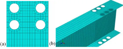
The subassemblies are modeled using a quadrilateral four-node shell element. It has six degrees of freedom per four-node, translations in the x, y and z directions, and rotations about x, y and z axes. Fig. 2a shows the typical finite element meshing, used in this study. A more refined mesh is employed for the regions near drilled holes which are critical zones and shown in Fig. 2b.
Fig. 2: Finite element meshing a) in the beam flanges and b) Three-dimensional model
3
2.3. Material Modeling
The modulus of elasticity is 2.05×10⁵ N/mm² and Poisson's ratio is 0.3. Elastoplastic analysis is carried out by ABAQUS finite element software using a S4R, a 4-node quadrilateral thick shell element with reduced integration. A nonlinear kinematic-isotropic hardening, combined with Ziegler's rule, has been assumed. Some material properties of beam flanges and web used in the analytical modeling are summarized in Table1[11].
Table. 1: Material properties of the beam and column [11].
Yield stress (N/mm²)
Tensile strength (N/mm²)
Maximum elongation
(%) Beam Flange 365 467 25.0 Beam Web 393 479 19.0 Column Flange 276 433 325 Column Web 298 443 30.5
2.4. Loading Protocol
The history of average deflection angle versus cyclic forced displacement at the free end of beam has been specified and presented in Table 2 [11].
Table. 2: Loading protocol [11].
1 cycle @ 0.01 rad
1 cycle @ 0.02 rad
1 cycle @ 0.03 rad
1 cycle @ 0.04 rad
3. Verifying the Results of Finite Element Analysis
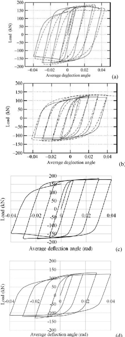
The results of finite element models should be verified with the experimental results. The models introduced in the previous sections, are analyzed using ABAQUS finite element software. The cantilever beam has been tested by M.Ohsaki et al. in the laboratory [11]. In this study the stated beam has been modeled and its analytical results have been verified with experimental values. The holes are applied in the flanges of beams. Fig. 3 shows the accuracy and consistency of finite element models. In Figure 3, the parts (a) and (b) have been experimentally obtained by other researchers. In the same figure, (c) and (d) are analytically obtained in this research using finite element modeling. According to this figure, the analytical results are well verified with the experimental tests for pre-Northridge and RBS connections.
(a)
(b)
(c)
(d)
Fig. 3: Load- deflection angle obtained by other researchers and in this research:
a and c) Pre-Northridge, respectively; b and d) RBS connections, respectively
Numerical Methods in Civil Engineering, Vol. 1, No.4, June.2017
4. Effect of Different Parameters on the Hysteresis
Responses
The subassembly models, described before, are analyzed and the effects of dimensions, positions and number of holes are investigated on the hysteresis curves and presented in the following sections.
4.1. The Effects of Hole Dimensions
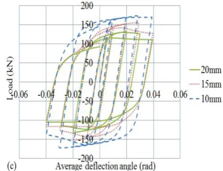
The holes with different dimensions have been studied and compared to achieve the best seismic behavior of DBS connection. The curves have been plotted for load (kN) versus rotation (rad) to compare DBS-N connections. The compared models have single-hole, double-hole and triple-hole patterns. According to the hysteresis curves presented in Fig. 4, the closer the hole diameterto the size proposed by AISC for RBS connections [12], the more uniform and symmetric the hysteresis curve of DBS. They indicate better seismic performance with the holes of 20 mm diameter.
Fig. 4: Hysteretic response of DBS-N with the holes of different dimension and number, a) DBS-single hole, b) DBS-double hole and
c) DBS-triple hole
4.2. The Effects of Hole Positions
According to the results obtained for the dimensions of holes, DBS-N-20 shows appropriate seismic performance in all three mentioned statuses. In order to study the hole position in the beam flanges, several samples with the hole diameter of 20 mm are considered all The investigation has been conducted on four samples in order to achieve the best hole position. According to the codes recommendations, the distance of beam plastic hinge from column face should be in the range of d/2 to d beam (d= depth of beam). Therefore, the holes are located in both sides of upper and lower flanges, in the distance between d/2 and d from column face.
In this study four models have been considered with the holes of 20 mm diameter in d/2, 5d/6, 7d/10 and d. The hysteresis curves of two models with single holes have been presented for d/2 and 7d/10 distances in Fig. 5a and for 5d/6 and d in Fig. 5b. The area under hysteresis curve indicates the dissipated energy of structure. It can be derived from hysteresis curves that the shorter the distance of the hole from column, the better the seismic performance of connection.
(a)
5
(b)
Fig. 5: Hysteretic response of DBS, single hole, D=20mm in the hole situations of a) d/2 and 7d/10 and b) 5d/6 and d
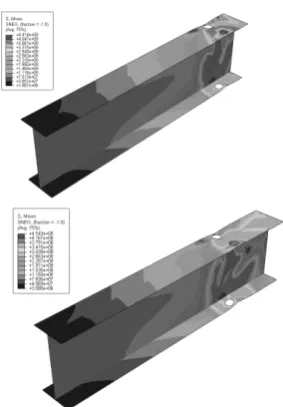
Von Mises stress contours are presented in Fig. 6; high stress region is displayed by red color. Fig. 7 shows the longitudinal strains at certain points on the compressive flanges of modeled beams. Pushover analysis has been applied to determine the location of formation of plastic hinge in the modeled beams. In this regard, the beam is subjected to the loads of 20, 40, 60, 80 and 95kN to extract the longitudinal strain of elements in the probable plastic hinge zone. The position of element with maximum strain shows the location of plastic hinge. The plastic hinge is formed in the region of maximum Von Mises stress. An appropriate solution should be found for the location of plastic hinge in order to improve the seismic performance of connection. According to Fig. 7, if the holes are farther from the connection, then the plastic hinge will move away from column face. The connections with the holes of minimum distance from column face have uniform hysteresis curves.
Fig. 6: Von Mises stresscontours for two drilled beam sections
Fig. 7: Longitudinal strains at the points on the compressive flange: a) DBS, single hole, D=20mm; b) DBS, double hole, D=20mm
4.3. The Effectof Hole Number
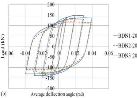
Hole number is of the most effective factor in the seismic performance of DBS connections. In order to understand the effect of various hole numbers, the dimensions of holes are studied considering equal diameters (DBS-N) for drilled samples. Fig. 8 shows the samples with 20 mm diameters in single, double and triple hole patterns. According to the obtained results, the samples with single hole show the best seismic performance.
Based on the hysteretic responses shown in Fig. 8, increasing the number of holes has a negative effect on the seismc performance of connection. The seismic performance of DBS-N1-20 connection, studied previously, has been compared with those of the connections with more number of holesand descending hole diameters. It is concluded that the single hole connection has better performance.
Numerical Methods in Civil Engineering, Vol. 1, No.4, June.2017
Fig. 8: Hysteretic response: a) DBS with various number and dimensions of holes; b)DBS-N with various number of holes
5. Conclusions
DBS connections can be implemented in the constructed and under construction structures. They also show good similarity with RBS connections regarding their seismic performances. For all these advantages, DBS connections can be recommended in the structures in the near future. Plastic hinge will occur in the beam, like in the RBS connections, by creating holes in the beam flanges.
In this research DBS connection has been studied numerically by finite element method. The obtained results are briefly summarized as follows:
Bringing closer the holes’ diameter of beam flanges in DBS connections to the shorter dimension of RBS connection will cause the increase of energy dissipation and improve the seismic performance.
In general, if the distance between the first hole and column face decreases in the plastic hinge zone, DBS connections behave as RBS ones and their hysteresis curves become symmetric.
Increasing the number of holes in the plastic hinge zone makes the energy dissipation decrease in the DBS connections and consequently downgrade their seismic performances.
Optimum performance is achieved in DBS connection by creating only one hole in both sides in upper and lower flanges of beam.
These results are based merely on numerical studies and computer simulations. To ascertain, experimental tests on DBS connections are definitely needed.
References
[1] Chen, S.J Yeh C.H., (1994), “Enhancement of ductility of steel beam-to-column connections for seismic resistance”, Presented at the SSRC task group meeting and technical section.
[2] Moore, K.S, Malley, J.O, Engelhardt M.D, (1996), “Design of reduced beam section (RBS) moment connections”, Steel Tips, Structural Steel Education Council. Moraga, CA.
[3] Grubbs, K.V, (1997), “The Effect of the Dogbone Connection on the Elastic Stiffness of Steel Moment Frame”, a thesis submitted in partial fulfillment of the degree of Master of Science in Engineering, University of Texas at Austin, Austin, Texas.
[4] Rea, D. Clough, R.W, Bouwkamp, J.G., (1969), “Damping Capacity of a Model Steel Structure”, Earthquake Engineering Research Center; University of California at Berkeley, Berkeley, CA, December, Report No. EERC, 69-14.
[5] Plumier, A., (1990), “New idea for safe structures in seismic zone”, IASE Symposium, Brussels.
[6] Iwankiw, N.R. Carter, C.J., (1996), “The Dogbone: A new idea to chew on modern steel construction”, AISC, Vol. 36, No. 4, April.
[7] Zekioglu, A. Mozaffarian, H. and Uang, C., (1997), “Moment frame connection development and testing for the city of hope national medical center”, Proceedings Structures Congress XV, Portland, American Society of Civil Engineers.
[8] Engelhardt, M.D, Winneberger, T. Zekany, A.J, and Potyraj, T.J., (1996), “The dogbone connection Part II”, Modern Steel Construction; 36(8), 46-55.
[9] Engelhardt, M.D. Winneberger, T. Zekany, A.J, and Potyraj, T.J., (1998), “Experimental investigation of dogbone moment connections”, Modern Steel Construction; 35(4), 128-139.
[10] ABAQUS, Version 6.11 Documentation. ABAQUS Inc.
(2011).
[11] Ohsaki, M. Tagawa, H. Pan, P., (2009), “Shape optimization of reduced beam section under cyclic loads”, Journal Constructional Steel Research; 65, 1511-1519.
[12] American Institute of Steel Construction, (2010), “Prequalified Connections for Special and Intermediate Steel Moment Frame for Seismic Applications”, Chicago: AISC.
[13] Federal Emergency Management Agency, (2000), “Interim Guidelines: Evaluation, Repair, Modification and Design of Steel Moment Frames”, Washington DC: October, FEMA-267.
[14] Federal Emergency Management Agency, (2000),
“Recommended seismic design criteria for new steel moment-frame buildings”, Washington DC: October, FEMA-350.
[15] Federal Emergency Management Agency, (1997), “NEHRP
commentary on the guidelines for the seismic rehabilitation of buildings”, Washington DC: October, FEMA-274.
[16] Lee, C.H, Kim, J.H., (2007), “Seismic design of reduced beam section (RBS) steel moment connections with bolted web attachment”, Journal Constructional Steel Research; 63, 52