Strojniški vestnik - Journal of Mechanical Engineering 53(2007)6, 409-419 U D K - UDC 532.58
S tr o k o v n i članek - Speciality paper (1.04)
Dinamično odzivanje valjaste cevi na gibajoči se tlak
T he Dynamic Response of a Cylindrical Tube under the Action of a Moving Pressure
Bahador Saranjam1 - Kambiz Bakhshandeh1 - Mohammad-Hassan Kadivar2 ('M UT University, Iran; 2Shiraz University, Iran)
V predstavljeni raziskavi smo z metodo končnih elementov preučili dinamično odzivanje valjastih cevi na notranji gibajoči se tlak, ki potuje s stalno hitrostjo. V prispevku predpostavljamo, da je debelina sten cevi povsod enaka in majhna v primerjavi s povprečnim polmerom cevi. Moč gibajočega se tlaka in hitrosti čela tlaka je stalna. Izračunali smo dinamično obnašanje različnih valjev z različnimi razmerji med dolžino in premerom. Glede na ugotovitve naše raziskave ima analiza dinamike bistven pomen za hitrost visokega tlaka. V naši raziskavi smo določili dve novi zasnovi: faktor radialne dinamične povečave in dolgi del. Pokazali smo, da sta vrednost in obnašanje faktorja radialne dinamične povečave odvisna od razmerja med dolžino in premerom ter ju lahko razdelimo na tri območja. V primeru dolgega valja lahko obnašanje faktorja radialne dinamične povečave razdelimo na podkritično, prehodno in nadkritično območje. Po izsledkih naše raziskave se faktor radialne dinamične povečave giblje med 1,8 in 2,55 in je odvisen od dolžine valjev. Za analizo končnih elementov smo uporabili računalniški program Msc/Nastran.
© 2007 Strojniški vestnik. Vse pravice pridržane.
(K ljučne besede: gibanje tlaka, analize končnih elementov, faktor radialne dinamične povečave, valjaste cevi)
In this study the dynamic response o f cylindrical tubes subjected to an internal moving pressure, travelling at a constant velocity, has been investigated with the finite-element method. In this paper the tube's wall thickness is considered to be uniform throughout and small compared to the mean radius o f the tube. The intensity o f the moving pressure as well as the velocity o f the front is constant. The dynamic behaviour o f various cylinders with different length-to-diameter ratios is calculated. Based on this study, w e believe a dynamic analysis is essential fo r a high pressure velocity. In this study, two new concepts are defined: the radial dynamic magnification factor and the long member. We show that the value and behaviour o f the radial dynamic magnification factor are dependent on the length-to-diameter ratio and can be divided into two or three regions. For a long cylinder the behaviour o f the radial dynamic magnification fa c to r is divided into the under-critical, transition and overcritical regions. According to this study, the radial dynamic magnification factor changes from 1.8 to 2.55, depending on the length o f the cylinders. The Msc/Nastran software package was used fo r the finite-element analysis.
© 2007 Journal o f Mechanical Engineering. All rights reserved.
(Keywords: moving pressure, finite element analysis, dynamic magnification factor, cylindrical tube)
I
OUVOD 0 INTRODUCTION
Različne konstrukcije, od mostov do cest in cevovodov, so neprestano izpostavljene gibajočim se silam ali tlakom. Določanje dinamičnega učinka gibajočega se brem ena na elastične konstrukcije, posebno na cevi, je zelo zapletena naloga. Vemo, da je dinamični učinek obremenitve na steno cevi velik, kadar se čelo tlaka z veliko hitrostjo giblje vzdolž cevi. Analiza mirovanja stene cevi je smiselna, kadar se čelo tlaka giblje z majhno hitrostjo. Za velike
hitrosti pa analiza mirovanja ne zadošča in je treba izvesti analizo dinamike.
P ro b le m se stav o v , ki so iz p o s ta v lje n i različnim obrem enitvam , se pogosto pojavlja v sodobnem inženirstvu. Primeri takšnih struktur so: mostovi, žerjavi in letališke steze f 1], Večinoma so bili doslej ti sistemi pri uporabi tram ov in plošč oblikovani z uporabo metod analize in približka ([2] do [4]). Nekaj avtorjev je sicer pripravilo podlage za izpeljavo dinam ičnih enačb, ki bi veljale za splošna ogrodja, ki nosijo potujoča bremena, a so v praksi upoštevali le modele tram ov ali plošč. Zato so nerešeni problem splošnih ogrodij, še posebej ogrodij iz v alja stih p lo šč , ki so izp o stav ljen i gibajočemu se tlaku, spregledali, ali mu posvetili premalo pozornosti. Tang [5] je raziskoval dinamično odzivanje polzaprte valjaste cevi, k ije izpostavljena notranjemu gibajočemu se tlaku. Tudi Faria [6] je z metodo končnih elementov analiziral tresenje lupine valja, na katerega deluje gibajoča se sila ali masa. Preučeval je učinek krivine valja. Opravljenih je bilo nekaj raziskav gibajočega se tlaka, še posebej za prim er končnega valja.
V naši raziskavi sm o preučili dinam ično obnašanje različnih valjastih cevi, na katere deluje gibajoči se tlak. Predpostavili smo, da se čelo tlaka giblje s stalno hitrostjo vzporedno z osjo cevi, in da je moč tlaka povsod enaka. Upoštevali smo različne valje z različnimi razmerji med dolžino in premerom. Dinamično obnašanje vsakega valja smo izračunali za širok razpon mogočih hitrosti. Definirali smo dve novi zasnovi, faktor radialne dinamične povečave in dolgi del.
F a k to r r a d ia ln e d in a m ič n e p o v e č a v e (FRDP) je razm erje m ed radialnim dinam ičnim u p o g ib o m in ra d ia ln im s ta tič n im u p o g ib o m . Iz p e lja li in p rim e rja li sm o fa k to rje ra d ia ln e dinam ične povečave za različn a razm erja m ed d o lž in o in p re m e ro m . S fa k to rje m ra d ia ln e dinam ične povečave sm o uvedli še eno zam isel, dolgi del. Tega smo definirali kot valj, pri katerem j e dinam ična povečava stalna glede na določen ra z p o n h i t r o s t i tla k a . Z a a n a liz o k o n č n ih elem entov smo uporabili računalniški program M sc/N astran.
1POSTOPEKDOLOČITVE FAKTORJA RADIALNE DINAMIČNE POVEČAVE
Postopek, ki smo ga uporabili za določitev faktorja radialne dinamične povečave, je vključeval
However, for high velocities a static analysis is not enough and a dynamic analysis must be used.
The problem o f structures subjected to vary ing loads is often encountered in modem engineer ing. A few examples o f such structures are bridges, overhead cranes and airport mnaways [1]. However, most studies to date have modelled these systems using analytical and approximate methods for the cases o f beams or plates ([2] to [4]). A few authors have provided a basis for the derivation o f the dy namic governing equations o f general shells carrying moving loads but have, in practice, implemented beam or plate models only. Hence, the important problem of general shells, in particular cylindrical panels, sub jected to a moving pressure has been overlooked or received little attention. Tang [5], investigated the dynamic response o f a semi-finite cylindrical tube under an internal moving pressure. Also, Faria [6] analyzed the vibration o f a cylinder’s panel resulting from a moving force or mass using the finite-element method. The studies focused on the cylinder’s curva ture effect. There have been few studies on moving pressures in cylinders, especially for finite cylinders.
In this study, the dynamic behaviour o f vari ous cylindrical tubes under the action o f a moving pressure is investigated. The pressure front is as sumed to be moving with constant velocity, parallel to the axis o f the tube, and the pressure intensity is assumed to be uniform. Various cylinders with dif ferent length-to-diameter ratios are considered. The dynamic behaviour o f each cylinder is calculated for a wide range o f speeds. Two new concepts are de fined: the radial dynamic magnification factor and the long member.
The radial dynam ic m agnification factor (RDMF) is the ratio o f the radial dynamic deflection to the radial static deflection. The radial dynamic magnification factor for various length-to-diameter ratios is extracted and compared. Also, with use of RDMF behaviour another concept is defined, i.e., the long member. The long member is defined as a cylinder for which the dynamic magnification has a constant behaviour in a part o f the pressure speed range. The M sc/Nastran software package was used for the finite-element analysis.
1 PROCEDURE FOR DETERMINING THE RADIAL DYNAMIC MAGNIFICATION FACTOR
Sl. 1. Valj, izpostavljen gibajočemu se tlaku
Fig. 1. Cylinder subjected to a moving pressure
m e to d o k o n č n ih elem en to v . F a k to r rad ialn e dinam ične povečave smo izračunali za valj, ki je izpostavljen gibajočemu se tlaku (Sl. 1). Čelo tlaka se giblje od leve strani valja s stalno hitrostjo V in velikostjo P .
Faktor radialne dinam ične povečave smo določili kot radialni dinamični upogib valja deljen z radialnim statičnim upogibom na sredini dolžine valja.
Pri naši raziskavi smo obravnavali različne valje s stalnim razm ajem med debelino in premerom
(h/D) in različne vrednosti razmerja med dolžino in
premerom (L!D). Dolžina valjev L se spreminja od
L = D do L = 20D. Za vsak valj smo izračunali statični
radialni upogib. Izračune smo izvedli za različne vrednosti razm eija med dolžino in premerom (L!D)
ter stalno razmerje med debelino stene in premerom
(h/D = 0,05).
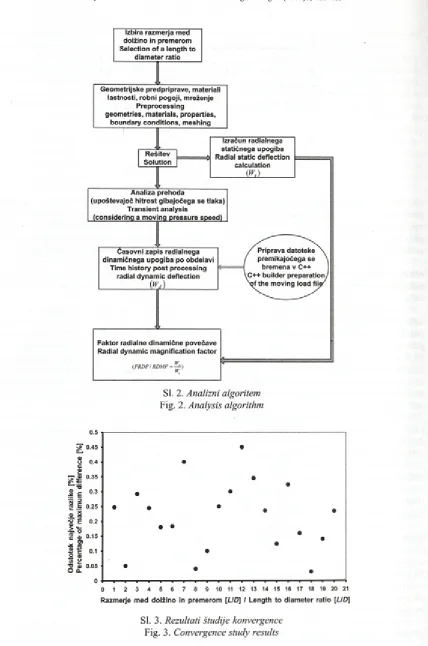
Izračunali smo radialne dinamične upogibe valjev za različne hitrosti gibajočega se tlaka. Z delitvijo dinamičnih upogibov valjev z izračunanim statičnim upogibom dobimo FRDP za različne valje in za določen razpon hitrosti gibajočega se tlaka. Slika 2 prikazuj e analizni algoritem, ki smo ga uporabili v raziskavi. V tem postopku smo upoštevali širok razpon hitrosti, da smo lahko prepoznali obnašanje faktorja FRDP za vsak valj posebej.
Izračun končnih elem entov smo izvedli z računalniškim programom Msc/Nastran [7]. Izračun linearne elastičnosti prehoda smo izvedli za potrebe izračuna odziva sestava na gibajoči se tlak bremena. Pri vseh izračunih smo v smislu izotropne elastičnosti ravninske n ap eto sti uporabili m etodo končnih e lem en to v s s ta n d a rd n im 8 -v o z lišč n im izoparametričnim elementom s štirimi stranicami.
Z a d o se g a n je p rim e rn e g o sto te m reže, potrebne za izboljšanje natančnosti rezultatov, smo
factor using the finite-element (FE) method. The radial dynamic magnification factor is calculated for a cylin der subjected to a moving pressure (Figure 1). The pressure front begins to move from the left-hand side of cylinder with a constant speed V and magnitude Pt].
The radial dynamic magnification factor is defined as the radial dynamic deflection o f the cylin der divided by the radial static deflection o f the cyl inder at mid-length.
In this study various cylinders with a con stant thickness-to-diameter ratio (h/D) and various values o f the length-to-diameter (L/D) ratio are con sidered. The length L o f the cylinders changes from
L = D to L = 20D. For each cylinder the static radial deflection is calculated. The computations were per formed for different values o f the length-to-diameter
(L/D) ratio and a constant thickness-to-diameter ra
tio (h/D = 0.05).
The radial dynamic deflections o f the cylin ders were calculated for various moving pressure speeds. With dividing these dynamic deflections by the calculated radial static deflection, the RDMF for various cylinders was obtained for a particular mov ing pressure speed range. The analysis algorithm that was used is shown in Figure 2. This procedure was performed for a wide range o f velocities in order to investigate the RDMF behaviour o f each cylinder.
The finite-element calculation was made with the Msc/Nastran software package [7]. A transient linear elastic calculation was carried out to calculate the structural response to a moving pressure load. The FE method with a standard 8-node quadrilateral iso-parametric element was used in the context o f plane-stress isotropic elasticity for all the computa tions.
suit-Sl. 2. Analizni algoritem
Fig. 2. Analysis algorithm
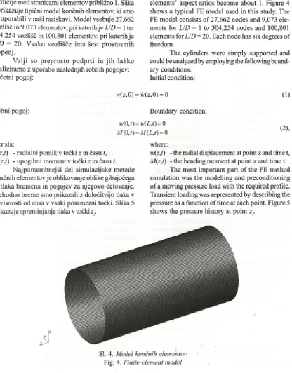
0 1 2 3 4 5 6 7 8 9 10 11 12 13 14 15 16 17 18 19 20 21 R azm erje m ed d o lžin o in prem erom [UD] I Length to diam eter ratio [UD]
Sl. 3. Rezultati študije konvergence
uporabili različne gostote mreže po dolžini vsakega valja. Zgoščevanje mreže smo ponavljali, dokler ni postala razlika med zaporednimi rezultati manjša od 0,5% . Slika 3 prikazuje končna odstopanja faktorjev dinam ične povečave pri različnih razmerjih med dolžino in premerom.
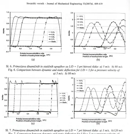
Gostoto radialne mreže smo izbrali tako, daje razmerje med stranicami elementov približno 1. Slika 4 prikazuje tipični model končnih elementov, ki smo ga uporabili v naši raziskavi. Model vsebuje 27.662 vozlišč in 9.073 elementov, pri katerih je U D = 1 ter 304.254 vozlišč in 100.801 elementov, pri katerihje
L /D = 20. V sako vozlišče im a šest prostostnih
stopenj.
V alji so p rep ro sto p o d p rti in jih lahko analiziram o z uporabo naslednjih robnih pogojev: Začetni pogoj:
able mesh density to improve the accuracy o f the results. Densifying the mesh was iteratively repeated until the difference between consecutive results became less than 0.5%. In Figure 3 the final discrep ancy o f the dynamic magnification factor for vari ous length-to-diameter ratios is shown.
The radial mesh density was chosen so that elem ents’ aspect ratios become about 1. Figure 4 shows a typical FE model used in this study. The FE model consists o f 27,662 nodes and 9,073 ele ments for LID = 1 to 304,254 nodes and 100,801 elements for LID — 20. Each node has six degrees o f freedom.
The cylinders were simply supported and could be analyzed by employing the following bound ary conditions:
Initial condition:
w(z, 0) = w(z, 0) = 0 (1)
Boundary condition: = w(L,t) = 0
= M(L,t) = 0 (
2
),R obni pogoj:
ufO,/) 11/(0,/) kjer sta:
w(z,t) - radialni pomik v točki z in času t,
M(z,t) - upogibni moment v točki z in času t.
N ajpom em bnejši del simulacijske metode končnih elementov je oblikovanje oblike gibajočega se tlaka bremena in pogojev za njegovo delovanje. Prehodno breme smo prikazali z določitvijo tlaka v odvisnosti od časa v vsaki posamezni točki. Slika 5 prikazuj e spreminj anj e tlaka v točki z..
where:
w(z,t) - the radial displacement at point z and time t,
M(z,t) - the bending moment at point z and time t.
The most important part o f the FE method simulation was the modelling and preconditioning of a moving pressure load with the required profile. Transient loading was represented by describing the pressure as a function o f time at each point. Figure 5 shows the pressure history at point z..
KggSSS
S filis i
SI. 4. Model končnih elementov
Sl. 5. Porazdelitev tlaka
Fig. 5. Pressure distribution
Prikaz sprememb tlaka v vsaki točki valja je določen kot:
This pressure history for each point o f the cylinder was defined as:
P (z ,t) = P0u ( t - z / V ) (3),
kjer so:
P - velikost tlaka,
u - skočna funkcija,
V - hitrost gibajočega se tlaka.
Ta tlak smo uporabili pri modelu končnih elementov s približno 1000 odseki v razdobju L/ V, ki je enako trajanju vsake posamezne simulacije.
Metodo končnih elementov lahko uporabimo tudi za neenakom erni prerez tram a [8]. Analizni algoritem, ki ga uporabimo v tem primeru, je podoben algoritmu iz slike 2. Kakor smo pokazali z našo študijo, ponuja metoda končnih elementov veliko natančnost, zato lahko to metodo uporabimo za izračun gibajočega se tlaka ali sile na različnih sestavih.
Za potrebe analize prehoda smo uporabili Newmarkovo metodo [7] in z njo izvedli integracijo po času, pri kateri so znani vsi parametri za tn, hkrati pa lahko t izračunamo z uporabo naslednje enačbe gibanja:
where:
Pg - pressure magnitude
n - step function
V - travelling speed o f the pressure
This pressure was applied to the finite-ele ment model with about 1000 segments over a time period o f L/V, equal to the duration o f each simula tion.
The FE method has also been used for a non- uniform cross-sectional beam [8], The analysis al gorithm used for this beam is similar to Figure 2. As shown in that study, the accuracy o f the FE method is excellent, and so this method can be used for cal culating a moving pressure or force in various struc tures.
F or tran sien t analysis the N ew m ark [7] method is used to integrate with respect to time; where all the parameters for tn are known, tn+l can be calculated using the following equation o f motion:
m^ + c^ + k^ f“ (4),
kjer so: M matrika mase, C matrika dušenja, Kmatrika to g o s ti, F“ , v e k to r z u n a n je g a b re m e n a , <jn^
pospešek pri tn+l, qn+l hitrost pri tnH in qnl] pomik pri ?n+r
Ocene vrednosti za qn+l, <j„+l in qn+l podamo takole:
=q'n
9*+i =?; <7„+i = R kjer je At časovna razlika, y in /?p a sta stalnici; q’n,
qn, m atriko M* in vektor F i z r a č u n a m o z naslednjimi enačbami:
where M is the mass matrix, C is the damping matrix, K is the stiffness matrix, F“' is the external load vec tor, qn+l is the acceleration at tn+i, qn+lis the velocity at t and qn+i is the displacement at tn+y
The estimates o f qn+v qi:rl and qn+iare given by:
!^ +A t2
+r'4n*At (5)>
[*_l -T? r e s id u a l
1
K:?"“ = F Z -C q n- K q:
M' = M + C/Ar +
K ß A t2^ = 9 „ + (l-y )? „ A /
. (\-2j3)ij At2
<in = ? „ + q,A‘ + ---~ —
2 REZULTATI 2 RESULTS
Skupine valjev imajo premer D = 20 mm, The cylinder groups have a diameter!)=20 mm, debelino h = 1 mm, modul elastičnosti £ = 2 1 0 GPa, in thickness h = 1 mm, elastic modulus £ = 210 GPa, gostoto p = 7800 kg/m3 (preglednica 1). and density p= 7800 kg/m3 (Table 1).
Preglednica 1. Lastnosti materiala
Table 1. Material Properties
M odul elastičnosti Poissonovo število Gostota Elastic modulus Poisson’s ratio Density
E u P
GPa kg/m3
jeklo
steel 2 1 0 0,3 7800
Dolžina L valjev iz te skupine niha med L = D in L = 20D. Račune smo izvedli za različne vrednosti razmerja med dolžino in premerom (L/D)
in stalno razmerje med debelino in premerom (h/D = 0,05).
Č elo tlak a se začne g ib ati na levi strani valja s staln o in te n ziv n o stjo ( £ 0 = 445 M Pa). Na v sak i sto p n ji izraču n a je h itro st čela tlak a stalna.
S lik i 6 in 7 p rik a z u je ta s p re m in ja n je rad ialn eg a d in am ičn eg a u p o g ib a na ra z ličn ih točkah ( Wd) valja, deljenega z radialnim statičnim upogibom ( W ) glede na lego gibajočega se tlaka. Analiza m irovanja valja je smiselna le takrat, ko se čelo tlaka giblje z majhno hitrostjo. V primeru velike hitrosti p a m oram o uporabiti analizo dinamike. Glede na om enjena diagram a je največji radialni dinamični upogib pri majhni hitrosti tlaka blizu statičnemu upogibu (m aksim alni faktor radialne dinamične povečave: Najv. FRDP»1,0), toda ob zv ečan i h itro s ti fa k to r d in a m ič n e p o v e č a v e preseže statični upogib.
Kakor kažejo slike, se lega pojava Najv. FRDP spreminja s povečano hitrostjo tlaka in dolžino valja. Pri majhni hitrosti je njegova lega na levi strani valja, pri povečani hitrosti tlaka pa se ta lega premakne proti desni strani valja. Kakor kaže slika 6, je pri hitrosti 5 m/s faktor pri dolžini 0,1 (0,1 /, ), pri hitrosti 80 m/s pa se, v primeru L/D = 3, premakne na levo
The length L of the cylinders in this group changes from L = D to L = 20D. The computations were performed for different values o f the length-to- diameter ratio (L/D) and a constant thickness-to-di- ameter ratio (h/D = 0.05).
The pressure front begins to move form the left-hand side o f the cylinder with a constant inten sity (P0 = 445 MPa). The velocity of the pressure front is constant at each calculation stage.
P o l o ž a j b r e m e n a / d o l ž i n a v a l j a P o s i t i o n o f l o a d / c y l i n d e r l e n g t h
(a)
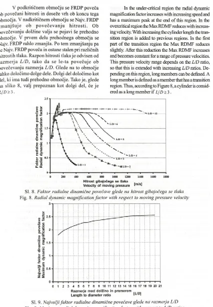
SI. 6. Primerjava dinamičnih in statičnih upogibov za L/D = 3 pri hitrosti tlaka: a) 5 m/s; b) 80 m/s
Fig. 6. Comparison between dynamic and static deflection fo r L/D = 3 fo r a pressure velocity of: a) 5 m/s; b) 80 m/s
SI. 7. Primerjava dinamičnih in statičnih upogibov za L/D = 7 pri hitrosti tlaka: a) 5 m/s, b)120 m/s
Fig. 7. Comparison between dynamic and static deflection fo r L/D = 7 at a pressure velocity of: a) 5 m/s, b) 120 m/s
stran valja (0,7L). V primeru L/D = 7 se faktor pojavi pri dolžini 0,8L in se nanaša na hitrost 120 m/s. Najv. F R D P se p ri n izk i h itro s ti d e ja n sk o p rib liž a največjem u statičnem u upogibu, m edtem ko ob zvečani hitrosti tlaka ta faktor začne zaostajati za gibajočim se tlakom. To zaostajanje se ob povečani hitrosti poveča.
K akor vidim o na sliki 8, je sprem injanje največjega faktoija za gibajoči se tlak pri različnih hitrostih odvisno od razm erja L/D. Pri majhnem razmetju L/D to obnašanje lahko razdelimo na dve območji: podkritično in nadkritično. Pri velikem razm erju L/D p a ga razdelim o n a tri obm očja: podkritično, prehodno in nadkritično območje.
a velocity of 80 m/s, for L/D = 3, is shifted to the left-hand side ofthe cylinder (0.1 L). This value for L/D=7 is 0.8T and relates to 120 m/s. Indeed the Max RDMF at low velocity is near to the location of the maximum static deflection, but with increasing the pressure velocity the Max RDMF has a delay with respect to the position of the moving pressure. This delay time increases with increasing velocity.
As can be seen from Figure 8, the variation o f M ax RDMF for a m oving pressure at various speeds is dependent o f the L/D ratio. For low L/D
ratios this behaviour can be divided into two re gions: under-critical and overcritical. For high L/D
V podkritičnem obm očju se FRDP poveča ob povečani hitrosti in doseže vrh ob koncu tega območja. V nadkritičnem obm očju se Najv. FRDP z m a n jš u je ob p o v e č e v a n ju h itr o s ti. Ob povečevanju dolžine valja se pojavi še prehodno območje. V prvem delu prehodnega območja se Najv. FRDP rahlo zmanjša. Po tem zm anjšanju pa se Najv. FRDP poveča in ostane stalen pri različnih hitrostih tlaka. Razpon hitrosti tlaka je odvisen od ra z m e rja L/D , ta k o da se le -ta p o v e č u je ob povečevanju razm erja L/D. Glede na to območje lahko določimo dolge dele. Dolgi del določimo kot del, ki ima tudi prehodno območje. Tako je, glede na sliko 8, valj prepoznan kot dolgi del, če je
L/D> 3.
In the under-critical region the radial dynamic magnification factor increases with increasing speed and has a maximum peak at the end o f this region. In the overcritical region the Max RDMF reduces with increas ing velocity. With increasing the cylinder length the tran sition region is added to previous regions. In the first part of the transition region the Max RDMF reduces slightly. After this reduction the Max RDMF increases and becomes constant for a range of pressure velocities. This pressure velocity range depends on the L/D ratio, so that this is extended with increasing L/D ratios. De pending on this region, long members can be defined. A long member is defined as a member that has a transition region. Thus, according to Figure 8, a cylinder is consid ered as a long member if L/D > 3.
SI. 8. Faktor radialne dinamične povečave glede na hitrost gibajočega se tlaka
Fig. 8. Radial dynamic magnification factor with respect to moving pressure velocity
R a z m e r j e m e d d o l ž i n o in p r e m e r o m L e n g t h t o d i a m e t e r r a t io
SI. 9. Največji faktor radialne dinamične povečave glede na razmerja L/D
Glede na sliko 8 postaja ob povečevanju razmerja med dolžino in premerom prehodno območje daljše in bolj gladko, medtemko se nadkritično območje zmanjšuje. Obnašanje faktoija radialne dinamične povečave je v primem majhnega razmerja L/D podobno obnašanju v primem tramov [8], Pri tramu, izpostavljenemu delovanju gibajočih se bremen, je obnašanje faktorja razdeljeno na dve območji, podkritično in nadkritično, nikjer pa ne zasledimo prehodnega območja.
Slika 9 prikazuje največji faktor radialne dinamične povečave glede na ra zm erja!//). Pri vseh v aljih je d inam ični u pogib v ečji od statičnega upogiba. Dinamični upogib j e v primem, k o je L/D = 1, približno 1,8 krat večji od statičnega upogiba. Ta vrednost se, ob povečanju razmerja med dolžino in premerom do L/D = 20, poveča na 2,55.
3 SKLEP
Pri m ajhni hitrosti tlaka zadostuje analiza mirovanja, pri povečani hitrosti pa je ključna analiza prehoda.
Faktor radialne dinamične povečave pri valju je odvisen od razmerja med dolžino in premerom. Ob povečevanju razmerja L/D se faktor poveča od 1,8 do 2,55.
Pri dolgem valju lahko obnašanje največjega faktorja radialne dinamične povečave razdelimo na tri obm očja: podkritično, p rehodno in nadkritično območje. Nasprotno pa je pri kratkem valju prehodno območje zelo majhno in ga lahko zanemarimo. Treba je še dodati, da ob povečanju dolžine valja nadkritično območje postane majhno v prim erjavi z dragim a območjema. V primeru, koje L/D > 3, ima FRDP stalno obnašanje pri različnih hitrostih in tako lahko dolge dele določimo kot valje, pri katerih je dolžina trikrat daljša od premera. Obnašanje kratkih valjev pa je podobno obnašanju tramov, izpostavljenih delovanju gibajočih se bremen.
According to Figure 8, w ith an increasing length-to-diam eter ratio the transition region be comes longer and smoother, whereas the overcritical region becomes smaller. The behaviour o f the RDMF for a low L/D ratio is similar to that for beams [8], For a beam under the action o f moving loads the RDMF behaviour consists o f two regions, the under-criti cal and the overcritical, and there is no sign o f a transition region.
The Max RDMF with respect to L/D ratios is shown in Figure 9. For all cylinders the dynamic de flection is higher than the static deflection. The dy namic deflection for L/D = 1 is about 1.8 times greater than the static deflection. This value increases to 2.55 when the length-to-diameter ratio increases up to Z/D = 20.
3 CONCLUSION
With a low pressure velocity a static analy sis is adequate, but with increasing velocity a tran sient analysis is essential.
The radial dynamic magnification factor in a cylinder depends on the length-to-diameter ratio. With an increasing L/D ratio the RMDF changes from 1.8 to 2.55.
In a long cylinder, the M ax RD M F behav iour can be d ivided into three regions: under- critical, transition and overcritical. In contrast, in a short cylinder, the tran sitio n region is very sm all and can be elim inated. H ow ever, w hen in creasing the length o f the cylinder the overcritical region is sm all com pared to the other regions. F o r L/D > 3, the R M D F is constant w ith a change in the speed, and as such long m em bers are de fined as the cylinders w here the length is three tim es the diam eter. The short cy lin d ers’ behav iour is sim ilar to beam s, under the action o f m ov ing loads.
4 LITERATURA 4 REFERENCES
[1] Fryba, L. (1999) Vibration o f solids and structures under moving loads, ThomasTelford, Third edition. [2] Pesterev A. V., Yang B., Bergman L. A., Tan C. A. (2003) Revisiting the moving force problem , J o f sound
and vibration, 261(2003), pp. 75-91.
[3] Gbadeyan J. A., Oni S. T. ( 1995), Dynamic behaviour o f beams and rectangular plates under moving loads,
J o f Sound and Vibration, 182 (1995), pp. 677-695.
[5] Tang S. (1996) Dynamic response o f a tube under moving pressure, Journal o f Engineering Mechanics
Division, 91(1996), pp. 96-122
[6] Faria A. R. (2004) Finite element analysis o f the dynamic response o f cylindrical panels under traversing loads, European Journal o f Mechanics A/Solids, 23(2004), pp. 677-687
[7] Manual (2004) MSC/NASTRAN for Windows: Quick start guide, MacNeal-Schwendler Corporation.
[8] Saranjam B, Bakhshandeh K., Kadivar M. H. (2006) Dynamic behaviour o f a beam with non-uniform linear varying cross-section under moving load, Strojnicky Časopis-Joumal o f Mechanical Engineering, 57(2006) C. l,p p . 45-58.
Naslova avtoijev: Bahador Saranjam Kambiz Bakhshandeh
Center za zračno-momariške raziskave Univerza MUT
Shiraz, Iran
prof. dr. Mohammad-Hassan Kadivar Oddelek za strojništvo
Šola za tehniške vede Univerza Shiraz Shiraz, Iran
Authors’ Addresses: Bahador Saranjam Kambiz Bakhshandeh Air Naval Research Center MUT University
Shiraz, Iran
Kambiz@Bakhshandeh. ir
Prof. Dr. Mohammad-Hassan Kadivar Department o f Mechanical engineering School o f Engineering
Shiraz University Shiraz, Iran
Prejeto:
Received: 1 8 .7 .2 0 0 6
Sprejeto:
Accepted: 2 5 .4 .2 0 0 7