Vol. 2, No. 3, pp. 189-196, July (2019)
Control Law Design with Dead-beat Property in
Continuous-Time Dynamical Systems
Valiollah Ghaffari
††
Department of Electrical Engineering, Persian Gulf University, Bushehr, Iran
In this paper, an open-loop control scheme is developed to design of a dead-beat control effort in the high order continuous-time LTI systems. The dead-beat control is really a finite-time control law. In this method, the input signal is manually selected such that the output signal becomes constant in a finite time. In the LTI systems, having known the step response, a control signal could be exactly selected such a way that the control objective would be met in a finite time. For this goal, the dead-beat control problem is firstly investigated in a standard first order system. Then a similar problem is studied in the second order systems. Finally a general design framework would be developed to obtain a dead-beat control policy in the high order continuous-time systems. In the proposed method, the control design problem is deliberately converted into the solution of a linear matrix equation. Therefore the control signal would be determined via the solution of an algebraic equation. The suggested procedure has been successfully applied in some continuous-time LTI systems. The simulation results show the effectiveness of the proposed control method for designing of a finite-time control law in the continuous-time LTI systems.
Article Info
Keywords:
Continuous-time systems, Dead-beat control, LTI control system, Posicast control. Article History:
Received 2018-08-07 Accepted 2019-02-11
I.
I
NTRODUCTIONTheoretically the control synthesis problems have been mainly investigated in closed loop control system. The closed loop control schemes may have some advantages over the corresponded open-loop ones. These briefly includes improvement of the stability property and also robustness with respect to the parameter changes. But some extra costs should be paid due to existence of some measurement sensors and control design [1]. Hence sometimes the open-loop control scheme would be interested especially when there is not any disturbance and or parameter uncertainty. In the control literatures, some open-loop control policies have been proposed in the dynamical systems as well as dead-beat control [2, 3], iterative learning control (ILC) [4] , input shaping control [5] and signal correction control technique [6].
The dead-beat control problem is firstly investigated in the discrete-time SISO systems [7]. In the discrete-time system,
the relation between input and output is simply described by a difference equation rather than differential one. Hence, in the discrete-time version of the dead-beat control, the input signal would be designed such a way that the input signal (control effort) becomes exactly zero after some sampling times. Then the output signal would become a constant value. This problem is also studied in the multivariable systems [8]. The dead-beat property would be very important in some control applications as well as grid connected systems [9, 10], electric machines [11-13], active power filter [14], electronic convertors [15, 16] and aerospace vehicles [17].
The discrete-time control signal may be converted into a continuous-time signal by adding a zero-order hold (ZOH) element but it may make some reconstruction errors [18-20]. Although the dead-beat control problem is essentially suggested in the discrete-time systems but such a control concept can be also extended to the continuous-time ones [2, 21, 22]. In other word, in the continuous-time dead-beat control, the input signal is manually selected such that the output signal becomes constant in a finite time. It seems that a dead-beat control would be a finite-time control law in the open-loop control structures. But the concept of the *Corresponding Author: [email protected]
Tel: +98-77-33442269, Fax: +98-77-33445188
Dep. of Elec. Eng., Persian Gulf University, Bushehr, Iran
A
B
S
T
R
A
C
finite-time control system has been mainly studied in the closed loop schemes [23].
Recently several control methods have been suggested in the literatures to realize the finite settling-time control in a continuous-time control system. These mainly includes the Posicast control and feedback control using bang-bang or hysteresis element [23-25]. In the second order systems, the Posicast control policy is designed to obtain dead-beat response with zero initial condition [3, 26, 27]. Then it is extended to nonzero initial condition [28]. Similar problem is also studied in the fractional order systems [29] and sampled-data system [30].
In a typical continuous-time system, sometimes there exists a piecewise continuous-time control signal which provides a dead-beat response. This point motivates the author to study the dead-beat control law in the high order continuous-time systems. For achieving this goal, the dead-beat problem is firstly investigated in the standard first order system. Then it is studied in the second order systems. Finally a general framework would be developed to obtain a dead-beat control policy in the high order continuous-time systems. Hence some benefits of the proposed method can be listed as the following:
1- This method is inherently an open loop structure. Thus it does not need any further sensor.
2- The control system structure is a very simple. Thus the control signal is directly determined.
3- It does not need to run the control system continuously. The controller is active in a finite time.
4- This method can be efficiently used in some control applications like guidance problem.
5- The control system design procedure is very simple for the designer.
6- In the proposed method, the dead-beat control is constructed via using of some pulse-shape signals. Therefore the main contribution of this paper concentrates on designing of a dead-beat control law in the continuous-time LTI systems. The suggested method would be an open-loop scheme which is realized with combination of some sequences of the pulse signals.
The rest of this paper is organized as follows: In the next section, some mathematical notations and symbols are addressed. Then in the sections 3, the problem formulation and main result of the paper is presented. The application of proposed method is studied in some numerical examples in the section 4. Finally some concluding remarks are placed in the last section.
II.
M
ATHEMATICALN
OTATIONSThroughout this paper, the symbol denotes the unit step signal, is the unit step response in a continuous-time LTI system. The system’s input and output
denote by and respectively. The star symbol ∗ is used for the convolution integral. The symbol also states the Laplace operator. The mathematical definition of the dead-beat control in the continuous-time form can be expressed as follows:
Definition 1: The response of a continuous-time system would have a dead-beat property, if its output is a constant value after a finite-time. In a simple word, it can be mathematically written as follows:
= ∀ > (1)
The switching-time would be exactly the settling-time of the continuous-time system (1). The standard first order system can be described with the following transfer function:
= (2)
where is the system gain and > 0 is the time-constant of the LTI system (2). The standard second order system is written as the following:
= (3)
where 0 < < 1 is the damping ratio and ! > 0 is the natural frequency of the second order system (3). A typical high order continuous-time LTI system with all real-poles may be described as follows:
= "# " … "%
&# & … & , ' < ( (4)
In the equation (4), the positive parameters )* indicates poles of the open-loop system (4) and the coefficients +, determines the system’s zeros. It is assumed that the poles are simple and stable. The system’s zeros may be some real or complex numbers. Next, the dead-beat problem is formulated in the continuous-time system. Then some technical results would be proposed.
III.
P
ROBLEMF
ORMULATIONIn some continuous-time control applications, an open-loop control law design may be interested. Sometimes it may be found a piecewise continuous-time control signal which provides a dead-beat response. The input signals in form of the pulse structure would be concerned in this paper. Then a sequence of the pulse signals would be considered as a control signal. The parameters of such pulse signal is determined such that the system output would be constant after a finite time. Therefore, in this section, the dead-beat problem is mainly investigated in the standard first order and second order systems. Then a general framework will be developed to obtain dead-beat control policy in the high order continuous-time systems (4). For this purpose, firstly, a first order system is considered. Such a system is a simple continuous-time one. Then it can be easily analyzed. In the next lemma, a simple dead-beat control law is addressed. Lemma 1: In the first order system (2), if the switching-time
is deliberately selected as = . .( /1 +
signal:
= 31 + 4 0 < <0 < 0
1 ≥ (5)
where 4 can be any positive constant and the switching-time would be the settling-time of the system (2).
Proof: In the first order system (2), the unit step response can be found as follows:
= /1 − 7982 (6)
It is easy check that the response due to an input
signal = 1 + 4 − 4 − would be computed
as the following:
= 1 + 4 − 4 − (7)
By substitution of the switching-time = . .( /1 + 12, the system response , ≥ would be obtained as follows:
= 1 + 4 /1 − 7982 − 4 /1 − 78:8;9 2 (8) Then a dead-beat response = , ≥ would be appeared. It completes the proof.
Remark 1: In the lemma 1, the constant 4 would be an independent variable. It can be shown that the switching-time could be selected as an independent variable when the
constant parameter 4 is chosen as 4 = / 8;9− 127 .
Remark 2: It is seen that in the first order system (2), the dead-beat response would not be unique. Then in order to obtain a dead-bead response via the lemma 1, there are too many choices for selection of the constant 4.
Similarly such idea can also be used in a second order system to obtain a dead-beat response. Consider the standard second order system (3). It can be shown that the following control signal will provide a dead-beat response in the standard second order system (3):
= <
0 < 0
=> 0 < < ?
1 ≥ ?
(9)
In the control literature, the control signal (9) is referred as the Posicast control law [3]. In the input signal there exist two terms @? and ? which are defined as follows:
@?≝ 7 BC
D#:C and
?≝ H
They denote the maximum overshoot and peak-time respectively due to unit step response in the standard second order system (3). Next, the dead-beat problem would be investigated in a general LTI systems.
Assumption 1: In the continuous-time LTI systems (4), assume that the parameters )* are some real and positive ones and the unit step response is represented as the following form:
=
I4J+ 4 7&#K+ 4 7& K+ ⋯ + 4 7& KM (10) In the equation (10), for the stability purpose, it is assumed that the coefficients )* must be some positive ones. Remark 3: The high order LTI system (4) can be mathematically decomposed into some first order subsystems. Then a dead-beat control signal can be designed for each subsystem by using of the Lemma 1. It does not guarantee that a linear combination of the designed control signals, for the first order subsystems, would provide a dead-beat response in the high order system (4).
The remark 3 can be checked with a simple parallel system like = + . For this purpose, assume that and are some dead-beat control signals for the subsystem and respectively. Let select a linear combination of the mentioned signal like = N + O . Then by using of the convolution integral and impulse response properties, the system output due to the input can be written as follows:
= .7 P Q ∗ = .7 P Q + .7 P Q ∗
IN + O M
Then it can be simplified as the following:
= N.7 P Q ∗ + O.7 P Q ∗ +
N.7 P Q ∗ + O.7 P Q ∗
The signal is designed based on the parameters of the subsystem . Then the third term has not dead-beat property. A similar justification can be existed for the signal in the subsystem . Therefore the linear combination of the signals and would not provide a dead-beat response in the LTI system . Hence it is necessary to develop a general framework for designing of dead-beat control signal in the LTI system (4).
In the first order and second order systems, the mentioned results about the dead-beat response may be seem simple. Having known the step response of a general LTI system , the dead-beat response could be also investigated in the high order continuous-time system. Hence the main result of this paper will be concentrated on selection of a dead-beat control law in the general LTI systems. The proposed results will be presented in the next theorem.
Theorem 1: Consider the assumption 1 holds and the unit step response is described by the equation (10). In the LTI system (4), for some known positive constants )* and switching-times *, R = 1, 2, … , (, 0 < < … < , if there exist some positive constants U*, R = 1, 2, … . ( such that the equation VW = ℬ admits a feasible solution W. where the matrix V and two vectors W and ℬ are given as:
V = Y
&#K#− 1 &#K − &#K#
& K#− 1 & K − & K# ⋯
&#K − &#K :#
& K − & K:#
⋮ ⋱ ⋮
W = Y U U ⋮ U
\, ℬ = Y &#K
& K
⋮
& K
\
Then with selection of the following input signal :
= U + U − U − +
U]− U − + U^− U] − ] + ⋯ +
U − U −
(11)
the continuous system (4) would have a dead-beat response. Proof: Considering the well-known superposition principle, the output of the LTI system (4) can be mathematically computed as follows:
= U + U − U − + U]−
U − + U^− U] − ] + ⋯ +
U − U −
(12)
The term U denotes the steady state value of the input signal . Then without loss of generality, the term U can be assumed to be a constant value. Hence in term of the step response parameters, the system response could be computed as:
= U I4J+ 4 7&#K+ 4 7& K+ ⋯ + 4 7& KM +
U − U I4J+ 4 7&#K7K# + 4 7& K7K# + ⋯ +
4 7& K7K#M − + U]− U I4J+ 4 7&#K7K + 4 7& K7K + ⋯ + 4 7& K7K M − + U
^−
U] I4J+ 4 7&#K7K_ + 4 7& K7K_ + ⋯ +
4 7& K7K_M − ] + ⋯ + U − U I4J+
4 7&#K7K + 4 7& K7K + ⋯ + 4 7& K7K M −
In order to have a dead-beat response, the system response would be constant one after a finite time (i.e. for > ). Then the system response , > can be computed as:
= U I4J+ 4 7&#K+ 4 7& K+ ⋯ + 4 7& KM +
U − U I4J+ 4 7&#K7K# + 4 7& K7K# + ⋯ +
4 7& K7K#M +
U]− U I4J+ 4 7&#K7K + 4 7& K7K + ⋯ +
4 7& K7K M +
U^− U] I4J+ 4 7&#K7K_ + 4 7& K7K_ + ⋯ +
4 7& K7K_M
⋮
+ U − U I4J+ 4 7&#K7K + 4 7& K7K + ⋯ +
4 7& K7K M , >
By rearranging and taking some simplifications, it can be written as follows:
= 4JU + 4 7&#KIU + U − U &#K#+
U]− U &#K + ⋯ + U − U &#K M + 4 7& KIU +
U − U & K#+ U]− U & K + ⋯ + U − U & K M +4] 7&_KIU + U − U &_K#+ U]− U &_K + ⋯
+ U − U &_K M ⋮
+4 7& KIU + U − U & K#+ U]− U & K + ⋯ +
U − U & K M , >
It is clear that the system response , > would be a constant value 4JU when the following equations simultaneously hold:
U + U − U &#K#+ U]− U &#K + ⋯ + U − U &#K = 0 U + U − U & K#+ U]− U & K + ⋯ + U − U & K = 0
⋮
U + U − U & K#+ U]− U & K + ⋯ + U − U & K = 0 The pervious equations can be rewritten as follows: U I1 − &#K#M + U I &#K#− &#K M + U]I &#K − &#K_M + ⋯
+ U I &#K :#− &#K M + U &#K = 0 U I1 − & K#M + U I & K#− & K M + U]I & K − & K_M + ⋯
+ U I & K :#− & K M + U & K = 0 ⋮
U I1 − & K#M + U I & K#− & K M + U]I & K − & K_M + ⋯ + U I & K :#− & K M + U & K = 0
Therefore, these equations would lead to the matrix equations VW = ℬ. It completes the proof.
Remark 4: In this paper, it is assumed that the conditions )*> 0 and 0 < < … < simultaneously hold. Then the rows of the matrix V would be independent. Hence the matrix V would be a non-singular. Therefore theequations VW = ℬ would always have a unique solution.
Remark 5: In the theorem 1, the switching-times *, R = 1, 2, … . ( would be some design parameters which selected by the designer. There are many choices for selection of the switching-times * but the only limitation would be expressed as 0 < < … < . Hence many control signals with dead-beat property can be obtained in the high order LTI system (4). In the theorem 1, the term denotes the settling-time. Furthermore dense selection of switching-times *’s usually leads to larger overshoot and also control effort. Hence a reasonable trade-off between the parameters of the system response as well as the settling-time, maximum overshoot and the maximum value of the control signal should be taken into account in a typical control problem. This issue is usually accomplished throughout solving of an optimization problem with some nonlinear constraints.
considered in the step response .
Remark 8: In the theorem 1, a model based and open-loop control law is addressed to provide dead-beat property. The open-loop stabilization methods can be helpful to design an efficient control law. Hence the results of the theorem 1 can be used in a cascaded system like ` . Then the subsystem ` is selected such that the some undesired poles of the subsystem like complex or repetitive can be vanished. Therefore the dead-beat control design would be used in a simplified LTI system ` .
Remark 9: In the theorem 1, some reasonable restrictions as well as the asymptotic stability, non-complex and non-repetitive poles are considered in order to formulate the control problem. A similar method can be also suggested to design of dead-beat control policy in the high order LTI system with the complex and repetitive poles.
IV.
S
IMULATIONR
ESULTSIn this section, the proposed procedure is applied in some dynamical systems in order to obtain a dead-beat control law. Example 1: Consider a first order continuous-time system with = 1 and a = 1 as follows:
= + 11 (13)
Let select the constant parameter 4 = 0.3. By applying of the result of the lemma 1, the switching-time can be
exactly calculated as = .( /]]2 = 1.4663. Due to the system uncertainty, the switching-time may not be precisely determined. Hence, in the numerical simulation, amount of 20% uncertainty is considered about the calculated switching-time . In the simulation of continuous-time system, the time increment sets as 0.01 seconds.
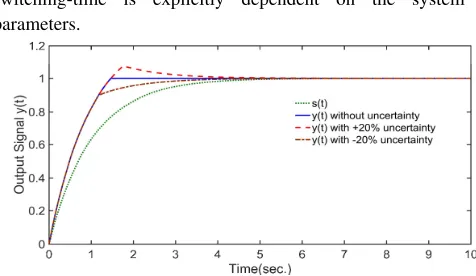
The simulation results are shown in the figures 1 and 2. It is seen that in a finite times (i.e. 1.4663 seconds), the system response would be constant one. The switching-time is explicitly dependent on the system parameters.
Fig. 1. The system response in the example 1
Fig. 2. The control signal in the example 1
In the figure 1, it is seen that although the exact dead-beat response would be disappeared in the case of uncertainty. But the system response is closely maintained around the dead-beat response. This property would be interested in some control applications as well as a guidance problems and power convertors. Therefore the proposed control law can be imagined a robust method in the presence of the uncertainty. Example 2: Consider the following 4th order system:
In the LTI system (14), the unit step response can be computed as follows:
= 2 − 2 7 K+ 3 7K− 4 7^K+ 7]K (15) It is seen that the step response parameters can be found as the following:
) = 2, ) = 1, )]= 4, )^= 3, 4J= 2 , 4 = −2 , 4 = 3, 4]= −4 and 4^= +1
In the proposed control method, the switching-times are design parameters. Let select the steady state value Ue= 1 and the switching-times as = 2, = 3, ]= 4 and
^= 5. Then, by applying of the theorem 1, the control signal parameters are exactly calculated as follows:
U = 1.2482, U = 0.9469, U]= 1.0027 and U^= 1.0 In the simulation of continuous-time system, the time-increment is taken as 0.01 seconds. The simulation results are shown in the figures 3 and 4. Furthermore the control signal will be analytically constructed as follows:
The control signal is also depicted in the figure 4. In the example 2, the settling-time is deliberately set as 5 seconds. In the figure 3, it is seen that the system response would be exactly constant after 5 seconds. This method would be useful when no uncertainty exists and the system parameters are some known and fixed values.
=
k^ _J _jJ]e ]eJ ^j^(14)
= 1.2482 − 0.3013 − 2 + 0.0558 − 3 − 0.0027 − 4
investigated in a typical mechanical system.
control input as follows
l
The mechanical system parameters are selected as follows: '
Then the transfer function
An application of the remark 8 may be useful in this example. For this purpose, the compensator block
chosen as
using of the Posicast control law as addressed in the equation (9), the control signal can be constructed for the cascaded system
Fig. 3. The dead
Fig. 4. The control signal
Next, the application of the proposed method is investigated in a typical mechanical system.
Example 3: Consider the following mechanical system
Fig
It can be shown that the transfer function between the control input
as follows [1]:
=
mn=
l
l# o #
The mechanical system parameters are selected as follows: ' = 1 p,
= 1 q/',
Then the transfer function
=
s t.] tAn application of the remark 8 may be useful in this example. For this purpose, the compensator block
chosen as `
using of the Posicast control law as addressed in the equation (9), the control signal can be constructed for the cascaded
system `
The dead-beat response
. The control signal
Next, the application of the proposed method is investigated in a typical mechanical system.
: Consider the following mechanical system
Fig. 5. A typical mechanical system
be shown that the transfer function between the and the output
=
l o _
l o
The mechanical system parameters are selected as follows:
, ' = 1 p,
, ]= 1 q/',
Then the transfer function
].^ ^ ] t s J.eJ u
An application of the remark 8 may be useful in this example. For this purpose, the compensator block
= 2.985
susing of the Posicast control law as addressed in the equation (9), the control signal can be constructed for the cascaded
. The system response
beat response in the example 2
. The control signal in the example 2
Next, the application of the proposed method is investigated in a typical mechanical system.
: Consider the following mechanical system
mechanical system
be shown that the transfer function between the and the output can be determined
_ _7 o
The mechanical system parameters are selected as follows:
, = 5 q/' ,
, O = 4 q/'/
would be found as:
J.ejej s J. vujs
An application of the remark 8 may be useful in this example. For this purpose, the compensator block `
s t.] t s J.eJ u
].^ ^ J.ejej
using of the Posicast control law as addressed in the equation (9), the control signal can be constructed for the cascaded
. The system response
in the example 2
in the example 2
Next, the application of the proposed method is
: Consider the following mechanical system [1]:
mechanical system [1]
be shown that the transfer function between the can be determined
The mechanical system parameters are selected as follows:
,
/ would be found as:
.uje
An application of the remark 8 may be useful in this example.
` is simply eJ u
ejej . Then by
using of the Posicast control law as addressed in the equation (9), the control signal can be constructed for the cascaded is shown in Next, the application of the proposed method is
:
be shown that the transfer function between the can be determined
An application of the remark 8 may be useful in this example. is simply
. Then by
using of the Posicast control law as addressed in the equation (9), the control signal can be constructed for the cascaded is shown in
the figure 6. It is seen that t
dead-beat response while the step response of the mechanical system has consistently oscillatory behavior.
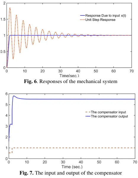
The input and output of the compensator is shown in figure 7. The compensator output is applied to the mechanical system.
In these examples, the simulation results verify the effectiveness of the suggested finite
the continuous
In the continuous
selected such that the control goal would be met in a finite-time. The control synthesis problem may be converted to an algebraic matrix equation. Then the dead
signal would be determ
The proposed control law is a model based method for designing of the dead
very efficient when a mathematical model exists for a dynamical system. The suggested approach is use
control examples to show the effectiveness of the method.
The author would like to thank Dr. Paknosh Karimaghaee with the school of Electrical and Computer Engineering, Shiraz University for his valuable comments which improve the paper.
the figure 6. It is seen that t
beat response while the step response of the mechanical system has consistently oscillatory behavior.
Fig. 6. Responses of the mechanical system
Fig. 7. The input and output of the compensator
The input and output of the compensator is shown in figure 7. The compensator output is applied to the mechanical
In these examples, the simulation results verify the effectiveness of the suggested finite
continuous-time systems.
V.
C
In the continuous-time LTI systems, a control signal can be selected such that the control goal would be met in a time. The control synthesis problem may be converted to an algebraic matrix equation. Then the dead
signal would be determined via solving the algebraic equation. The proposed control law is a model based method for designing of the dead-beat control policy. Hence it would be very efficient when a mathematical model exists for a dynamical system. The suggested approach is use
control examples to show the effectiveness of the method.
A
CKNOWLEDGEMENTThe author would like to thank Dr. Paknosh Karimaghaee with the school of Electrical and Computer Engineering, Shiraz University for his valuable comments which improve
e paper.
the figure 6. It is seen that the proposed method provides a beat response while the step response of the mechanical system has consistently oscillatory behavior.
Responses of the mechanical system
The input and output of the compensator
The input and output of the compensator is shown in figure 7. The compensator output is applied to the mechanical
In these examples, the simulation results verify the effectiveness of the suggested finite-time control technique in
time systems.
C
ONCLUSIONtime LTI systems, a control signal can be selected such that the control goal would be met in a time. The control synthesis problem may be converted to an algebraic matrix equation. Then the dead
ined via solving the algebraic equation. The proposed control law is a model based method for
beat control policy. Hence it would be very efficient when a mathematical model exists for a dynamical system. The suggested approach is use
control examples to show the effectiveness of the method.
CKNOWLEDGEMENT
The author would like to thank Dr. Paknosh Karimaghaee with the school of Electrical and Computer Engineering, Shiraz University for his valuable comments which improve he proposed method provides a beat response while the step response of the mechanical system has consistently oscillatory behavior.
Responses of the mechanical system
The input and output of the compensator
The input and output of the compensator is shown in figure 7. The compensator output is applied to the mechanical
In these examples, the simulation results verify the time control technique in
ONCLUSION
time LTI systems, a control signal can be selected such that the control goal would be met in a time. The control synthesis problem may be converted to an algebraic matrix equation. Then the dead-beat control ined via solving the algebraic equation. The proposed control law is a model based method for
beat control policy. Hence it would be very efficient when a mathematical model exists for a dynamical system. The suggested approach is used in some control examples to show the effectiveness of the method.
CKNOWLEDGEMENT
The author would like to thank Dr. Paknosh Karimaghaee with the school of Electrical and Computer Engineering, Shiraz University for his valuable comments which improve he proposed method provides a beat response while the step response of the mechanical
The input and output of the compensator
The input and output of the compensator is shown in figure 7. The compensator output is applied to the mechanical
In these examples, the simulation results verify the time control technique in
time LTI systems, a control signal can be selected such that the control goal would be met in a time. The control synthesis problem may be converted beat control ined via solving the algebraic equation. The proposed control law is a model based method for
beat control policy. Hence it would be very efficient when a mathematical model exists for a d in some control examples to show the effectiveness of the method.
[2] O. J. M. Smith, "Posicast control of damped oscillatory
[3] J. Y. Hung, "Feedback control with Posicast," IEEE
[4] D. A. Bristow, M. Tharayil, and A. G. Alleyne, "A survey of
[5] W. Singhose, D. Kim, and M. Kenison, "Input shaping
[6] S. Paul, A. Halder, and A. K. Nath, "Deadbeat Contro
[7] K. Ogata, Discrete
[8]
[9] Y. Atia and M. M. Salem, "Novel deadbeat power control
[10] C. Deng, Z. Shu, Y. Xia, N. Chen, T. Wang, and H. Ma,
[12
[13] C. Li, R. N. Dean, J. Y. Hung, and
[14] W. Jiang, X. Ding, Y. Ni, J. Wang, L. Wang, and W. Ma,
[15] Y. He, H. S.
[16] A. Mushi, S. Nagai, H. Obara, and A. Kawamura, "Fast and [1] O. Katsuhiko, Modern control engineering, 5 ed. New
Jersey: Prentice
[2] O. J. M. Smith, "Posicast control of damped oscillatory systems," Proceedings of the IRE, vol. 45, pp. 1249 1957.
[3] J. Y. Hung, "Feedback control with Posicast," IEEE Transactions on industrial electronics, vol. 50, pp. 94 2003.
[4] D. A. Bristow, M. Tharayil, and A. G. Alleyne, "A survey of iterative learning control," IEEE Control Systems, vol. 26, pp. 96-114, 2006.
[5] W. Singhose, D. Kim, and M. Kenison, "Input shaping control of double
Journal of Dynamic Systems, Measurement, and Control, vol. 130, p. 034504, 2008.
[6] S. Paul, A. Halder, and A. K. Nath, "Deadbeat Contro Dynamics of Inverted Pendulum using Signal Correction Technique," European Journal of Advances in Engineering and Technology, vol. 4, pp. 255
[7] K. Ogata, Discrete
Prentice-Hall Englewood, 1995.
[8] A. T. Azar and F. E. Serrano, "Deadbeat control for multivariable discrete time systems with time varying delays," Chaos modeling and control systems design, Springer, pp. 97
[9] Y. Atia and M. M. Salem, "Novel deadbeat power control strategy for grid connected systems," Journal of Electrical Systems and Information Technology, vol. 2, pp. 242 2015.
[10] C. Deng, Z. Shu, Y. Xia, N. Chen, T. Wang, and H. Ma, "Three-phase photovoltaic grid
based on current deadbeat
International Conference on Power System Technology, pp. 2864-2870, 2014.
[11] J. Zou, W. Xu, and C. Ye, "Improved Deadbeat Control Strategy for Linear Induction Machine," IEEE Transactions on Magnetics, vol. 53, pp. 1
[12] J. FENG, C. XIA, H. WANG, and Y. YAN, "Improved deadbeat predictive current control strategy of permanent magnet synchronous motors," Advanced Technology of Electrical Engineering and Energy, vol. 8, p. 001, 2015.
[13] C. Li, R. N. Dean, J. Y. Hung, and
"Feedback posicast control for micromachined electrostatic actuators," Micro & Nano Letters, vol. 11, pp. 722 2016.
[14] W. Jiang, X. Ding, Y. Ni, J. Wang, L. Wang, and W. Ma, "An Improved Deadbeat Control for a Three Three-Line A
Compensation," IEEE Transactions on Power Electronics, vol. 33, pp. 2061
[15] Y. He, H. S.
boundary control with second
reduce the system order for deadbeat controller in grid-connected inverter," IEEE Transactions on Power Electronics, vol. 31, pp. 2638
[16] A. Mushi, S. Nagai, H. Obara, and A. Kawamura, "Fast and robust nonlinear deadbeat current control for boost converter," IEEJ Journal of Industry Applications, vol. 6, pp.
R
EFERENCE[1] O. Katsuhiko, Modern control engineering, 5 ed. New Jersey: Prentice-Hall Englewood, 2010.
[2] O. J. M. Smith, "Posicast control of damped oscillatory systems," Proceedings of the IRE, vol. 45, pp. 1249
[3] J. Y. Hung, "Feedback control with Posicast," IEEE Transactions on industrial electronics, vol. 50, pp. 94
[4] D. A. Bristow, M. Tharayil, and A. G. Alleyne, "A survey of iterative learning control," IEEE Control Systems, vol. 26, pp.
, 2006.
[5] W. Singhose, D. Kim, and M. Kenison, "Input shaping control of double-pendulum bridge crane oscillations," Journal of Dynamic Systems, Measurement, and Control, vol. 130, p. 034504, 2008.
[6] S. Paul, A. Halder, and A. K. Nath, "Deadbeat Contro Dynamics of Inverted Pendulum using Signal Correction Technique," European Journal of Advances in Engineering and Technology, vol. 4, pp. 255
[7] K. Ogata, Discrete-time control systems, 2 ed. New Jersey: Hall Englewood, 1995.
A. T. Azar and F. E. Serrano, "Deadbeat control for multivariable discrete time systems with time varying delays," Chaos modeling and control systems design, Springer, pp. 97-132, 2015.
[9] Y. Atia and M. M. Salem, "Novel deadbeat power control r grid connected systems," Journal of Electrical Systems and Information Technology, vol. 2, pp. 242
[10] C. Deng, Z. Shu, Y. Xia, N. Chen, T. Wang, and H. Ma, phase photovoltaic grid
based on current deadbeat
International Conference on Power System Technology, pp. 2870, 2014.
[11] J. Zou, W. Xu, and C. Ye, "Improved Deadbeat Control Strategy for Linear Induction Machine," IEEE Transactions on Magnetics, vol. 53, pp. 1-4, 2017.
] J. FENG, C. XIA, H. WANG, and Y. YAN, "Improved deadbeat predictive current control strategy of permanent magnet synchronous motors," Advanced Technology of Electrical Engineering and Energy, vol. 8, p. 001, 2015.
[13] C. Li, R. N. Dean, J. Y. Hung, and
"Feedback posicast control for micromachined electrostatic actuators," Micro & Nano Letters, vol. 11, pp. 722
[14] W. Jiang, X. Ding, Y. Ni, J. Wang, L. Wang, and W. Ma, "An Improved Deadbeat Control for a Three
Line Active Power Filter With Current
Compensation," IEEE Transactions on Power Electronics, vol. 33, pp. 2061-2072, 2018.
[15] Y. He, H. S.-H. Chung, C. N. boundary control with second
he system order for deadbeat controller in connected inverter," IEEE Transactions on Power Electronics, vol. 31, pp.
2638-[16] A. Mushi, S. Nagai, H. Obara, and A. Kawamura, "Fast and robust nonlinear deadbeat current control for boost verter," IEEJ Journal of Industry Applications, vol. 6, pp.
EFERENCE
[1] O. Katsuhiko, Modern control engineering, 5 ed. New Hall Englewood, 2010.
[2] O. J. M. Smith, "Posicast control of damped oscillatory systems," Proceedings of the IRE, vol. 45, pp. 1249
[3] J. Y. Hung, "Feedback control with Posicast," IEEE Transactions on industrial electronics, vol. 50, pp. 94
[4] D. A. Bristow, M. Tharayil, and A. G. Alleyne, "A survey of iterative learning control," IEEE Control Systems, vol. 26, pp.
[5] W. Singhose, D. Kim, and M. Kenison, "Input shaping pendulum bridge crane oscillations," Journal of Dynamic Systems, Measurement, and Control, vol.
[6] S. Paul, A. Halder, and A. K. Nath, "Deadbeat Contro Dynamics of Inverted Pendulum using Signal Correction Technique," European Journal of Advances in Engineering and Technology, vol. 4, pp. 255-267, 2017.
time control systems, 2 ed. New Jersey: Hall Englewood, 1995.
A. T. Azar and F. E. Serrano, "Deadbeat control for multivariable discrete time systems with time varying delays," Chaos modeling and control systems design,
[9] Y. Atia and M. M. Salem, "Novel deadbeat power control r grid connected systems," Journal of Electrical Systems and Information Technology, vol. 2, pp. 242
[10] C. Deng, Z. Shu, Y. Xia, N. Chen, T. Wang, and H. Ma, phase photovoltaic grid-connected inverter with LCL based on current deadbeat control and PI control," International Conference on Power System Technology, pp.
[11] J. Zou, W. Xu, and C. Ye, "Improved Deadbeat Control Strategy for Linear Induction Machine," IEEE Transactions
4, 2017.
] J. FENG, C. XIA, H. WANG, and Y. YAN, "Improved deadbeat predictive current control strategy of permanent magnet synchronous motors," Advanced Technology of Electrical Engineering and Energy, vol. 8, p. 001, 2015.
[13] C. Li, R. N. Dean, J. Y. Hung, and G. T. Flowers, "Feedback posicast control for micromachined electrostatic actuators," Micro & Nano Letters, vol. 11, pp. 722
[14] W. Jiang, X. Ding, Y. Ni, J. Wang, L. Wang, and W. Ma, "An Improved Deadbeat Control for a Three
ctive Power Filter With Current
Compensation," IEEE Transactions on Power Electronics, 2072, 2018.
H. Chung, C. N.-M. Ho, and W. Wu, "Use of boundary control with second-order switching surface to he system order for deadbeat controller in connected inverter," IEEE Transactions on Power
-2653, 2016.
[16] A. Mushi, S. Nagai, H. Obara, and A. Kawamura, "Fast and robust nonlinear deadbeat current control for boost verter," IEEJ Journal of Industry Applications, vol. 6, pp. [1] O. Katsuhiko, Modern control engineering, 5 ed. New
[2] O. J. M. Smith, "Posicast control of damped oscillatory systems," Proceedings of the IRE, vol. 45, pp. 1249-1255,
[3] J. Y. Hung, "Feedback control with Posicast," IEEE Transactions on industrial electronics, vol. 50, pp. 94-99,
[4] D. A. Bristow, M. Tharayil, and A. G. Alleyne, "A survey of iterative learning control," IEEE Control Systems, vol. 26, pp.
[5] W. Singhose, D. Kim, and M. Kenison, "Input shaping pendulum bridge crane oscillations," Journal of Dynamic Systems, Measurement, and Control, vol.
[6] S. Paul, A. Halder, and A. K. Nath, "Deadbeat Control of Dynamics of Inverted Pendulum using Signal Correction Technique," European Journal of Advances in Engineering
time control systems, 2 ed. New Jersey:
A. T. Azar and F. E. Serrano, "Deadbeat control for multivariable discrete time systems with time varying delays," Chaos modeling and control systems design,
[9] Y. Atia and M. M. Salem, "Novel deadbeat power control r grid connected systems," Journal of Electrical Systems and Information Technology, vol. 2, pp. 242-256,
[10] C. Deng, Z. Shu, Y. Xia, N. Chen, T. Wang, and H. Ma, connected inverter with LCL control and PI control," International Conference on Power System Technology, pp.
[11] J. Zou, W. Xu, and C. Ye, "Improved Deadbeat Control Strategy for Linear Induction Machine," IEEE Transactions
] J. FENG, C. XIA, H. WANG, and Y. YAN, "Improved deadbeat predictive current control strategy of permanent magnet synchronous motors," Advanced Technology of Electrical Engineering and Energy, vol. 8, p. 001, 2015.
G. T. Flowers, "Feedback posicast control for micromachined electrostatic actuators," Micro & Nano Letters, vol. 11, pp. 722-726,
[14] W. Jiang, X. Ding, Y. Ni, J. Wang, L. Wang, and W. Ma, "An Improved Deadbeat Control for a Three-Phase ctive Power Filter With Current-Tracking Error Compensation," IEEE Transactions on Power Electronics,
M. Ho, and W. Wu, "Use of order switching surface to he system order for deadbeat controller in connected inverter," IEEE Transactions on Power
[16] A. Mushi, S. Nagai, H. Obara, and A. Kawamura, "Fast and robust nonlinear deadbeat current control for boost verter," IEEJ Journal of Industry Applications, vol. 6, pp. [1] O. Katsuhiko, Modern control engineering, 5 ed. New
[2] O. J. M. Smith, "Posicast control of damped oscillatory 1255,
[3] J. Y. Hung, "Feedback control with Posicast," IEEE 99,
[4] D. A. Bristow, M. Tharayil, and A. G. Alleyne, "A survey of iterative learning control," IEEE Control Systems, vol. 26, pp.
[5] W. Singhose, D. Kim, and M. Kenison, "Input shaping pendulum bridge crane oscillations," Journal of Dynamic Systems, Measurement, and Control, vol.
l of Dynamics of Inverted Pendulum using Signal Correction Technique," European Journal of Advances in Engineering
time control systems, 2 ed. New Jersey:
A. T. Azar and F. E. Serrano, "Deadbeat control for multivariable discrete time systems with time varying delays," Chaos modeling and control systems design,
[9] Y. Atia and M. M. Salem, "Novel deadbeat power control r grid connected systems," Journal of Electrical 256,
[10] C. Deng, Z. Shu, Y. Xia, N. Chen, T. Wang, and H. Ma, connected inverter with LCL control and PI control," International Conference on Power System Technology, pp.
[11] J. Zou, W. Xu, and C. Ye, "Improved Deadbeat Control Strategy for Linear Induction Machine," IEEE Transactions
] J. FENG, C. XIA, H. WANG, and Y. YAN, "Improved deadbeat predictive current control strategy of permanent magnet synchronous motors," Advanced Technology of
G. T. Flowers, "Feedback posicast control for micromachined electrostatic 726,
[14] W. Jiang, X. Ding, Y. Ni, J. Wang, L. Wang, and W. Ma, Phase Tracking Error Compensation," IEEE Transactions on Power Electronics,
M. Ho, and W. Wu, "Use of order switching surface to he system order for deadbeat controller in connected inverter," IEEE Transactions on Power
[16] A. Mushi, S. Nagai, H. Obara, and A. Kawamura, "Fast and robust nonlinear deadbeat current control for boost verter," IEEJ Journal of Industry Applications, vol. 6, pp.
311-319, 2017.
[17] K. Sawada, T. Ikawa, S. Shin, K. Kumagai, and H. Yoneda, "Continuous
Guided Vehicle," Transactions of the Society of Instrument and Co
[18] R. Kurosawa, "Continuous deadbeat control," IEEJ Transactions on Industry Applications, vol. 111, pp. 289 1991.
[19] G. Tallman and O. Smith, "Analog study of dead posicast control," IRE
vol. 4, pp. 14
[20] H. Katoh and Y. Funahashi, "Continuous control for sampled
Automatic Control, vol. 41, pp. 1478
[21] K. Tsumura, H. Morita, and Y
continuous time deadbeat control," American Control Conference, pp. 3190
[22] E. Nobuyama, S. Shin, and T. Kitamori, "Deadbeat control of continuous
on Decision and Control, pp. [23] Y. Hong, "Finite
class of controllable systems," Systems & control letters, vol. 46, pp. 231
[24] A. B. Chammas and C. T. Leondes, "On the finite time control of linear systems b
feedback," International Journal of Control, vol. 30, pp. 227-234, 1979.
[25] F. L. Lewis, D. Vrabie, and V. L. Syrmos, Optimal control: John Wiley & Sons, 2012.
[26] G. Cook, "An application of half Transa
1966.
[27] H. C. So and G. Thaler, "A modified posicast method of control with applications to higher
Transactions of the American Institute of Electrical Engineers, Part II: Applications a
320-326, 1960.
[28] J. A. Esquivel Cardenas and J. Ruiz Tello, "Posicast Control with Nonzero Initial Conditions," IEEE Latin America Transactions, vol. 6, 2008.
[29] E. Gonzalez, J. Hung, L. Dorcak, J. Terpak, and I. Petras, "Posicast control of a class of fractional
Open Physics, vol. 11, pp. 868
[30] K. Abidi, Y. Yildiz, and A. Annaswamy, "Control of Uncertain Sampled
Control Approach," IEEE Transactions on Automati Control, vol. 62, pp. 2597
department, persian gulf university. His research interes include robust and nonlinear control systems and hybrid control systems.
319, 2017.
[17] K. Sawada, T. Ikawa, S. Shin, K. Kumagai, and H. Yoneda, "Continuous-time Robust Deadbeat Control of Automatic Guided Vehicle," Transactions of the Society of Instrument and Control Engineers, vol. 49, pp. 246
R. Kurosawa, "Continuous deadbeat control," IEEJ Transactions on Industry Applications, vol. 111, pp. 289
[19] G. Tallman and O. Smith, "Analog study of dead posicast control," IRE
vol. 4, pp. 14-21, 1958.
[20] H. Katoh and Y. Funahashi, "Continuous control for
sampled-Automatic Control, vol. 41, pp. 1478
[21] K. Tsumura, H. Morita, and Y
continuous time deadbeat control," American Control Conference, pp.
3190-[22] E. Nobuyama, S. Shin, and T. Kitamori, "Deadbeat control of continuous-time systems: MIMO case," IEEE Conference on Decision and Control, pp.
[23] Y. Hong, "Finite-time stabilization and stabilizability of a class of controllable systems," Systems & control letters, vol. 46, pp. 231-236, 2002.
[24] A. B. Chammas and C. T. Leondes, "On the finite time control of linear systems b
feedback," International Journal of Control, vol. 30, pp. 234, 1979.
[25] F. L. Lewis, D. Vrabie, and V. L. Syrmos, Optimal control: John Wiley & Sons, 2012.
[26] G. Cook, "An application of half
Transactions on Automatic Control, vol. 11, pp. 556
[27] H. C. So and G. Thaler, "A modified posicast method of control with applications to higher
Transactions of the American Institute of Electrical Engineers, Part II: Applications a
326, 1960.
[28] J. A. Esquivel Cardenas and J. Ruiz Tello, "Posicast Control with Nonzero Initial Conditions," IEEE Latin America Transactions, vol. 6, 2008.
[29] E. Gonzalez, J. Hung, L. Dorcak, J. Terpak, and I. Petras, icast control of a class of fractional
Open Physics, vol. 11, pp. 868
[30] K. Abidi, Y. Yildiz, and A. Annaswamy, "Control of Uncertain Sampled-Data Systems: An Adaptive Posicast Control Approach," IEEE Transactions on Automati Control, vol. 62, pp. 2597
Valiollah Ghaffari
and PhD degrees in electrical engineering from Shiraz University, Shiraz, Iran in 2006, 2009 and 2014 respectively. He is currently assistant professor at electrical engineering department, persian gulf university. His research interes include robust and nonlinear control systems and hybrid control systems.
[17] K. Sawada, T. Ikawa, S. Shin, K. Kumagai, and H. Yoneda, time Robust Deadbeat Control of Automatic Guided Vehicle," Transactions of the Society of Instrument
ntrol Engineers, vol. 49, pp. 246
R. Kurosawa, "Continuous deadbeat control," IEEJ Transactions on Industry Applications, vol. 111, pp. 289
[19] G. Tallman and O. Smith, "Analog study of dead posicast control," IRE Transactions on Automatic Control,
21, 1958.
[20] H. Katoh and Y. Funahashi, "Continuous
-data systems," IEEE Transactions on Automatic Control, vol. 41, pp.
1478-[21] K. Tsumura, H. Morita, and Y. Saito, "Multiobjective continuous time deadbeat control," American Control Conference, pp. 3190-3194, 1997.
[22] E. Nobuyama, S. Shin, and T. Kitamori, "Deadbeat control time systems: MIMO case," IEEE Conference on Decision and Control, pp. 2110-2113, 1996.
time stabilization and stabilizability of a class of controllable systems," Systems & control letters, vol.
236, 2002.
[24] A. B. Chammas and C. T. Leondes, "On the finite time control of linear systems by piecewise constant output feedback," International Journal of Control, vol. 30, pp.
[25] F. L. Lewis, D. Vrabie, and V. L. Syrmos, Optimal control: John Wiley & Sons, 2012.
[26] G. Cook, "An application of half
ctions on Automatic Control, vol. 11, pp. 556
[27] H. C. So and G. Thaler, "A modified posicast method of control with applications to higher
Transactions of the American Institute of Electrical Engineers, Part II: Applications and Industry, vol. 79, pp.
[28] J. A. Esquivel Cardenas and J. Ruiz Tello, "Posicast Control with Nonzero Initial Conditions," IEEE Latin America Transactions, vol. 6, 2008.
[29] E. Gonzalez, J. Hung, L. Dorcak, J. Terpak, and I. Petras, icast control of a class of fractional
Open Physics, vol. 11, pp. 868-880, 2013.
[30] K. Abidi, Y. Yildiz, and A. Annaswamy, "Control of Data Systems: An Adaptive Posicast Control Approach," IEEE Transactions on Automati Control, vol. 62, pp. 2597-2602, 2017.
Valiollah Ghaffari
and PhD degrees in electrical engineering from Shiraz University, Shiraz, Iran in 2006, 2009 and 2014 respectively. He is currently assistant professor at electrical engineering department, persian gulf university. His research interes include robust and nonlinear control systems and hybrid [17] K. Sawada, T. Ikawa, S. Shin, K. Kumagai, and H. Yoneda, time Robust Deadbeat Control of Automatic Guided Vehicle," Transactions of the Society of Instrument
ntrol Engineers, vol. 49, pp. 246-254, 2013.
R. Kurosawa, "Continuous deadbeat control," IEEJ Transactions on Industry Applications, vol. 111, pp. 289
[19] G. Tallman and O. Smith, "Analog study of dead Transactions on Automatic Control,
[20] H. Katoh and Y. Funahashi, "Continuous-time deadbeat data systems," IEEE Transactions on
-1481, 1996.
. Saito, "Multiobjective continuous time deadbeat control," American Control
[22] E. Nobuyama, S. Shin, and T. Kitamori, "Deadbeat control time systems: MIMO case," IEEE Conference
2113, 1996.
time stabilization and stabilizability of a class of controllable systems," Systems & control letters, vol.
[24] A. B. Chammas and C. T. Leondes, "On the finite time y piecewise constant output feedback," International Journal of Control, vol. 30, pp.
[25] F. L. Lewis, D. Vrabie, and V. L. Syrmos, Optimal control:
[26] G. Cook, "An application of half-cycle Posicast," IEEE ctions on Automatic Control, vol. 11, pp. 556
[27] H. C. So and G. Thaler, "A modified posicast method of control with applications to higher-order systems," Transactions of the American Institute of Electrical nd Industry, vol. 79, pp.
[28] J. A. Esquivel Cardenas and J. Ruiz Tello, "Posicast Control with Nonzero Initial Conditions," IEEE Latin America
[29] E. Gonzalez, J. Hung, L. Dorcak, J. Terpak, and I. Petras, icast control of a class of fractional-order processes,"
880, 2013.
[30] K. Abidi, Y. Yildiz, and A. Annaswamy, "Control of Data Systems: An Adaptive Posicast Control Approach," IEEE Transactions on Automati
2602, 2017.
received the BS, MS and PhD degrees in electrical engineering from Shiraz University, Shiraz, Iran in 2006, 2009 and 2014 respectively. He is currently assistant professor at electrical engineering department, persian gulf university. His research interes include robust and nonlinear control systems and hybrid [17] K. Sawada, T. Ikawa, S. Shin, K. Kumagai, and H. Yoneda, time Robust Deadbeat Control of Automatic Guided Vehicle," Transactions of the Society of Instrument
R. Kurosawa, "Continuous deadbeat control," IEEJ Transactions on Industry Applications, vol. 111, pp. 289-295,
[19] G. Tallman and O. Smith, "Analog study of dead-beat Transactions on Automatic Control,
time deadbeat data systems," IEEE Transactions on
. Saito, "Multiobjective continuous time deadbeat control," American Control
[22] E. Nobuyama, S. Shin, and T. Kitamori, "Deadbeat control time systems: MIMO case," IEEE Conference
time stabilization and stabilizability of a class of controllable systems," Systems & control letters, vol.
[24] A. B. Chammas and C. T. Leondes, "On the finite time y piecewise constant output feedback," International Journal of Control, vol. 30, pp.
[25] F. L. Lewis, D. Vrabie, and V. L. Syrmos, Optimal control:
cycle Posicast," IEEE ctions on Automatic Control, vol. 11, pp. 556-559,
[27] H. C. So and G. Thaler, "A modified posicast method of order systems," Transactions of the American Institute of Electrical nd Industry, vol. 79, pp.
[28] J. A. Esquivel Cardenas and J. Ruiz Tello, "Posicast Control with Nonzero Initial Conditions," IEEE Latin America
[29] E. Gonzalez, J. Hung, L. Dorcak, J. Terpak, and I. Petras, order processes,"
[30] K. Abidi, Y. Yildiz, and A. Annaswamy, "Control of Data Systems: An Adaptive Posicast Control Approach," IEEE Transactions on Automatic