Coarsening in Solidification Processing
*Merton C. Flemings
Department of Materials Science and Engineering, Massachusetts Institute of Technology, Cambridge, MA 02139, USA
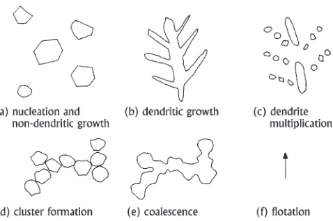
Coarsening manifests itself in solidification of metal alloys as 1) growth of larger particles or dendrite arms with simultaneous dissolution of smaller particles or arms (‘‘ripening’’), 2) filling in of spaces between particles or dendrite arms (‘‘coalescence’’) and 3) breakup of dendrites (‘‘dendrite multiplication’’). Ripening of dendrites during solidification results in the well known dependency of dendrite arm spacing on cooling rate or local solidification time. If initial dendritic grain size is sufficiently small, the grains may spheroidize and then grow non-dendritically during isothermal holding in the liquid-solid zone. Dendrite multiplication results from convection combined with rapid cooling during initial stages of dendritic solidification. If the new grains thus formed are sufficiently high in number density, subsequent growth of these grains is non-dendritic. There is engineering interest today in finding the most reliable and economic ways of achieving such a high initial grain density, either by thermo-mechanical means or by grain refinement.
(Received December 20, 2004; Accepted February 22, 2005; Published May 15, 2005)
Keywords: coarsening, ripening, coalescence, dendrite multiplication
1. Introduction
The term ‘‘coarsening’’ is used in this talk to refer to the growth, in a liquid-solid mixture, of solid regions of low curvature at the expense of regions of higher curvature. Coarsening manifests itself in solidification of metal alloys as 1) growth of larger particles or dendrite arms with simulta-neous dissolution of smaller particles or arms (‘‘ripening’’), 2) filling in of spaces between particles or dendrite arms (‘‘coalescence’’) and 3) breakup of dendrites (‘‘dendrite multiplication’’). Figures 1(a), (b), and (c) show schemati-cally the ripening during solidification of an equiaxed dendrite. Dendrite arms grow both as a result of increasing fraction solid as solidification proceeds, and by dissolution of smaller arms. At higher fractions solid, Fig. 1(c), coalescence becomes the dominant coarsening mechanism, as spaces between dendrite arms fill in. With sufficient time, at least for material with fine initial grain size, coarsening proceeds to such an extent that the dendrite gradually assumes a rosette-like structure, Figs. 2(a) and (b), and then spherical mor-phology, Fig. 2(c), which itself then coarsens, and may eventually coalesce, Figs. 3(a), (b), and (c). The third coarsening mechanism discussed in this paper is the breakup of dendrites initially formed, Fig. 4.
(a) (b) (c)
Fig. 1 Coarsening in dendritic solidification: a) structure early in solid-ification; b), c) structures later in solidification showing ripening and coalescence.
(a) (b) (c)
Fig. 2 Late stage coarsening of fine grain structures: a) partially coarsened structure, b) rosette-like structure after additional coarsening, c) spherical morphology resulting after longer coarsening.
(a) (b) (c)
Fig. 3 Coarsening of spherical morphology during solidification: a) structure early in solidification; b) structure later solidification, ripened; c) structure near the end of solidification, showing coalescence.
Fig. 4 Dendrite multiplication.
*The Fiftieth Gold Medalist of the Japan Institute of Metals, 2005
[image:1.595.307.547.309.413.2] [image:1.595.308.548.478.577.2] [image:1.595.48.289.617.717.2] [image:1.595.310.548.641.768.2]2. Dendrite Coarsening During Growth and Isothermal Holding
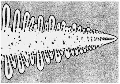
Studies of growing dendrite tips in transparent materials show how coarsening, and to some extent coalescence, begin just back from the tip, soon after the secondary dendrite arms form.1–3) An example is the succonitrile dendritic growth
experiment of Glicksman and co-workers,4)Fig. 5. Note that
the secondary arm spacing increases along the length of the dendrite, back from the tip. The increase results from the melting back of smaller arms (coarsening), and their eventual engulfment by the growing larger arms (coalescence). Direct evidence of coarsening in metallic alloys is seen by quenching samples at different local fractions solid.5) The dendrite arm spacing increases progressively during solid-ification as a result of both ripening and coalescence, as shown schematically in Figs. 1(a), (b), and (c).
Grains in castings and ingots of metal alloys range typically from several hundred microns to 10 mm or more in diameter, and possess a well formed internal dendritic structure. Coarsening of the internal dendrite structure of such grains takes place in the early stages primarily by ripening (dissolution of smaller arms), with coalescence occurring in the later stages such that spaces between the remaining dendrite arms fill in to form plate-like structures. The plate-like structure, sketched in Fig. 1(c), is particularly evident in columnar grains. It often gives the illusion on polished sections, especially in columnar structures, that dendrite arms have grown in non-crystallographic directions. Dendrite arm spacings have been measured for a large number of alloys, by many investigators, and are typically plotted against average local cooling rate or alternatively ‘‘local solidification time,’’ local solidification time is defined as the temperature range of solidification of the alloy, divided by the local cooling rate. Figure 6 is a summary plot including data from a number of investigators assembled by Bower, Brody and Flemings,6)from Bardes and Flemings,7)
and Annavarapu and Doherty.8)Data are for Al–Cu alloys of
roughly 4 to 7% Cu. A line, from early industrial experiments of Spear and Gardner,9)summarizing data from six commer-cial aluminum alloys, is superimposed on the plot. Essen-tially all of the data fall within the band shown, with a slope on the log-log scale of 1/3. The lines in Fig. 6 correspond to the coarsening relation:
3¼KtL ð1Þ
whereis dendrite arm spacing in castings solidified with a local solidification time oftL, andKis the ‘‘cubic coarsening
coefficient.’’ That coefficient is 290mm3s1 at the lower bound and 3400mm3s1 at the upper bound.
Many measurements have also been made of the coarsen-ing occurrcoarsen-ing durcoarsen-ing isothermal holdcoarsen-ing of dendritic struc-tures in the liquid-solid state. Typical data are shown in Fig. 6 for experiments by Kattamiset al.5)for Al–4.5% Cu
alloy and by Poirieret al.10)for Al–15.6% Cu. In spite of the
range of alloys and range of fraction solids (0.3–0.5), the data fall within the scatter band drawn.
Quantitative dendrite coarsening models have been devel-oped by a number of investigators; these have generally involved simple geometries. In one such model for isother-mal coarsening, by Kirkwood,11) coarsening is assumed to take place wholly by ‘‘melting back’’ of smaller dendrite arms. It is presented here in simplified form, following Chen and Kattamis:12)
3 ¼ 96TDL
HCLð1kÞmL
tL ð2Þ
whereis liquid-solid surface energy,Tis temperature,DLis
liquid diffusion coefficient,His heat of fusion,kis partition ratio and mL is liquidus slope. Taking¼5102Jm2,
T ¼850K, DL¼5109m2s1, H¼1:086109Jm3,
CL ¼20mass%, k¼0:18, and mL¼ 3:49K/mass%
yields a cubic coarsening coefficient of 328mm3s1, which lies at the lower end of the band drawn in Fig. 6.
3. Influence of Coarsening on Microsegregation in Dendritic Solidification
The simplest treatment of microsegregation in dendritic growth, the Scheil equation, neglects both diffusion in the
Fig. 5 Dendrite growing in a transparent material (succinonitrile), showing coarsening and coalescence (from Glicksmanet al.4)).
1.0 10.0 100.0 1000.0
1 10 100 1000 10000
Time (s)
Dendr
ite Ar
m Spacing (
µ
m)
[image:2.595.71.267.72.210.2] [image:2.595.312.544.72.252.2]solid and coarsening. Diffusion in the solid reduces micro-segregation somewhat and has been extensively treated. The first stage of coarsening sketched in Fig. 1(b) (the ripening stage), also is expected to result in reduction of micro-segregation,13,14)while the latter stage (the coalescence stage)
should have little effect. It appears from work to date that the effect of coarsening on microsegregation is small, and certainly less than the effect of back-diffusion in the solid.
4. Spheroidization of Small Cast Grain Sizes
Small grain sizes, in the range of 100–200 microns are achievable in well grain refined, chilled castings and in spray formed alloys. When such materials are isothermally held in the liquid-solid region, dendrite coarsening first proceeds as in the case of the larger grains discussed above. When, however, the ripened dendrite arm spacing begins to approach the grain size itself, further coarsening first spheroidizes the grain and then the grain itself coarsens, as sketched in Figs. 2 and 3. Figure 7, from Poirier et al.,10)
shows the evolution of structure of grains in this size range. Figure 7(a) is the original cast structure, with a dendrite arm spacing of 18mmand a grain size of 177mm. The irregularity of some of the arms in Fig. 7(a) is evidence of the coarsening during initial solidification, and the ‘‘filling in’’ of spaces between some arms is the result of coalescence. After 300 s (Fig. 7(b), the dendritic nature is only barely apparent, and after 3600 seconds the structure is fully globular. Some entrapped eutectic remains, even at this longest heating time, Fig. 7(d).
Still smaller grains (as small as 30 microns diameter) are achievable through agitation and rapid cooling, as discussed later in this paper. Figure 8, from the doctoral thesis of Raul Martinez,15,16) shows microstructures of such grains; the
initial grain size and dendrite arm spacing aremmand 5mm, respectively. Evolution of this fine structure proceeds very rapidly, with the spheroidal structure forming in less than 5 s, and the structure then ripening with longer holding times. Some entrapped eutectic remains at the longest holding time
shown, 60 s.
Once grains are approximately spheroidal in shape, further isothermal holding acts to coarsen the grain size. Coarsening typically proceeds with particle size increasing with timet1=3 as shown by data in Fig. 9. Also shown are the lines bounding the dendrite coarsening data of Fig. 6. Two sets of data lie at the bottom end of the scatter band, while the third lies at the top. It is not clear what the reason for this is, but it may be in temperature of isothermal holding, or with the fineness of the segregate spacings in the initial samples (about 20mmfor the data points at the bottom of the band and 5mmfor those at the top of the band). A fourth set of data (square points in Fig. 9) is from spherical morphology solidification experiments to be discussed in the next section.
The coarsening observed in such spherical morphologies is usually described by some form of the ‘‘LSW’’ analysis,
(a) (b)
(c) (d)
Fig. 7 Isothermal coarsening in Al–15.6% Cu alloy; initial grain size 177mm. a) as cast, b) coarsened 300 s, c) coarsened 900 s, d) coarsened 3600 s. (from Poirieret al.10))
1 10 100 1000
1 10 100 1000 10000
Time (s)
Gr
ain Diameter (
µ
m)
Fig. 9 Diameter of non-dendritic grains versus time in the liquid-solid region. Three sets of data are from isothermal holding of initially dendritic structures: Annavarapu and Doherty (circles),8)Manson-Whittonet al.21) (crosses), and Martinez and Flemings (diamonds).16) One set is from spherical morphology solidification experiments: Martinez and Flemings (squares.).16)Also shown is the scatter band from the dendrite arm spacing plot, Fig. 6.
[image:3.595.307.548.73.251.2] [image:3.595.314.539.319.489.2] [image:3.595.49.289.563.748.2]suggested initially by Greenwood17)and later developed by Lifshitz and Slyozov,18)and by Wagner.19)A simplified form
of the analysis may be written as follows:17)
rr3rr30¼Kt ð3Þ
where:
K¼ 3DLVm
2RTð1kÞt ð4Þ
and rr is the average radius of the spheres at time t, rr0 is average initial radius,DLis liquid diffusion coefficient,Vmis
molar volume, Ris the gas constant, and T is temperature. Letting Vm¼105m3mole1 and substituting other values
given above yields a cubic coarsening coefficient of 66mm3s1, which lies somewhat below the lower limit of the scatter band of Figs. 6 and 9.
One assumption of the LSW analysis that is not valid for most real cases of ripening of semi-solid alloys is that diffusion fields surrounding the particles do not overlap. Many attempts have been made to modify the LSW analysis to allow for overlap. That of Voorhees and Glicksman, treating the liquid as a film, yields the following relation for the ripening constant:20)
K0¼ a
3K
ðg1s =31Þ
ð5Þ
wheregsis volume fraction solid andais a constant ranging
from unity at zero fraction solid to 0.55 at 0.95 fraction solid. A number of investigators have found reasonable agreement of eq. (5) with experiment, at least over intermediate ranges of fraction solid,8,20–22) with coarsening rate increasing
somewhat with fraction solid over intermediate ranges of fraction solid. At higher fractions solid, however, coarsening rates of these spherical morphologies often decrease, due to coalescence of favorably oriented grains; an example is given in Fig. 10. Note that the coarsening rates given in this figure lie for the most part within the scatter band of Figs. 6 and 9.
5. Dendrite Multiplication and Spherical Growth Mor-phology
Dendritic growth can be circumvented in solidification if the grain number per unit volume is sufficiently high. The
high grain number can be achieved in a few alloys by addition of a powerful nucleant (e,g., Zr in Mg–Zn alloys23))
and in all alloys by vigorous convection during initial solidification, especially when combined with rapid cooling. Convection during this early stage of solidification results in ‘‘dendrite multiplication,’’ which is the separation of indi-vidual dendrite arms or larger portions of the dendrite from its ‘‘mother dendrite.’’ The phenomenon has been observed visually in transparent materials. When convection during solidification is reduced to a low value, very large grain sizes are obtained in non-grain refined melts. Convection is reduced, for example, by solidification in a magnetic field, or in a highly constricted space. At the other extreme, very fine grain sizes are obtained by introducing strong convection in the early stages of solidification.24)A schematic illustration of dendrite multiplication is shown in Fig. 4.
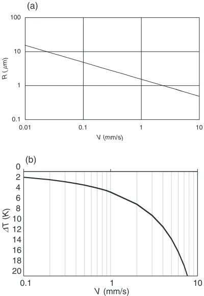
We do not yet have a complete picture of the exact processes leading to this breakup, but it is clear that a coarsening mechanism must play a key role. The dendrite arms that first form under conditions of rapid cooling possess a very high surface to volume ratio. For example, in Al–4.5% Cu alloy, dendrite tip radius is about 1mmfor a dendrite tip velocity of 1 mm/s, or for growth of a free dendrite in the alloy at 4 K undercooling, Fig. 11.25,26) The qualitative
picture we have is that arms separate from these dendrites as a result of material transfer from dendrite arm roots to regions of lower curvature, with the transfer enhanced by thermal fluctuations from the convection. The convection also serves to eliminate any remaining superheat in the bulk liquid, and to carry dendrite fragments from the cooling surface throughout the casting or ingot.
0.1 1 10 100
0.01 0.1 1 10
V (mm/s)
R ( m)
(a)
µ
0 2 4 6 8 10 12 14 16 18 20
0.1 1 10
V (mm/s)
∆
T (K)
[image:4.595.327.527.456.746.2](b)
Fig. 11 Relationship between a) dendrite tip radius,r, and tip velocity,V, and b) tip undercooling,T, and tip velocity, for Al–4.5 mass%Cu (from Flemings,25)based on growth model of Kurz and Fisher.26)
0 400 800 1200 1600
0.3 0.5 0.7 0.9
Solid fraction
Cubic coarsening coefficient, K
[image:4.595.62.276.607.748.2]Whatever may be the details of the mechanism, it is clear that vigorous agitation, combined with rapid heat extraction in just the earliest stages of solidification, is the key to obtaining a fine grain structure. Two particularly effective methods for doing this are 1) pouring liquid alloy down a ‘‘cooling slope,27)’’ and 2) rapidly stirring the alloy with a
cold ‘‘heat extractor.16,28)’’ If the ‘‘nuclei’’ from the
fragmen-tation process are sufficient in number, growth of grains is spheroidal and the minimum possible grain size is achiev-ed—which is that dictated by ripening during solidification. Figure 12 shows schematically the second of these two methods, from doctoral thesis work of Raul Martinez.15,16)A cooling rod is immersed briefly into a liquid metal bath- long enough to cool the bath to just below the liquidus. After only a very small fraction solid forms, the stirring rod is removed and the semi-solid metal allowed to cool quiescently.
Figure 13 shows the spheroidal growth structures that result in Al–4.5% Cu alloy solidified in this manner. The structures are from melts cooled quickly through the liquidus with vigorous stirring, then slowly cooled and and quenched after 6 and 80 s respectively. The average diameters of the grains are 20 and 50mmrespectively. These, and similar data points for other times, fall on the upper bound of the scatter band of Fig. 9, as shown by the square points in that figure. From measured temperatures and by application of the Scheil equation, fractions solid are estimated to have been 0.05 and 0.30 respectively at the time of quench. The number of grains growing was about1104grains/mm3 after 5 seconds, and
4103grains/mm3after 60 seconds. It is not possible from
this experiment to determine whether, in times shorter than about 5 s, growth was dendritic, although no remnant of a ripened dendritic structure was apparent in the microstructure of the sample quenched at 5 s.
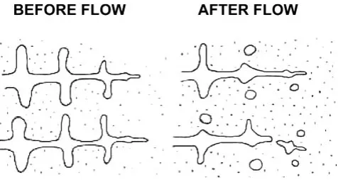
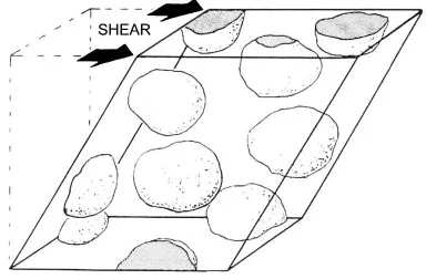
It should perhaps be added here that industrial interest in obtaining these fine spheroidal structures is both to achieve improved properties of the final cast structure and to obtain readily flowable material for semi-solid forming, Fig. 13. Much has now been written of the relation of structure to semi-solid formability, and it is clear that coarsening plays an important role in determining the thixotropic behavior of semi-solid alloys, even when the desired fully spheroidal structure is present, Fig. 14.29,30)
6. Some Unanswered Questions
There remain many unanswered questions concerning coarsening in solidification, particularly with regard to short times and/or fine structures, which are the regimes most difficult to study experimentally. At least some of these questions are answerable today, however, with newer sensing and measuring instruments, or with transparent materials. Here, to conclude this talk, are three such questions. Each has important engineering implications:
[image:5.595.305.549.72.162.2]What determines grain size in non-grain refined melts? The evidence is strong that many grains in non-grain refined melts result from dendrite multiplication. We can surmise, but do not know, the detailed mechanism of the dendrite breakup. We do not know what fraction of the grains result from a classical nucleation event and what fraction from the dendrite breakup. Of course, the experimental problems are formidable. Assuming the same dendrite coarsening kinetics observed at large spacings extend to the very fine initial structure of, say, a dendrite arm spacing of 2mm, then every
Fig. 12 Three basic steps of efficient dendrite multiplication: combining vigorous convection with a region of localized rapid cooling during the early stages of solidification.16)
[image:5.595.53.281.72.379.2]Fig. 13 Spheroidal growth of Al–4.5 mass%Cu alloy, stirred while cooled through the liquidus and then quenched after (a) 6 s and (b) 80 s.
[image:5.595.329.521.215.341.2]third dendrite arm would disappear in times on the order of 0.01 s.
How do coarsening phenomena influence structure of inclusions? We have limited evidence that the coarsening mechanisms discussed for the major solidifying phase influence the size and morphology of non-metallic inclu-sions. Figure 15 shows some possibilities schematically. Few closely controlled studies have been carried out on this aspect of solidification.
What are the essential elements of a good grain refiner? The ‘‘fading’’ phenomena of most grain refiners strongly suggest an important role of coarsening in addition to sedimentation. It is not clear how such coarsening might affect the number, and morphology of heterogeneous nucleating particles and thereby the role they play in nucleation. It seems possible, for example, that the number of nucleating particles can be increased by ‘‘nucleant multiplication’’, as well as decreased by coalescence, as sketched in Fig. 15.
Acknowledgements
The author is grateful for the careful reading of the manuscript by Profs. D. R. Poirier and T. Koseki, and for much appreciated contributions of Dr. R. Martinez and Mr. P. Sung.
REFERENCES
1) S.-C. Huang and M. E. Glicksman: Acta Metall.29(1981) 717. 2) S. P. Marsh and M. E. Glicksman: Metal. Mater. Trans.27A(1996)
557.
3) R. Mendoza, J. Alkemper and P. W. Voorhees: Metal. Mater. Trans.
34A(2003) 481.
4) M. E. Glicksman, M. B. Koss and E. A. Winsa: Phys. Rev. Lett.73
(1993) 573.
5) T. Z. Kattamis, J. C. Coughlin and M. C. Flemings: Metall. Trans.239
(1967) 1504.
6) T. F. Bower, H. D. Brody and M. C. Flemings: Metall. Trans.236
(1966) 624.
7) B. P. Bardes and M. C. Flemings: Trans. AFS66(1974) 406. 8) S. Annavarapu and R. D. Doherty: Acta Metall. Mater.43(1995) 3207. 9) R. E. Spear and G. R. Gardner: Trans. AFS71(1963) 209.
10) D. R. Poirier, S. Ganesan, M. Andrews and P. Ocansey: Mater. Sci. Eng. A148(1991) 289.
11) D. H. Kirkwood: Mater. Sci. Eng.65(1984) 101.
12) M. Chen and T. Z. Kattamis: Mater. Sci. Eng. A247(1988) 239. 13) A. Mortensen: Metall. Trans.20A(1989) 247.
14) V. R. Voller: J. Cryst. Growth197(1999) 333.
15) R. A. Martinez: PhD Thesis, MIT Department of Materials Science and Engineering, MIT (2004).
16) R. A. Martinez and M. C. Flemings: Mater. Trans. A (submitted). 17) G. W. Greenwood: Acta Metall.4(1956) 253.
18) I. M. Lifshits and V. V. Slyozov: Phys. Chem. Solids.19(1961) 35. 19) C. V. Wagner: Electrochemis,65(1961) 581.
20) P. W. Voorhees and M. E. Glicksman: Metall. Trans. A15(1984) 1081. 21) E. D. Manson-Whitton, I. C. Stone, J. R. Jones, P. S. Grant and
B. Cantor: Acta Mater.50(2002) 2517.
22) M. E. Glicksman, R. N. Smith, S. P. Marsh and R. Kuklinsky: Metall Trans.23A(1992) 659.
23) E. F. Emley:Principles of Magnesium Technology, (Pergamon Press, Oxford, New York, 1966).
24) M. C, Flemings:Solidification Processing, (John Wiley, New York, 1974).
25) M. C. Flemings: in Solidification Processes and Microstructures, (TMS, Warrendale PA, 2004).
26) W. Kurz and D. J. Fisher:Fundamentals of Solidification, (Trans Tech Pub, Aamensdorf Switzerland, 1985).
27) T. Haga and S. Suzuki: Proc. of the 6th Int. Conf. on the Proc. of Semi-Solid Alloys and Composites, Brescia, Italy (2000) 221.
28) M. C. Flemings, J. A. Yurko and R. A. Martinez: Proc. of the 8th Int. Conf. on the Proc. of Semi-Solid Alloys and Composites, Cyprus (2004), Paper # 02-01.
29) M. C. Flemings: Metall. Trans.22A(1991) 957.
30) J. A. Yurko and M. C. Flemings: Metall. Trans.33A(2002) 2737. 31) M. C. Flemings: Int’l Met Rev.220(1977) 187.
. Received his S. B. degree from MIT in Department of Metallurgy in 1951, and his S.M. and Sc. D. degrees in Metallurgy, also from MIT, in 1952 and 1954, respectively. Worked as Metallurgist at Abex Corporation, NJ, from 1954 to 1956, and returned to MIT as Assistant Professor in 1956. Associate Professor in 1961, Professor in 1969 and Professor Emeritus in 2002. First director of Materials Processing Center at MIT in 1979, Head of Department of Materials Science and Engineering from 1982 to 1995, Director of MIT Center for the Singapore-MIT Alliance from 1998 to 2002, and currently Director of Lemelson-MIT Program. Elected to Honorary Member of The Japan Institute of Metals in 1995.
[image:6.595.51.290.69.228.2]. Solidification science and engineering, foundry technology, and materials processing.