warwick.ac.uk/lib-publications
Permanent WRAP URL:
http://wrap.warwick.ac.uk/108039/
Copyright and reuse:
This thesis is made available online and is protected by original copyright.
Please scroll down to view the document itself.
Please refer to the repository record for this item for information to help you to cite it.
Our policy information is available from the repository home page.
PHOTOELECTRON DIFFRACTION CALCULATIONS FOR ADSORBATE SYSTEMS
by
Malcolm Steven Woolfson, 3.Sc.
A thesis submitted for the degree of Doctor of Philosophy, University of Warwick,
Department of Physics
The aim of this work is to assess the potential usefulness of photoelectron diffraction in the determination of surface structure. A review is first made of the theory of photoelectron diffraction from crystalline surfaces. Then, calculations of the variation of intensity with azimuthal angle are performed for various model systems, in order to investigate the sensitivity of the diffraction patterns to structural and non-structural parameters. It is found that for detector angles lying approximately half-way between the surface and surface normal, and for some photon energies, the diffrac tion patterns are sensitive to structure. For some energies, the patterns sure found to be sensitive to non-structural parameters, making it necessary to know these parameters to a high precision. Then, am analysis is made dr data taken in the azimuthal mode for 4d emission from cC2 x 2) and p(2 x 2)Te adsorbed on Ni(OOl) and for 4d emission from
(VJ
x/J)
R30°I adsorbed on AgClll). By transfering parameters from the relevant LEED calculation quite good agreement between theory and experiment is obtained for I on Agllll) but the agreement is poor for both coverages of Te on Ni (001). Subsequently the case of normal emissioncross-2 ?
sections for atomic Xe, Kr and Ar using the Slater, Hara and Lee and Beni potentials, and a comparison is made with experiment gas phase data. Hara exchange is found to be superior to the Lee and Beni potential especially at low energies. It is suggested that the in adequacy of the Lee and Beni potential is due to a breakdown of the Local Density Approximation and the success of the Hara potential is due to a cancellation of errors. Angle-resolved photoemission from adsorbed molecules is then looked at in order to assess the importance of multiple scattering. It is found that near to a resonance it is essential to incorporate multiple scattering. It is found that the Mattheis prescription of superposing atomic charge densities is inadequate in describing the emission and scattering properties of molecules, and it is preferable to use the Scattered-Wave Xa method which more realistically describes the distribution of charge within the molecule.
List of Figures 6
Acknowledgements- 13
Memorandum 14
Abstract
CHAPTER 1: INTRODUCTION 16
Reference for Chapter 1 23
CHAPTER 2: THEORY OF ANGLE-RESOLVE6 PHOTOEMISSION FROM
THE CORE STATES OF ADSORBATES 25
2.1. The Model Surface 25
2.2. Theory of Photoemission from an Atomic Orbital 26 2.3. Emission from a Crystal Surface 31
2.3.1. The General Multiple Scattering Series 32
2.3.2. The Unscattered Term 34
2.3.3. Single-Scattering Terms 35
2.3.4. The Multiple Scattering Series for a Crystal 35 2.3.5. Computation of the Multiple Scattering Series 37
2.4. Calculation of the Atomic Potential 39 2.4.1. Calculation of the Coulombic Potential V (r) 40
c
2.4.2. Calculation of the Exchange Potential V^tr) 41 2.4.3. Calculation of the Ionic Contribution (r) 43 2.4.4. Calculation of the Constant Potential between
muffin-tins. 44
2.4.5. Practical Considerations 44
References for Chapter 2 46
CHAPTER 3: THE SENSITIVITY OF AZIMUTHAL PHOTOELECTRON DIFFRACTION 48 PATTERNS TO STRUCTURAL AND NON-STRUCTURAL PARAMeTÉRS
4
3.2. Sensitivity to Structural Parameters 43
3.3. Sensitivity to Non-Structural Parameters 54
3.4. Conclusions 55
References for Chapter 3 57
CHAPTER 4: CORE STATE EMISSION: COMPARISON BETWEEN THEORY AND
EXPERIMENT. 55
4.1. Introduction 58
4.2. Review of Past Work 58
4.3. Analysis of Data for Ion Ag(lll) and Te on
Ni (OOl) . 61
4.3.1. AgClll) - t/3 x /3)R30°I 61
4.3.1.1. Analysis of the Data for the In-Plane
Configuration. 62
4.3.1.2. Analysis of the Data taken with the
Out-of Plane Configuration 66
4 .3.1.3. Discussion 67
4.3.2. N i (001) - c (2 x 2)Te and N i (001) - p(2 x 2)Te 68
4 .4 . Summary 71
References for Chapter 4 72
CHAPTER 5: CHOICE OF MODEL POTENTIAL FOR PHOTOELECTRON DIFFRACTION 74
5.1. Introduction 74
5.2. The Calculation of the Atomic Potential 74 5.3. Normal Emission from the 4d levels of c(2 x 2)Te
adsorbed on N i (001). 80
5.4. Ni (OOl) - c (2 x 2)Te and Ni(OOl) - p(2 x 2)Te: A Second Analysis of the Data Taken with the
Azimuthal Mode. 82
5.5. The Lee and Beni Potential 83
PAGE
3.2. Sensitivity to Structural Parameters 43
3.3. Sensitivity to Non-Structural Parameters 54
3.4. Conclusions 88
References for Chapter 3 57
CHAPTER 4: CORE STATE EMISSION: COMPARISON BETWEEN THEORY AND
EXPERIMENT. 58
4.1. Introduction 58
4.2. Review of Past Work 88
4.3. Analysis of Data for Ion Ag(lll) and Te on
Ni (001) . 61
4.3.1. Ag(111) - l/3 x /3)R30°I 61
4.3.1.1. Analysis of the Data for the In-Plane
Configuration. 62
4.3.1.2. Analysis of the Data taken with the
Out-of Plane Configuration 66
4.3.1.3. Discussion 67
4.3.2. N i (001) - c (2 x 2)Te and N i (001) - p(2 x 2)Te 68
4.4. Summary 71
References for Chapter 4 72
CHAPTER 5: CHOICE OF MODEL POTENTIAL FOR PHOTOELECTRON DIFFRACTION 74
5.1. Introduction 74
5.2. The Calculation of the Atomic Potential 74 5.3. Normal Emission from the 4d levels of c(2 x 2)Te
adsorbed on N i (001). 80
5.4. N i (001) - c (2 x 2)Te and Ni(001) - p(2 x 2)Te: A Second Analysis of the Data Taken with the
Azimuthal Mode. 82
5.5. The Lee and Beni Potential 83
PAGE
5
5.S.2. Lee and Beni Potentials for Atomic Xe, Kr
and A r . 87
5.6. Discussion 89
References for Chapter 5 92
CHAPTER 6: ANGLE-RESOLVED PHOTOEMISSION FROM ADSORBED MOLECULES 94
6.1. Introduction 94
6.2. Theory gg
6.3. Comparison Between Theory and Experiment for
Various Molecular Adsorbate Systems. -jqi
6.3.1. CO adsorbed on Ni 101
6.3.1.1. Calculations for oriented CO 101 6.3.1.2. Calculations for CO adsorbed on N'i(OOl) 104
and Ni (111) .
6.3.2. C 2H4 on NiCOOl) andNi(lll). 108
6.3.3. C2H4 on NiCOOl). n o
6.4. Summary 112
References for Chapter 6 m
CHAPTER 7: CONCLUSIONS 116
References for Chapter 7 12 1
APPENDIX Is Evaluation of <e£'m' | e.p|nim> 122
Reference for Appendix 1. 124
APPENDIX 2: Expansion of hj (K|r-e |) (r-e) in plane waves. 125
Reference for Appendix 2. 127
Figure Number
2
.
1.
3.1. 3.2. 3.3. 3.4. 3.5. 3.6.
LIST OF FIGURES
Title
Cross-section and profile of the muffin-tin potential.
Comparison between theory and experiment for the azimuthal depen dence of photoemission from the Na 2p levels for NiCOOl) - cC2 x 2)Na.
Calculations for the azimuthal variation of photoelectron intensity for Na 2p emission from NiCOOl) - c(2 x 2)Na at 30° to outward surface normal for photon energy 90 eV.
Opposite Page Number___
25
50
51
As for fig. C3.2) except that now the
detector angle is 80°. 52
Calculations for the azimuthal variation of photoelectron intensity for Na 2p emission from NiCOOl) - c (2 x 2)Na and Se 3d emission from NiCOOl) - c(2 x 2)Se
varying the number of layers. 5 3
Calculations for the azimuthal variation of photoelectron intensity for Te 4d emission from NiCOOl) - cC2 x 2)Te, varying the detector angle by 2°.
Calculations for the azimuthal variation of photoelectron intensity for Te 4d emission from NiCOOl) - c (2 x 2)Te varying the angle
3.7. Figure Number 4.1. 4.2. 4.3. 4.4. 4.5. 4.6. 4.7. 4.8.
Title Opposite Page
Number
Calculations for the azimuthal variation of photoelectron intensity for Te 4d emission from N i (001) - c(2 x 2)Te, varying the elec
tron kinetic energy by small amounts. 55 Comparison between experimental data and
calculations of Kdng et al for I 4d emission
from Ag(lll) - (/? x /3)R30°I. 62
Effect of varying a on the calculated photo electron diffraction curves for X 4d emission from Ag(111) - (/3 x <^31R30°I, for electron
kinetic energy 45 eV. 64
Comparison between theory and experiment for
X 4d emission from Ag(lll) - (»'T x /J)R30°1. 64 Effect of varying the bonding site for electron
kinetic energies 35 eV, 45 eV, and 55 eV. 64 Effect of varying d^ for electron kinetic
energies 35 eV, 45 eV and 55 eV. 65 Experimental data for the (jx]) phase of I
adsorbed on Ag(lll), compared with the calculations of King et al.
Comparisons between theory and experiment for the data taken with the detector and light source in perpendicular planes.
Comparison between theory and experiment for Te 4d emission from c (2 x 2)Te and p(2 x 2)Te
65
66
Figure Title
Number
---Opposite Page Number
4.9. Photoelectron diffraction calculations for Te 4d emission from Ni(001) - c (2 x 2) Te, where the ¿ ^ s p a c i n g is varied by ± O.lX
from its LEED value. 69
4.10. Effect of changing the detector angle 9 by ± 2° from its nominal value of 30° with respect
to the surface normal. 70
4.11. Effects of changing the bonding site on the
photoelectron diffraction curves. 70
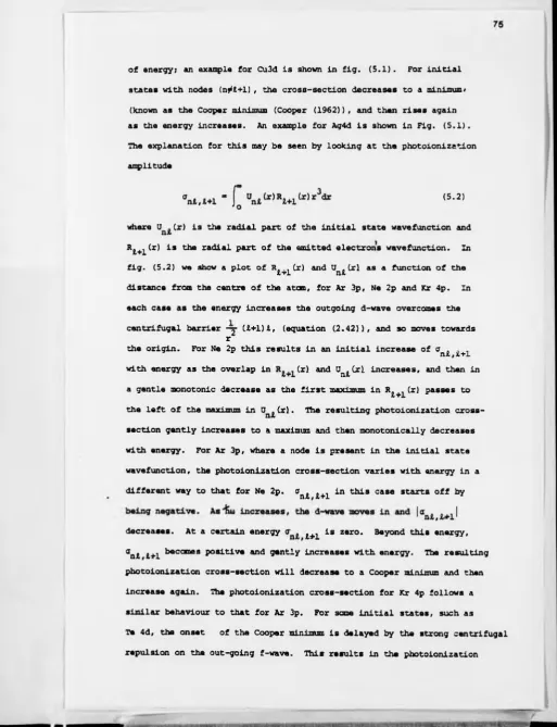
5.1. Photoionization cross-sections for Cu 3d and
Ag 4d. 75
5.2. Plot of U . Cr) and R . ,,(r) versus r for Ne 2p,
n l l+l
Ar 3p and Kr 4p. 75
5.3. Hie photoionization cross-section for Xe 4d versus photoelectron energy: Comparison between calculations using Hartree-FocJc and ground state Xa potentials. Also presented
is the experimental data. 76
5.4. Phase shifts for Xe in crystalline form versus electron kinetic energy in the vacuum: comparison between Hartree-Fock and Xa (a=l).
calculations. 75
5.5. As for fig. (5.4) except that now a has been
reduced to 0.5 in the Xa calculation. 77
5.6. Photoionization cross-section for Xe 4d versus electron kinetic energy varying a in the Xa
9
5.7. 5.8. 5.9. Figure Number 5.10. 5.11. 5.12. 5.13.As for fig. (5.6) except that now calculations are for Te 4d.
Photoionization cross-section versus electron kinetic energy for Xe 4d using Hara exchange potential premultiplied by an a parameter.
Photoelectron diffraction data for normal emission from the 4d levels of c(2 x 2)Te adsorbed on Ni(001) compared with calcula tions using a ground state Xa potential for Te.
Comparison between the data and calculations presented in fig. (5.9) along with a calcula tion using the Hara potential for Te with a = 0.5.
Calculations for the azimuthal distribution of photoelectron intensity for emission from the 4d levels of p(2 x2)Te and c (2 x 2)Te adsorbed on Ni(001) using the Hara potential for Te with a « 0.5.
Comparison between different calculations for the back-scattering amplitude for atomic Br.
Experimental data for the total cross-section of atomic Ar, Kr and Xe versus electron kinetic energy, along with calculations using different
Title Opposite Page
Number 78 79 80 80 82 87
Number Title Number
5.14.
6
.
1.
6
.
2.
6.3.
6.4.
6.5.
6
.
6.
Differential cross-section for elastic scattering from Ar, Kr and Xe at various electron energies versus scattering angle.
Photoemission spectra for CO adsorbed on various transition metal surfaces compared with spectra for Ir4 (CO) 12 and for gas phase CO.
Comparison between SW-Xa calculations and experimental data for normal emission from the 4a level of C O adsorbed on Ni(OOl) . The angle-resolved photoemission intensity from the 4a,lrr and 5a levels of oriented CO: comparison between calculations that include intra-molecular scattering and those leaving out this effect.
The angle-resolved photoemission intensity for emission from the 4a level of oriented CO for hu = 40 e V and 60 eV: Comparison between calculations that neglect multiple scattering, calculations that include intra molecular scattering and experimental data. Angle-resolved photoemission from the 4a level of CO adsorbed on N i (001) for hu = 28 eV: Comparison between experiment and SW-Xa calculations.
Calculations that neglect scattering for the data presented in fig. (6.5).
11
Figure
Number Title
Opposite Page Number
6.7.
6
.
8.
6.9.
6
.
10.
6
.
11.
6
.
12.
6.13.
Energy dependence of the normal emission from the 4a level of c(2 x 2)CO adsorbed on N i (001): Comparison between experiment calculation that includes full multiple scattering using the SW-Xa potential for CO and calculations incorporating full multiple scattering superposing atomic C and 0 potentials.
Calculations for the data presented in fig. (6.4) that include full multiple scattering and using the CO potential constructed from atomic C and 0 potentials.
Calculations for the data presented in fig. (6.5) that include full multiple scattering and using the CO potential employed in the calculation in fig. (6.8).
Electron distribution curves for N i (001) - c(2 x 2)C2H2 as a function of photon incidence angle.
Electron distribution curves for N i (001) - c(2 x 2)C2Hj as a function of photon incidence angle.
Calculations that neglect scattering for the data presented in fig. (6.1 0).
Calculations neglecting scattering for the angle-resolved intensity from 2o and 3c levels of
u g
Figure
Number Title
Opposite ] Number
6.14. Calculations neglecting scattering for
the data presented in fig. (6.1 1). 1 1 1 6.15. Calculations neglecting scattering for
the variation of intensity with detector
13
ACKNOWLEDGEMENTS
I am grateful to my supervisor Dr. B. W. Holland for his encourage ment and help during the course of this work and for patiently checking my thesis prior to typing.
I would like to thank Professors A. J. Forty and P. N. Butcher for providing me with facilities to carry out research within the Department of Physics.
Thanks cure also due
to:-Drs. D. P. Woodruff and P. D. Johnson - for valuable discussions, for carrying out some of the calculations that are presented in this thesis and for providing me with, data prior to publication.
Drs. A. D. Cox and J. Mclnnes - for their help in computer graphics. Dr. H. Farrell - for providing me with data prior to publication.
Sandra Callanan - for her quick and efficient typing of this thesis and for decyphering my scrawl.
I have also benefitted from discussions with Drs. R. F. Pettifer and G. J. R. Jones.
I gratefully acknowledge the Science Research Council for supporting me financially during the course of this work.
All the work in this thesis is my own except where stated otherwise, and was carried out in the Department of Physics at the University of Warwick from October 1978 to September 1981.
Parts of this work have already been published as papers with the following references.
Phys. Rev. B21, 3119 (1980).. Solid State Conan., 35, 225 (1980) Solid State Comm., 3£, 961 (1981)
CHAPTER 1 INTRODUCTION
A fundamental quantity of interest in solid state physics is the structure of a crystal. Knowing the structure one can then proceed to calculate the electronic, magnetic and vibrational properties of the crystal. For over half a century the structures of many complicated crystals of industrial and medical importance have been determined by the technique of X-ray diffraction. However, due to the penetrating power of the X-rays this technique can only give information about the
structure of the bulk of the crystal and it can give no information about the arrangement of the surface atoms.
Many important processes, such as catalysis and corrosion, occur at the surface of a solid. To study such phenomena in detail there is a need to know about the nature of the bonding between the surface atoms and the adsorbed atom or molecule. This requires a knowledge of the position of the adsorbate with respect to the substrate atoms. Another problem of interest is the reconstruction of the atoms at the surface of a metal or semiconductor to form a structure differing from that in the bulk. This problem is clearly of importance in the electronics industry.
in order to determine the bonding site and vertical spacing (d^) of an adsorbed atom or molecule one has to study the variation of the intensity of the elastically scattered electrons with energy or angle. A detailed analysis of such data is difficult, because it is now known that or.a needs to consider multiple scattering of tha incident electrons by the surface atoms, (see e.g. Beeby (1968)). This technique is known as Low Energy Electron Diffraction (LEED). In TEED, because of the importance of multiple scattering effects, one has to postulate the structure first and then see whether the calculated intensity (I) versus energy (V) curves agree with experiment. Thus one may have to postulate a considerable number of structures before one can obtain agreement between theory and experiment. Consequently, it is only possible to study simple surface systems such as clean surfaces and surfaces with adsorbed atoms or small molecules. The effort in cal culating LEED curves is considerable but a lot of work has been carried out into formulating perturbative methods (see e.g. Pen dry (1974) , Van Hove and Tong (1979)), and with, the ever increasing power of computers it has became fairly straightforward to perform such calculations.
Although LEED has been successful in solving over a hundred structures, it has still come up against difficulties when investigating systems such as H on Ni where the scattering power of the adsorbate (Hi is far weaker
them that of the substrate (Nil. In this case the positions and relative intensities of the peaks in the IJV curves can be very insensitive to the position of the adsorbate atom and an accurate determination of d^ and the bonding site is difficult.
scattered electrons.that have been emitted from an adsorbate. This new method is very similar to LEED except that now the "source" of the electrons is the adsorbate whose position we are trying to find. Hence, in theory, the resulting diffraction curves should be more sensitive than LEED to the position of the adsorbate with respect to the substrate atoms. Theories of electron emission from crystalline surfaces that use a LEED-type of formalism to incorporate multiple scattering effects have been formulated in several different ways,
(Pendry (1975, 1976), Holland (1975), Liebsch (1976), Li et al (1977)), and it is clear that one may perform such calculations by only making small modifications to existing LEED computer programs. Electrons may be emitted from adsorbates by either Auger or photoemission processes. The latter method is preferred for surface structure analysis because in Auger emission, several initial states can contribute to a particular final state thus making such a calculation very involved. Cne requires the energy of the emitted electron to be in the energy range 30 eV to 200 eV in order to minimise the electron mean free path and so maximise the surface sensitivity of the diffraction patterns. It is thus desirable to use a synchrotron in these studies so that one may vary the photoelectron kinetic energy in this energy range. This new surface technique has come to be known as photoelectron diffraction.
19
from the details of the initial state will then be minimised. This method should then maximise the sensitivity of the diffraction pattern to structure. Also if data is taken for the full 360° rotation of the crystal then the symmetry in the data should be the same as the symmetry of the surface Bravais net. This then provides a check on the reliability of the data. We shall refer to this mode of data collection as the azimuthal mode.
A second method that has been employed is to look at the emission from a particular initial state, (again usually a core state), keep the detector and light source fixed with respect to each other and then vary the photon energy (fii)) and the retarding voltage in the detector so that one measures the intensity (I) of electrons emitted from this state as a function of Usually electrons emitted normal to the surface are monitored. The X:$iu curves so produced are similar in nature to LEED I :V curves. The disadvantage of using this mode of data collection is that for emission from initial states specified by quantum numbers n and l where n j* l + 1, the photoelectron diffraction curve is dominated by effects that are purely atomic in nature (Cooper (196211 and the effects of scattering result in minor perturbations on the experimental curve, (Xd and Tong (1979)1, thus reducing the sensitivity to structure. However, for initial states where n = l * 1 the atomic photoionization cross-section is a smooth function of energy, (Cooper
(19621), and the photoelectron diffraction curves are then dominated by multiple scattering effects. This mode of data collection is referred to as the Constant Initial State (CXS1 mode.
the data is known to be mainly dominated by the symmetry of the initial state with respect to the surface and this has been used to determine the orientation of small molecules adsorbed on various metal surfaces,
(see e.g. Williams (19Î0)).
Photoelectron diffraction experiments using both the azimuthal and CIS modes have been performed on various atomic adsorbate systems that have already been "solved" by LEED. The main aim has been to see whether by using the same structural and non-structural parameters as LEED in the photoelectron diffraction calculation one can obtain agreement between theory and experiment. This has successfully been done using the CIS mode for the surface systems Ni (0011 - cC2 x 2)Se and Ni (POIL - PC2 x 2)Se
(Kevan et al (1978, 1979), U and Tong (19791, Kevan et al (19811), Ni (001) - c (2 x 2)Na (Williams et al 0.979), Li and Tong (19791), and N i (001) - c(2 x 2)CO (Allyn et al (19771, Li and Tong (1978)1 and,using the azimuthal mode, for N i (001) - c (2 x 2)Na (Woodruff et al (1978)1, CuCOOl) and Cu(001) - c(2 x 2)0 (Xono et al (1978a, 1978bl, Ni (001) - d(2 x 2)CO, (Petersson et al (197911, and TaSj (Xiebsch (1976bl.
Experiments using the third mode of data collection have been mainly carried out on molecular adsorbate systems where the aim has been to determine the symmetry of the valence levels of the molecule with respect to the surface and so deduce the orientation of the molecule. The substrate is assumed to merely orient the molecule and the wavefunctions for the various molecular orbitals are approximated by those for the free molecule and the effects of scattering are usually neglected.
21
For CO the effects of substrate scattering and scattering between molecules have not been included in the calculations.
The aim of this work is to further assess the capability of photoelectron diffraction to determine surface structure. We shall look at data taken from atomic and molecular adsorbate systems. In Chapter 2 of this thesis we will outline the formulation of Holland (1975, 1977) of the theory of diffraction effects for photoemission from crystalline surfaces. We shall also describe the method that is adopted in the construction of the atomic potentials that are used in the description of the emission and scattering processes. Chapters 3 and 4 will be concerned with work on core-state emission from adsorbate atoms where the azimuthal mode has been used to collect the data. In Chapter 3 we will first present model calculations for various adsorbate systems, the aim being to decide on the experimental configuration that will result in us obtaining optimum sensitivity to structure. Then, we will proceed to look at the sensitivity of the diffraction patterns to small changes in the detector angle, and the energy and angle of incidence of the radiation. If the diffraction patterns are sensitive to these non-structural parameters then this means that these parameters need to be known very accurately. Sensitivity to these parameters could also degrade the structural sensitivity of the diffraction patterns. Chapter 4
will deal with comparisons between theory and experiment for the
adsorbate systems Ni (.001) - c(.2 x 21 Te, NiCOOll - p(2 x 21 Te and AgCllll-C/3 x /TlR30°I which have already been studied by LEED, and, for O T x /T)
o
R30 I on Ag(lll), also by Surface Extended X-ray Absorption Fine Structure CSEXAFS). We shall be interested in seeing whether we can transfer
/
REFERENCES FOR CHAPTER 1
Allyn, C. L., Gustafsson, T. and Plummer, E. W . , Chem. Phys. Lett. 47 , 127 (1977).
Banay, B. J., Lloyd, D. R . , and Richardson, N. V., Surf. Sci. 89, 344 (1979).
Beeby, J. L . , J. Phys. Cl, 82 (1968). Cooper, J. W., Phys. Rev. 128, 682 (1962).
Davenport, J. W . , Phys. Rev. Lett. 36, 945 (1976).
Davisson, C. J. and Germer, L. H . , Phys. Rev. 30, 70S, (1927). Holland, B. W., J. Phys. C8, 2679 (1975).
Holland, B. W., Surf. Sci. 6 8, 490 (1977).
Kevan, S. D., Rosenblatt, D. H . , Denley, D . , Lu B-C., and Shirley, D. A., Phys. Rev. Lett. 41, 1565 (1978).
Kevan, S. D., Rosenblatt, D. H., Denley, D . , Lu, B-C., and Shirley, D. A., Phys. Rev. B 2 0 , 4133 (1979).
Kevan, S. D. , Tobin, J. G . , Rosenblatt, D. H . , Davis, R . , and Shirley, D. A., Phys. Rev. B 2 3 , 493 (1981).
Kono, S., Fadley, C. S., Hall, N. F. T. and Hussain, Z. , Phys. Rev. Lett. 41_, 117 (1978a).
Kono, S., Goldberg, S. M . , Hall, N. F. T., and Fadley, C. S., Phys. Rev. Lett. 41_, 1831, (1978b).
Li, C. H. , Lubinsky,, A.. R. and Tong, S. Y . , Phys . Rev. B 1 7 ,, 3128 (1977) •
Liebsch, A . , Phys. Rev. Lett. 32^, 1203 (1974). Liebsch, A., Phys. Rev. B 1 3 , 544 (1976a)
Liebsch, A., Solid Stat Comm., 19_, 1193 (1976b).
Lloyd, D. R . , Quinn, C. M. and Richardson, N. V., Surf. Sci. 68_, 547 (1977). McGovern, Z. T . , Eberhardt, W. and Plummer, E. W . , Solid State Comm. 32_,
963 (1979).
Pendry, J. B . , Low Energy Electron Diffraction, (Academic Press, London 1974). Pendry, J. B., J. Phys. C8, 2413 (1975).
Pendry, J. B . , Surf. Sci. 5 7 , 679 (1976).;
Petersson, L-G., Kono, S. , Hall, N. F. T . , Fadley, C. S., and Pendry, J. B . , Phys. Rev. Lett. 4 2 , 1545 (1979).
Umbach, E . , Schuhl, A. and Manzel, D . , Solid State Comm. 36_, 93 (1980). Van Hove, M. A., and Tong, S. Y., Surface Crystallography by LEED, (Springer
-Verlag, Berlin, 1979).
Williams, R. H . , Rep. Prog. Phys. 43, 1357 (1980).
Williams, G. P . , Cerrina, F . , McGovern, I. T. and Lapeyre, G. J . , Solid Stat Comm. 31, 15 (1979).
Woodruff, D. P., Surf. Sci. 5 3 , 538 (19751.
25
CHAPTER 2
THEORY OF ANGLE-RESOLVED PHOTOEMISSION FRQM THE CORE STATES OF ADSORBATES
2.1. The Model Surface
The calculation of the angle-resolved intensity of electrons emitted from the core-state of an adsorbate may be separated into two parts:
(i) the calculation of the wave-function of the electron emitted from the atomic orbital and (ii) the calculation of the perturbation of this wavefunction due to multiple scattering of the electron by atoms in the adlayer and substrate. The ion-core potentials within the crystal are modelled by the muffin-tin approximation, (Loucks (1967)). In this approximation, the potential about each atom is assumed to be spherically symmetric up to a distance R^, from the centre of the atom. Outside this limit the potential is averaged out to a constant, (Fig. 2.1). The potentials of neighbouring atoms are assumed not to overlap. This approx imation is known to be a good one from IEED work on metals and insulators,
effects cure isotropic and uncorrelated. It may then be shown, (Duke and Laramore (1970), Laramore and Duke (1970), Holland (1971)), that such effects may be taken into account by making the atomic phase shifts complex. The polarization vector A will vary in a compli cated way with distance into the substrate, (Kliewer (1978), Feibelman
(1978), Mukhopadyay and Lindquist (1978)). However, for core state emission where, experimentally, photon energies well above the plasmon energy are used, it should be a good approximation to take A as having no spatial dependence. Many-body effects such as plasmon excitation and creation of electron-hole pairs are normally assumed to have a negligible effect on the angle resolved photoelectron intensity.
The derivation of the wavefunction for the emitted electron from an atomic orbital that we will describe below is due to Holland (1977). Alternative derivations exist, (see Feuerbacher and Willis (1976) for further references).
2.2. Theory of Photoermssion from an Atomic Orbital
The Hamiltonian for the atom and electromagnetic field is giyen by (see e.g. Dirac (1967)):
a ~ - t <* - ? ^ )2 + 71x1 + H rad C2.1)
A
where V(r) is the atomic potential, A is the vector potential operator and Hrad Is the Hamiltonian for the radiation. If it is assumed that A is independent of position so that [g, A] = 0, and that terms of order
« 2
(A) may be ignored then we may write:
where H o
H + H, rad
~r— + V(r) is the atomic Hamiltonian and
¿m
27
H
1 (2.3)
is the term representing the electron-photon interaction. We are only concerned with the effect of the perturbation on the unperturbed system so from now on we ignore Hra(j* Using the method of second quantiration, may be re-written as:
H
1 + a -qo (2.4)
where u is the photon frequency, a is a polarization index, ft is a normalization volume, q is a photon wavevector, is the polarization vector of the electromagnetic field and a and a^ are respectively
qa qa
the annihilation and creation operators for the photons with wavevector
q .
Let the unperturbed wavefunction for the system be |i>. Then we may write:
|i> = |p>|nlm>
where |nlm> is the initial state of the electron and |p> is the wave- function for the electromagnetic field. Let the perturbed wavefunction be |i+ >. Then |i+ > may be related to |i> by the Lippmann-Schwinger equation (see e.g. Roman (1965)):
|i+> |i> + lim
n-*o
+ e-h +in 1oH,li+ > (2.5)
where H|i+ > * E|i+ >, HQ |i> 3 E^|i> and n is a positive real number that prevents the Green operator (E-H +inl ^ becoming singular. In writing
o
down equation (2.5) it is assumed that both H and H have a continuum o
perturbation is slowly added on as t increases. A zeroth order solution to equation (2.5) is to put |i+> = |i>. Inserting this on the right hand side equation (2.5) and inserting the identity operator £|r><r| into the second term on the right-hand side |i+ > may be written to first order in the perturbation as:
<r | H. | i>
|i > - |i> + Urn l E_g |r> C2.6)
n-*o r
Cne now takes the scalar product of equation (2.6) with the null photon, (or electromagnetic vacuum state), |o>. On the right-hand side only those terms of the form |r> » |o>|ei'm'> survive where |eJt'm'> is an eigenfunction of the atomic Hamiltonian. For radiation in the ultra violet part of the electromagnetic spectrum, one may approximate
|q.r|<<1 in equation (2.4) so that exp(iq.r)3 1. Also it is assumed that initially there is one photon with wavevector q. Making all these assumptions the wavefunction for the emitted electron !nlm+> may be written as:
|nim+> - Y l l' rm'
fdep^,^,(e)<ei,m'|e.p|n£m>
| ei. 'm' > , (2.7)
where y - - — me
ffeef]
, and P^,m i(t) is the density of states for the emitted electron. Outside the muffin-tin, |ei'm'> may be written in the co-ordinate representation as
i 5 »- +
-lei'm' > = Yitjn, Cr) Ce h^(kr) + e h^-Ocr)] ,
where k 2me
j.2 and h^Ckr) and h^ (krl are respectively Hankel functions
29
be written in the co-ordinate representation as:
<r|n£m+> = (r-) ■ y
<€i'm'|e.p|niin>
l * » i V (i)e +-tiu~-’c + in
l m n
x Y ei6*'h +
-i6
»-(kr) + e h7* (kr) (2.8)
Integrating over e :
(r) » iiry 7 e L p.. „ (c +hu) <e Ie.p|niin>
- .t .. i m n n - »
l m
x
- 2 2
where — — =» e + hw is the kinetic energy of the outgoing electron. 2m n
This term represents a superposition of outgoing spherical waves centred on the emitting atom.
Converting to the co-ordinate representation let us write:
(2.9)
and
<r|nim> - UnJl(r)Yia(0,$)
<r|e +'H u,i'm '> » R,,.Crl Y „ . (9,$) ,
n -C A. IQwhere 9 and $ are respectively the polar and azimuthal angles of the emitted electron with respect to the inward surface normal.
Performing the angular integrations, it may be shown that: i5.
8 - C (21+1) (21+3) ] '
4
—id»0
-hL U+l+m) U+2-hn) ] a *
x 3in9' V i , a + i (9'*‘
+ «iCU+l-m) a +2-m)]l,ei* >
X 3in9' V l . m - 1 19'*1
ywftpa + ----r
1-K +
V 1
C (21+1) (2£-l) 3** (Kr)
*sC U-l-m) U-m) ^ e” 14
x 3in9' V l , m + l (0'*)
-hiU-m-D CA-Hn) ^ e14
x s i n e ' Y ^ ^ O , * )
+ (Z2-m2)‘5cose'Y. . (9 # $) | (2.10) Jt—l/in )
where (0■',$') are the angular coordinates of the A-vector. The quantity
9 is known as the photoionization amplitude for the orbital |nim> and it gives the probability that the emitted electron will have orbital quantum number l'. Equation (2.10) shows that the quantum numbers Cl',
31
n i,l'
rco
r i
1
v (r) dV (r)
fiu dr
o
U (r)r dr
ni (2.13)
For the muffin-tin approximation equation (2.13) will be most convenient to use, for then dV(r)/dr is zero outside R ^ , so that we only need to integrate out to R . Further details of the calculation of this qunatity will be presented in section (2.4).
If we consider emission from an atomic core-state |nim>, we would have to take account of the (21+1)-fold degeneracy of the corresponding energy level by incoherently summing the intensities from the orbitals
|nJM>, |nl,i-l>,..., |nl, -(¿-1)>, |ni,-i> to find the total intensity of the emitted electron. For emission from valence states, e.g. a bond between two atoms, one would first have to calculate the initial state as a linear combination of atomic orbitals (LCAO), (see e.g. Coulson
(1965)), in order to use the above formalism to calculate the emitted electron intensity. In the case of a bond between an adatom and the substrate such a calculation is difficult, (Grimley (1976)1.
2.3. ssion from a Crystal Surface
o
He now need to consider the perturbation of 41 (rl due to multiple scattering of the emitted electron off the ion cores in the surface region. It has been shown that multiple scattering can significantly effect the photoelectron diffraction pattern, (McDonnell et al (19751, Woodruff C1975) , Tong and Van Hove (19761, Liebsch (1976)). This problem has been extensively studied in the context of TEED, where the emphasis has been on the development of perturbation schemes that are both accurate and efficient to run on a computer, (see Van Hove and Tong (19791 for a review of perturbation methods in LEED).
(1976), Li et al (1977)). we will outline below the formulation of the multiple scattering series due to Holland (1975).
2.3.1. The General Multiple Scattering Series
The emitting atom is placed at position vector e_. The Hamiltonian for the emitted electron may be written as:
H » H' + V o where :
B' =■ - V2 + V
o 2m o
Vq is the constant complex potential mentioned earlier and V is the potential due to the ion cores which are modelled by the muffin tin approximation.
In LEED work, the real part of the complex potential is usually calculated by aligning theoretical peak positions with experiment in the IIV spectra. The imaginary part of V q , (related to the mean free path), is varied until the peak widths are reproduced by the theory. In general, the IJV curves are insensitive to Im(Vo ). Of course this procedure assumes that the complex potential is energy independent, but this is known to be a good approximation over the energy range of interest,
(see e.g. Pendry (1974)1. It is assumed that the complex potential that is used in the LEED calculation for a particular system may be transferred to the photoelectron diffraction calculation for this system. The electron wavevector in the crystal, K, will be complex and is given by:
K2 - % CE-Vl (2.141
where the convention has been used that R e 07 1<0 and Im(V 1<0.
o o
3 3
- (1 + GT)*fi (2.15)
where \|i = |nim> is the initial state, T is the T-matrix representing multiple scattering by the ion cores and G = (E-Hq ) T may be expanded in a multiple scattering series, (see e.g. Beeby U.968), Holland (1977)), and i(i then becomes:
* - (1 + G l i + G l ia G t#, + ' sirfe - s.s'
(s^s's'j^e)
.)♦. (2.16)
where t is the T-matrix for the ion core at s. y is given in the
-g * e
co-ordinate representation outside the muffin-tin radius by equation (2.10) and 1)»0 is related to by:
e
i|»° « (1 + G t»)*° e ** ~ *■© He rewrite equation (2.10) as:
* e (?"?> “ l btohi •
l ,m
In the co-ordinate representation (2.161 may be rewritten as:
(2.17)
rr
4*(r,e) » (r-e) +
" ** a - *• Gir-r") l t (r',r")t|i°(r"-e) d V d V ' s(j*e)
G(r-r') l t (r',u)G(u-u')t . (\j',r")iii°(r"-e)
~ _> ** * 6 "
(s^s',s'j<e)
.3 ..3 .3 , .3 x d r d u d u d r
(2.18)
where
^ 1 ^ ^
o<*> -
5
^ j
exp(ik.r)
and
t (r,r') - V (r)fi(r-r') + V_(r)G(r-r")t (r",r') d 3r "
- S ' - S - ' ' J S - ' * ? " ’
where V (r) is the potential of the ion core at s. The position s
-dependence of the t terms are removed by putting r'-s = x etc. and
t (x,x') - t (x+s,x'+s) -s - - s
-2.3.2. The Unscattered Term
The combination of spherical waves, (equation 2.17), is now expanded in plane waves by using the relation, (Appendix 2)*.
-I
h (K|r-e|)Y (r-e) - ~—
2ir K d 3k
expCik. (r-e) ] j ^ (kx) Y ^ i k ) CX2-k2)j^CKx)
' (2.20)
k is resolved into components parallel (k^) and perpendicular (k^) to the surface. Integration of equation (2.20) over k^ gives the required expansion
hl (K|?-?|)Ylm(î‘?) “ 2tK K l ^ ^ ( k ) expCik. (r-e)] (2.21)
The assumption is now made that the superposition of plane waves (2.21) is refracted but not scattered by the surface. Hence, from equations
(2.21) and (2.17), the contribution to the amplitude of the plane wave with wave-vector k at the detector may be written as:
a (k,e) » exp(-ik.e)D(k)A (2.22)
2]T^
where A is a vector with elements A ^ ■ — b and D(k) is a vector with
fan" V
7
W*’ *
2.3.3. Single-Scattering Terms
The single-scattering terms are of the form:
a '( r , s , e ) - jjG ( r - s - x ) t g (x ,x ')i|i°(x '+ s-e )d 3xd3x '
(2.23)
By expanding the factors ij>°(x'+s-e) , G(r-s-x) and exp(-ik.x) in spherical harmonics and integrating over x and x' it may be shown (Holland (1975)) that the contribution to the plane wave of the detector with wavevector k from single scattering terms may be written as:
a'(k,e) » D(k) £ exp(-ik.s)t GCs-e)A (2.24) ' ' s(*e) s
-ll
where t is a diagonal matrix with elements t g given by (Beeby (1968)).
12-251 being the 1th phase shift of the atom at s.
2.3.4. The Multiple Scattering Series for a Crystal
The analysis in section (2.3.3) m a y be extended to double and higher order scatterings and the full multiple scattering series may then be written as:
a(k,e) = D(k) [expC-ik.e)l + £ expCik.s) t G(s-e) ' ' ' stfiel
+ l exp(-ik.s) t G(s-s')t , GCs'-el + --- ]A (2.26) * s
-s,s (s?<s';sVe)
- - /*»
37
The next term represents an electron emitted from an atom in subplane
possible ways within this subplane through the term and then propa gating through the D(k) term to the detector. The other terms in the series may be similarly interpreted. Finally the intensity I(k,e) at the detector will be given by:
2.3.5. Computation of the Multiple-Scattering Series
The multiple scattering series, equation (2.28) , may be evaluated by writing it as:
(Beeby (1968), Tong and Van Hove (197711. It is than straightforward to solve for {T^} from equation (2.321 by inversion of a matrix. However, in practice, the matrix to be inverted is large, and requires considerable core-storage on a computer. Sometimes, because of core-storage restric tions it is impossible to perform such a calculation. Therefore, as mentioned before, the emphasis in LEED theory is to formulate quick and efficient perturbative methods to evaluate equation C2.28). In this section we will describe the t'everse Scattering Perturbation Theory formulated by Zimmer and Holland (1975).
The multiple scattering series is first written as:
v , scattering in all possible ways within this subplane, then propa gating through the GV V e (k) term to subplane v, scattering in all
Z (k,e) = |a(k;el|2 (2.30)
a(k,e) = exp(-ik.e)D(k)(ZT^lA
(2.311 where
(2.32)
a(k,e) - exp(-ik.e)D(k)^By
v
The next term represents an electron emitted from an atom in subplane , scattering in all possible ways within this subplane, then
propa-possible ways within this subplane through the term and then propa gating through the D(k) term to the detector. The othar terms in the series may be similarly interpreted. Finally the intensity I(k,e) at the detector will be given by:
2.3.5. Computation of the Multiple-Scattering Series
The multiple scattering series, equation (2.28), may be evaluated by writing it as:
(Beeby (1968) , Tong and Van Hove (197711. It is then straightforward to solve for {T^} from equation (2.321 by inversion of a matrix. However, in practice, the matrix to be inverted is large, and requires considerable core-storage on a computer. Sometimes, because of core-storage restric tions it is Impossible to perform such a calculation. Therefore, as mentioned before, the emphasis in LEED theory is to formulate quick and efficient perturbative methods to evaluate equation (2.28) . In this section we will describe the Reverse Scattering Perturbation Theory formulated by Zimmer and Holland C1975).
The multiple scattering series is first written as:
gating through the GV V e (k) term to subplane v, scattering in all
I(k,e) = I a (k; el 12 C2.30)
a(k,e) = exp(-ik.e)DCkl(ZJ^lA
(2.311 where
* ^ I
Q V
C2.32)
38
where is the sum of all terms in equation (2.28) that represent an electron having a final scattering event in subplane v. The subplanes are now numbered from v-1 to V-N starting in the top layer, and then having numbered all the subplanes in this layer we then go to the next layer down and so on.
+ Let B
-V B + B*v -v where:
and
+ r VV
*
B - i T G (JOB V >v
Now let
- r \J B * ) T G -V > -v1'
V <v (n) , +(n)
W ? v
-12.34)
C2.3S)
(B ) represent the contribution to By (B^) from all scattering paths where the electron has reversed direction n times with respect to the ordering of the subplanes.
Therefore
•(n)_ _ r „'»'>'/,_vr„-Cn)J_ + (n-l)
* iv l 9 q c ) C B ^ + (2.36a)
v <v and
C •!„ I
sv u ’ c i t i b; ? - 11] V*>V(2.36b)
with the boundary conditions:
(i) b" (0) - 0 : v < v
-v e (2.37a)
Cii) B+(0) » 0 : v > v
-v e (2.37b)
Ciii) B - (0) - B +(0)- T t-1 A
-V -v -V -v (2.37c)
e e e e
Hence from equations (2.36) and (2.37) to zeroth order in reverse scattering it is found that
♦ t- 1
-V -V -v e e
A term is necessary, because without it we would be counting
+u>
.-a)
twice scattering within the emitter subplane only. andBeing an iterative procedure, the convergence of the above series may be easily checked.
2.4. Calculation of the Atomic Potential
In the derivation of the angle-resolved intensity from an atomic orbital, two quantities were mentioned:
(i) the set of phase shifts 5 ^ U-0,1,2...1 for each atomic type,
0
In the muffin-tin approximation it may be shown, (Roman (1965), that the (v-l,2....N) may then be found by substituting for B ^ ° * a n d B ^ ° ^ in equations (2.36a) and (2.36b). Finally to order in reverse scattering the amplitude of the electron at the detector is given by:
v=l n«0
(2.38) v -v
e e
and
(ii) the photoionization amplitudes for the orbital, given by:
^vrr 1_
hu (2.39)
1th phase shift for an atom is given by:
e2i5i _ W “ W - «*1° * « » *
Li hi auS fr) " (hi (kRMrn
(2.40)
where k is the electron wavevector in the crystal and
40
which is the logarithmic derivative of R^(r), the radial part of the wavefunction of the emitted electron, evaluated at r- R ^ . R^ Cr) may be found by numerically integrating the radial Schrfldinger equation:
2
— j [rR^ (r) ] + (k2-V(r) - 1 ) (rR^ Cr)) = 0 (¿.42)
dr r
.where V(r) is the atomic potential.
Therefore, to calculate the phase shifts and ^+1 we need to be able to calculate U (r) and V(r). Herman and Ski)man (1963) and
ni
d e m e n t i and Raetti (1974) have calculated U „ (r) for various atoms nx
in the ground state by using the self-consistent Hartree-Fock method. The problem of constructing V(r) for a crystal has been extensively studied in the field of band structure theory. We will use a formulation which is based on a scheme which is described in Loucks, with extensions by Pendry (1974). The atomic potential is split up as:
V(r) - Vc Cr) + V x Cr) + V i (rl 12.431
where Vc (r) is the total Coulomb!c potential, Cr) is the total exchange potential and V^(r) is the ionic contribution to the potential. It should be emphasised that each of these terms include contributions from neigh bouring atoms. We shall now describe how each of the terms on the right- hand side of equation (2.43) are calculated.
2.4.1. Calculation of the Coulambic Potential, V_ Crl --- -- — 1 - 1 ■ ... — 1 — - - C —
a
The Coulombic potential of am isolated atom, Vc (rl,may be split up as:
va Crl = v* (r) + V* (rl (2.44)
c ce cn
where V* Cr) i3 the contribution to Va (rl arising from the electrons
ce c
a
bound to the atom and V (r) is the contribution from the nuclear cn
Va (r) - - (2.45)
cn r
where z is the nuclear charge, and Va^(r) may be found from Poisson's equation
V2va (r) - -4irpa (r) (2.46)
ce
where pd (.r) is the spherically averaged charge density of the electrons a
bound to the atom, p (r) is given by:
pa (r) = l £2(2A+l)f J u (zl|2 C2.47) n l
where f ^ is the fractional occupation of the atomic state specified by quantum numbers n and l, and the summations run over occupied states.
The method employed for solving equation (2.46) may be found in Loucks (1967). The spherically symmetric contributions to V a (x) from
c neighbouring atoms is added in by use of the Lfiwdin. alpha expansion method, (Lfiwdin (1956)1. The final result is that the spherically symmetric contribution at the point r^ measured with, respect to the origin of atom 2, due to the spherically symmetric Coulambic potential Va (r^) at the point r^, measured with respect to the origin of atom 1 is given by:
V^(a,r2l 1
2ar. V > l larl (2.48)
where a is the distance between the two origins. Thus the contributions to the Coulambic potential from neighbouring atoms are added in as:
V (r) = Vs (r) + T va (a, ,r) . (2.49)
c c “ c i
2.4.2. Calculation of the Exchange Potential, V _(r).
Schwartz (1972) has calibrated a for various atoms by computing the potential energy, V, and kinetic energy, T, using the Hartree-Fock equations and Xa orbitals and varying a until the Virial Theorem, V - -2T is satisfied. In this way, it has been found that a varies from about 0.77 for light atoms such as He down to 0.70 for heavier atoms such as Kb. The Xa approximation has been successful in atomic and molecular orbital calculations, and in band structure calculations
(see e.g. Slater (1979)).
For a crystal, following the prescription described in Loucks, p(r) is found by the superposition of atomic charge densities from neighbouring atoms onto the atomic charge density pa (r), in the same way as was done for the Coulomb potential, i.e.:
P (r) =* pa (r) +
l
pa (at,rl 12.541 iIt should be noted that this procedure neglects the effects of bonding between neighbouring atoms. Having found p(r) from equation (2.54), V^(r) may then be found from equation (2.53).
The Xa approximation has been used to calculate atomic potentials in LEED and it has been found on the whole adequate to put a > 1 in equation C2.53] to calculate the exchange contribution to the atomic potential. The success of using this approximation in LEED is surprising, because the Xa method was originally only intended to be used to calculate ground state properties of atoms, molecules and solids. This is a very different situation from the IEED problem where the scattering electrons have kinetic energies many times larger than the Fermi energy.
2.4.3. Calculation of the Ionic Contribution, v ^ (r).
where Z^ is the ionicity of atom j. In ail our calculations of the atomic phase shifts and photoionization amplitudes we will not have cause to add on this contribution and we shall set V (r) = 0.
2.4.4. Calculation of the Constant Potential Between Muffin-Tins.
In the programs that we use, random points within the crystal lattice are chosen by a Monte-Carlo procedure. From those points outside the muffin-tin radius, the total potential is found and this is then divided by the number of points outside the muffin tins to obtain an estimate for the average potential between muffin tins. This constant potential should in theory be used as the real part of the inner potential in our photoelectron diffraction calculations. In practice, however, as mentioned before, it has been found in the case of LEED that this quantity is best determined empirically by aligning theoretical with experimental peaks in the l!V curves.
2.4.5. Practical Considerations
The calculation of the phase shifts and photoionization amplitudes described above are carried out by the "MOFPOT" computer programs,
(available from Daresbury Laboratory) . This program is based on programs published in Loucks (19671 and Pendry (19741, with modifications.
calculations for CO on Ni 1001) where it has been found (Tong et al (1980)) that it is better to perform Xa calculations for a NiCO mole cule in order to obtain adequate phase shifts for C and 0. Initially we put a = 1 in equation (2.53) to calculate the exchange contribution to the potential.
A problem now arises in the fact that the phase shifts {<5^ } occur in two parts of the calculation; (i) ia the description of the wave- function of the unscattered emitted electron, (.equation (2.10)1, and
(ii) in describing the scattering of the electron by the surface atoms
ll
through the factor in equation (2.25). The question now should be asked whether we should be using the same set of phase shifts for the emitter in the two parts of the calculation, given that the electron will be experiencing a different potential in each case. In Ci), for example, one could take into account the effect of the hole potential on the out going electron by calculating phase shifts using the wavefunctions for the neutral atom, but decreasing by one the number of electrons in the shell from which the electron has been emitted and increasing by one the charge on the nucleus. This approximation assumes that the other electrons of the atom do not have time to respond to the creation of this hole during the emission process. However, in process (iil, the electron will be scattering off both neutral atoms and unrelaxed atoms, and so it is not clear which phase shifts we should be using, in this part of the calculation for the atoms in the emitter subplane. In any case we cannot use different phase shifts for parts (i) and (ii) of the calculation, because it has been assumed in the derivation of I (k,£) that the surface potential is periodic in the surface plane, and so we must use the same phase shifts for both parts.
46
REFERENCES FOR CHAPTER 2
Beeby, J. L., J. Phys. Cl_, 82 (I960).
Clementi, E., and Roetti, C . , At. Data. Nucl. Data Tables, 1 4 , 177 (1974). Coulson, C. A., Valence, Second Edition, (Oxford university Press, 1965). Dirac, P. A. M . , Proc. Camb. Phil. Soc., 2 6 , 376 (1930).
Dirac, P. A. M . , The Principles of Quantum Mechanics, (Oxford University Press, 1967).
Duke, C. B . , and Laramore, G. E . , Phys. Rev. 2^, B4765 (1970). Feibelman, P. J . , Phys. Rev. B14, 762 (1976).
Feuerbacher, B. and Willis, R. F., J. Phys. C9, 169 (1976).
Grimley, T. B . , in: NATO Advanced Study Institute. Electronic Structure and Reactivity of Metal Surfaces, eds. E. G. Derouane and A. A. Lucas,
(Plenum, New York, 1976).
Herman, F. and Skillman, S., Atomic Structure Calculations, (Prentice-Hall, 1963).
Holland, B. W., Surf. Sci. 2£, 258 (19711. Holland, B. W . , J. Phys. C8, 2679 (19751 . Holland, B. W., Surf. Sci. 6£, 490 (1977).
Kliewer, K. L. in 'Photoemission and the Electronic Properties of Surfaces', eds. B. Feuerbacher, B. Fitton, and R. F. Willis, (Wiley, New York, 1978). Kohn, W. and Sham, L. J., Phys. Rev. 140, A1133 (1965).
Landau, D. and Lifschitz, E. M . , Quantum Mechanics - Non Relativistic Theory, (Pergamon, London, 1959).
Laramore, G. E. and Duke, C. B., Phys. Rev. B2^ , 4783 (1970).
Li, C. H . , Lubinsky, A. R. and Tong. S. Y . , Phys. Rev. B17, 3128 (1977). Liebsch, A., Phys. Rev. B13, 544 (1976).
McDonnell, L . , Woodruff, D. P. and Holland, B. W . , Surf. Sci. 51 , 249 (1975). Messiah, A., Quantum Mechanics, (Amsterdam, North Holland, 1964).
Mukhopadyay, G. and Lundqvist, S . , Physica Scripta, 17_, 69 (1978).
Pendry, J. B., Low Energy Electron Diffraction, (Academic Press, London, 1974). Pendry, J. B., J. Phys. C£, 2413 (1975).
Pendry, J. B., Surf. Sci. 57, 679 (19761.
Roman, P . , Advanced Quantum Theory, (Addison-Wesley, Reading, 1965). Schwartz, K. , Phys. Rev. B 5 , 2466 (1972).
Slater, J. C., Phys. Rev. 81_, 385 (19511.
Slater, J. C . , The Calculation of Molecular Orbitals, (Wiley, New York, 1979). Tong, S. Y . , Maldano, A., Li, C. H . , and Van Hove, M. A., Surf. Sci. 9£, 73
(1980).
Tong, S. Y. and Van Hove, M. A., Solid State Comm. 19, 543 (1976). Tong, S. Y., and Van Hove,M. A., Phys. Rev. B16, 1459 (1977).
Van Hove, M. A. and Tong, S. Y . , Surface Crystallography by LEED, (Springer- Verlag, Berlin, 1979).
Woodruff, D. P . , Surface Science, 53^, 538 (1975).
48
CHAPTER 3
THE SENSITIVITY OF AZIMUTHAL PHOTOELECTRON DIFFRACTION PATTERNS TO STRUCTURAL AND NON-STRUCTURAL PARAMETERS
3.1. Introduction
Before we make detailed compulsons with experiment, we will first turn to the question of how sensitive azimuthal photoelectron diffraction is to changes in structural and non-structural parameters as compared with other surface techniques. Also we will try to see whether we can decide on the experimented, configuration that will give us optimum sensitivity to structure, (i.e. d^ and bonding site). We shall then determine how sensitive azimuthal photoelectron diffraction is to changes in non-structural parameters such as the detector angle, the angle of incidence of the radiation and the photon energy. If the diffraction patterns are sensitive to these parameters then this means that it is necessary to perform the experiments with great precision.
3.2. Sensitivity of the Diffraction Patterns to Structural Parameters
The detector was set at 30° to the surface normal. The radiation which came from the Tantalus storage ring was p-polarised and incident on the surface at 45° to the outward normal in the same plane as the detector, with the A-vector and detector on the same side of the surface normal. Photon energies of 80 eV, 90 eV and 100 eV were used corresponding to electron kinetic energies in vacuo of approximately 46 eV, 56 eV and 66 eV respectively. In all the theoretical and experimental plots that we will show, azimuth $ = o’corresponds to the NiClOO] direction.
In the calculations, the Ni inner potential (11 eV) and the electron mean free path (8 X) are taken from the LEED calculation, (Demuth et al
(1975)) , as are all the structural parameters. The phase shifts for Ni are taken from a Wakoh band structure calculation (Wakoh (1965)), and the Na phase shifts are calculated by the procedure described in section
(2.4), where Clementi wavefunctions, (Clementi and Roetti (1974)1 are used to calculate the electron density. The other parameters that we need that do not occur in a TEED calculation are the photoionization amplitudes a and a . ., (equation C2.1311, for the Na2p state. At the time that these calculations were carried out the 'MUFPOT' programs had not been adapted to calculate these quantities. However, by looking at McGuire's (McGuire (19701) photoionization cross-section calculations for Na2p, we can estimate the magnitude of the ratio i+i/ani
being 3 5 in the energy range of interest. Ambiguities enter into the sign of this ratio but in any case we have found from our calculations that the photoelectron diffraction patterns for this system are relatively insensitive to the magnitude and sign of this ratio. It should be noted that this insensitivity to the ratio may not hold for other systems. The scattering electron is described by six partial waves and the multiple scattering series is evaluated to sixth order in reverse scattering. Calculations are performed for one layer of Na and six layers of Ni,
The calculation for "fiw = 100 eV unfortunately does not converge. We present in Fig.(3.1) the calculations and experimental data, (Woodruff et al (1978)) , for photon energies -ft*» - 80 eV and 90 eV, (these calcula tions were performed by Dr. D. Norman). For the purposes of olarity the curves have been plotted with the minimum intensity subtracted out. It is seen that there is very good agreement between theory and experiment for both curves with all the minor features of the data being reproduced by the theory. We should now ask how sensitive the curves are to changes in d^ and bonding site. Extensive calculations varying these parameters have been performed for fiu » 80 eV. It has been found that the curves are insensitive to whether one puts the Na atom in a bridge site, one fold site or four-fold site. Also, varying the d^-spacing over a range of 0.4 X does not significantly alter the overall shape of the curve. This suggests that the majority of the scattering is taking place within the Na overlayer only. This is discouraging from the point of view of structural determination because it is scattering between the adlayer and substrate that is going to give us information on the position of the Na atom. Li and Tong (Li and Tong (1979b)1 have came to similar conclusions with their work on Se 3d emission from Ni(001L - c(2 x 2LSe, where it has been found that the azimuthal diffraction pattern for three different photon energies are insensitive to changes in structure. It has been suggested that this may be a general phenomenum for azimuthal photoelectron diffraction.
30° to outward surface normal for photon energy 90 eV for the following configurations:
(a) four-fold, d ^ « 2.13 X (b) four-fold, d - 2.33 X (c) bridge
Cd) one-fold structure.
= 90 eV is markedly different from the full calculation suggesting that scattering between the overlayer and substrate is significant and therefore at this energy there should be sensitivity of the diffraction pattern to structure. To test whether this is the case, we have per formed full, thirteen subplane calculations for iiw » 90 eV for different bonding sites and d-spacings. Our results are shown in Fig. (3.2). In particular we see that in going from d^ « 2.13 X to 2.33 8 in the four fold site, the main lobe in the diffraction pattern changes from being in the LlOO] direction to the [110] direction. Our findings thus show that at some photon energies, azimuthal photoelectron diffraction will be sensitive to structure, whilst at other energies it will not. This stresses the importance of using a synchrotron in these studies so that a large range of photon energies may be used.
52
sensitivity to the bonding site should be obtained by monitoring electrons emanating from the crystal surface at grazing exit. To see whether this argument holds we carry out azimuthal photoelectron diffraction calculations for = 90 eV but now the detector is set at an angle of 10° to the surface. In fig. (3.3) we present cal culations for Na bonded at a bridge site (d^ = 2.52 X ) , and at the four fold site (d^ = 2.13 & and 2.33 8). We see that the diffraction patterns are very similar to each other. It appears that the diffraction patterns are insensitive to the bonding site in contradiction to the arguments outlined above. This would suggest that at grazing exit, scattering within the Na overlayer is the dominant contribution to the diffraction pattern. This is confirmed if we calculate the diffraction pattern considering scattering within the Na overlayer only, Cfig. (3.3d)). This is similar to the thirteen subplane calculations for the bridge and four-fold sites. This contradiction may be explained by the fact that we have missed out an important factor in our argument, that is, the damping of the electron wave by inelastic collisions with the electron gas in the surface region. The substrate wave will be damped by a factor expi-£/d^cosd} with respect to the adlayer wave, where l is the mean free path and 9 is the angle that the outgoing electron makes with the surface normal before refraction by the surface barrier. This factor will be very small for large 9, and so for grazing exit adlayer contributions will in general dominate. Thus data taken at grazing exit would be useless for structural studies.
(electron kinetic energy 55 eV) and Se3d emission from N i (001) - c(2 x 2)Se, (electron kinetic energy 29 eV), varying the number of layers. Upper panel: scattering within the overlayer only, middle panel: scattering between the top three layers. Lower panel: scattering between the top seven layers.
[image:65.577.0.571.8.658.2]