Haptic feedback using skin stretch within a
teleoperation system
C.E. (Ewout) Baars
BSc Report
Committee:
Dr.ir. P.C. Breedveld
Dr.ir. M. Abayazid
H. Naghibi Beidokhti, MSc
Dr.ir. B.J.F. van Beijnum
July 2018
021RAM2018
Robotics and Mechatronics
EE-Math-CS
University of Twente
iii
Abstract
v
List of Figures
2.1 Phantom Omni [3] . . . 2
2.2 (left) Structure with rotatable wheel to deliver skin stretch with amplitude vari-ation, (right) structure connected to upper arm to deliver feedback. [7] . . . 4
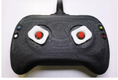
2.3 The designed controler including skin stretch feedback [1] . . . 4
3.1 Three pulling points left and 4 right on one end effector and the space they can reach . . . 7
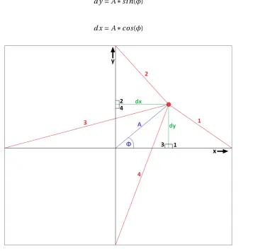
3.2 Four pulling wires (red), the end effector (red dot), amplitude and angle of feed-back (blue) and the displacement with respect to the middle/starting position (green). . . 7
3.3 From left to right, top to bottom, the whole structure seen from different sides. a: Bottom view, b: Side view, c: Top view, d: view under a angle . . . 11
3.4 Arduino controlling the servo’s powered by 4 AA (1,5V) batteries. . . 12
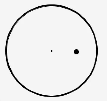
3.5 Visual feedback of the test setup. . . 13
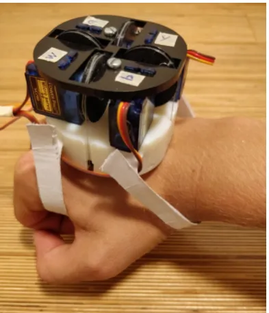
4.1 The structural design placed on a hand. . . 15
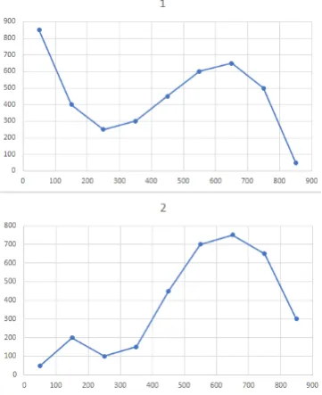
4.2 The paths to be drawn, first and second path of appendix C. . . 16
6.1 Paths created by participant 7, trying to follow the first path with visual (left), haptic (middle) and both kinds of feedback (right). . . 18
6.2 Paths created by participant 7, trying to follow the second path with visual (left), haptic (middle) and both kinds of feedback (right). . . 18
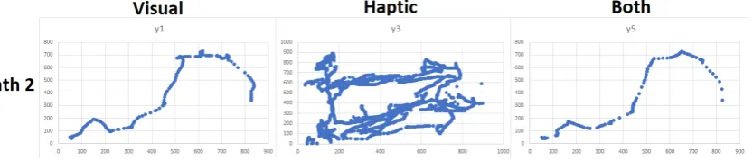
6.3 Paths created by participant 2, for the first and second path. . . 19
6.4 Paths created by participant 5, for the first and second path. . . 19
6.5 Paths created by participant 8, for the first and second path. . . 20
6.6 Error calculated against the time used to complete the path. . . 22
6.7 Error versus time used to complete the first and second path with haptic feedback. 22 B.1 Dimensions of the base (seen from below). . . 27
B.2 Dimensions of the head. . . 28
B.3 Dimensions of the moving end effector. . . 28
C.1 Programmed paths, left column starts left going right, right column starts right going left. . . 29
E.1 Informed consent, to be signed for testing. . . 39
G.1 Results of test with the first path, Left column with visual feedback, middle with haptic, right with both. . . 41
List of Tables
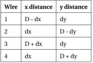
3.1 x and y distances of each wire. . . 8
6.1 Questionnaire of impression of participants. . . 21
vii
Contents
1 Introduction 1
2 Theory 2
2.1 Teleoperation system . . . 2
2.2 Haptic feedback . . . 2
2.3 Skin stretch . . . 3
3 Method 6 3.1 End effector movement . . . 6
3.2 Structural design . . . 8
3.3 Circuitry . . . 10
3.4 Test setup . . . 10
4 Experiment 14 4.1 Realization of structural design . . . 14
4.2 Test setup implementation . . . 14
4.3 Test setup improvements . . . 15
5 Testing 17 5.1 Subjects . . . 17
5.2 User impression . . . 17
6 Results 18
7 Conclusion 23
8 Discussion 24
A Appendix 25
B Appendix 27
C Appendix 29
E Appendix 39
F Appendix 40
G Appendix 41
1
1 Introduction
Endoscopic surgery is used for many applications within the bio-medical world, just to name a few; during pregnancy, for tumor removal or to investigate ear symptoms. Bringing in an endoscope is not without any risks,damaging or perforation of body tissue is one of the risks involved whit an endoscope. Weak body tissue such as colon walls or blood vessels can easily been damaged. Since endoscopes give the doctors much useful information about the cause of certain symptoms or help during surgery it is worth taking this risk. Yet can the health care become even better when the change of this risk is decreased or even better fully taken away. This can be done by giving valuable feedback to the doctor controlling the endoscope. Visual feedback is often used since and endoscope has already a camera placed on it. Force feed-back is another kind of feedfeed-back which is a useful asset to the operator of the system. The last example is vibration feedback, which guides the operator by vibrating on a certain frequency related to the direction and a certain amplitude within the vibration is related to the amplitude needed for the right adjustment of the endoscope. The question arises if there are more useful kinds of feedback which can be used in order to improve the whole system. Since especially haptic feedback is used (force and vibration) would it be interesting to see if a relatively new type of haptic feedback, skin stretch, can be helpful. This research tries to find an answer to the question, is skin stretch a helpful feedback in order to control an endoscope. This is compared with visual feedback and the combination of visual and skin stretch feedback.
2 Theory
To control the end effector of an endoscope an teleoperation system can be used. The control-ler is such that it can control the endoscope towards any direction desired. As it is inside the body and is able to move in any direction it should be controlled carefully. Knowledge about the surrounding is very important here. Skin stretch will be used to provide this. In order to communicate this information are the properties of the skin important. When these are known a system can be designed which makes use of these properties.
2.1 Teleoperation system
[image:10.595.160.418.430.590.2]An teleoperation system is in definition a system where the controller is a certain distance sep-arated from the actuator. The Phantom Omni is a controller which can be used for teleopera-tions. This is a device which can register movement in 6 DOF and generate vibration or force feedback. The system is shown in figure 2.1. The system it self is not of great importance only the background and primary functions of it [3]. The other end of the teleoperation system is often a endoscope but can in theory be any tool useful for any operation, as long as it can be controlled properly inside the body. This way it is possible for a doctor to operate a patient even while he/she is not even near the patient. An important improvement is that specialized doc-tors can operate many people around the world without traveling. Which decreases the cost of a operation of a specialized doctor and increases the amount of operations he/she can perform on a day. Therefore improves it the quality of health care.
Figure 2.1:Phantom Omni [3]
2.2 Haptic feedback
CHAPTER 2. THEORY 3
is that it does not automatically include directional feedback. Which means agreements have to be made about how this is communicated to the user. An other type of haptic feedback which is not delivered by the Phantom Omni is skin stretch. In order to extend the ways of communication the feedback to the user the research will focus on implementing this. This will be done in such a way it can be used with the Phantom Omni.
2.3 Skin stretch
Skin stretch is a relative new method of haptic feedback. Some researches done can be found but also these are in a early stage, to see the examples is left to the reader but will also be dis-cussed later, [8] and [6]. As the name implies is the skin stretched into a certain direction to let the user feel the systems output. The system is via skin stretch able to give information about a direction together with a certain amplitude. Directional feedback can be delivered if the feedback system is created such that it can stretch the skin in multiple directions. This way controlling a device which has to move in a certain direction can be rather easy. The feedback can steer the user towards the right direction and correct if the user moves in the wrong direc-tion. With skin stretch amplitude variation is also possible. This can be done separately, when only the speed of something or the force on something applied by the user is of importance for example, but it can also be used in combination with the directional feedback. This way the system can correct the user strongly if he/she is further off track and more carefully when the job has to be done more precise. Important with both implementations is the sensitivity of the skin, which can be a limiting factor.
2.3.1 Skin sensitivity
As mentioned is skin stretch a new method of haptic feedback therefore is research on it lack-ing. Amplitude and directional skin stretch feedback are researched but both separately. With respect to the amplitude it is known that on the fore arm the skin is able to feel directional skin stretch feedback from only 0,13 mm [6]. This gives a lot of options in the skin stretch feedback. The amplitude with which the skin will be stretched can be really small while the user should still be able to feel it. This means the skin stretch can even be used when the user has to be corrected with a small step. This should be kept in mind when designing the system. Since the threshold is such low the best option during design is to let it out in the beginning and scale the amplitude such that it always surpasses this threshold. Directional precision is the other consideration. The feedback would ideally give the feedback as precise ass possible. There is only a small problem which is that a human can not distinguish one degree of change in the direction of the skin stretched. The smallest angle a human can distinguish is about 15 degrees as was researched by David V. Keyson and Adrianus J.M. Houtsma [8]. This might be a bottle-neck since the preciseness of the feedback goes down. When the user is less then 15 degrees of the ideal path this can not been told via skin stretch feedback to the user. Yet is it still not possible to use any angle smaller than 15 degrees. When for example the user is corrected with 10 degrees the user would not notice it and therefore not adjust its movement. When after a few seconds again a correction of 10 degrees is applied the total correction is 20 degrees. The user would be able to feel it when this was applied in one step, but since it is now done in two steps which both are smaller then the threshold the user will not feel the second change as well. Therefore would the user be off by 20 degrees. When only steps of 15 degrees are considered the maximum deviation between the actual direction and the direction applied to the skin is 7,5 degrees. If the deviation is bigger the system would simply use a step of 15 degrees higher or lower, which decreases the deviation lower than or equal to 7,5 degrees.
these researches seems promising it should be kept in mind that directional skin stretch is often only used in a few directions and without amplitude variation.
2.3.2 Skin stretch until now
[image:12.595.133.435.306.413.2]As already mentioned is skin stretch in a early phase of development. Skin stretch is not used for many applications while it can give a new dimension to many existing technologies. Often are only a few directions used and when done not combined with amplitude variation. The other way around is also done where only amplitude variation is used and directional is left out. A few examples are given below which give an impression of the variety of applications as well of the possible implication methods. One of the applications is the control of a prosthetic arm. Without skin stretch the user can only move it’s arm when looking at it, visual feedback. With the use of skin stretch feedback the user has more feeling about how far the prosthetic arm is turned to the left or right. This is done by a half wheel which is pushed against the skin, when turning the arm the wheel will turn as well pulling the skin to one of the two sides [7], see figure 2.2.
Figure 2.2:(left) Structure with rotatable wheel to deliver skin stretch with amplitude variation, (right)
structure connected to upper arm to deliver feedback. [7]
Another example is with directional feedback but without amplitude variation. In this case skin stretch is used to guide the user in a game. Two actuators which can move the end effectors in 4 directions are placed at the top of the joysticks of a game controller. The controller is used in a fishing game. The feedback gives the user the feeling of the waves witch you would normally feel with your fishing rod. When a fish is on the hook the haptic feedback actuators will mimic the jerking sensation of the fish on the hook. The controller has the same shape as a standard game controller expect for the joysticks where the haptic feedback is included [1], see figure 2.3.
[image:12.595.184.384.598.733.2]CHAPTER 2. THEORY 5
The design of the first example gives the idea that with a simple velcro strap the actuator can be held in place to attach it to the skin. In the meanwhile it is still strong enough to deliver the counter force needed to hold the system in place. The second shows that even with small end effectors skin stretch can still have a valuable impact. Both can be useful in the designing phase.
2.3.3 Improvements
3 Method
In order to improve the system as is described before, 2.3.3, the system needs some require-ments. First of all should the system be able the move the end-effector, which has contact with the skin, in 24 different directions. These directions should be spread out equally around the 360 degrees of a circle in order to let each directional change be 15 degrees. The system should also include amplitude variation. This means the system must be able to vary the amount of stretch applied in any direction. Finally must the system work independently such that it can be used on more applications than only the teleoperation system where it is designed for. Since it is desired to use the system for multiple applications it should also be lightweight and com-pact. A big machine which is not transportable can not always be used in other applications, for example when the person is moving. This means the final weight and compactness should be such that it can be worn on the hand. These in total five requirements are listed below.
1. End effector must be able to move in 24 different directions, each separated by 15 de-grees.
2. End effector must have a controllable distance from the center. 3. System must work independently of teleoperation system. 4. System should be lightweight.
5. System should be compact.
3.1 End effector movement
In order to move the end effector in more than 4 directions a system can be created which pulls the end effector from multiple different sides towards the desired direction. This automatically creates the varying amplitude since it can be pulled more or less towards a certain direction. Each pulling point acquires a actuator. As the requirements mentioned should the system be compact which means as less actuators, and thus pulling points, as possible should be used. Three points seems obvious, with three pulling points the end effector can move freely in a certain space and therefore it fulfills the requirements.
Nevertheless is four pulling points better. Using 4 pulling points requires one more actuator, but as can be seen in figure 3.1 is the space in which the end effector can move better spread out around the center which makes the circle in which it is actually going to move bigger compared to three pulling points. This way the sides of the pulling points (marked by the black box, in fig 3.1) can be placed closer to each other compared to the 3 pulling points structure keeping the circle where the end effector can move the same. When for example 1 cm of movement is desired to the right, the 4 points pulling system can have it’s pulling points placed 2 cm from each other, resulting in a box of 2 by 2 cm. For the three pulling points structure the box has to be 4 by 4 cm big. This means the total surface of the structure is 4 times as big compared to the 4 pulling points system. Therefore it is chosen to use the 4 pulling point system. Pulling actuators can be found smaller than the saving of 8 cm2which means even though one actuator more is used, the structure is still compacter with 4 pulling points.
3.1.1 Wire lengths
CHAPTER 3. METHOD 7
Figure 3.1:Three pulling points left and 4 right on one end effector and the space they can reach
been calculated with the amplitude and the direction. This displacement is depicted as dx for the displacement in the x direction and dy in the y direction. When the end effector is moved to the right is this defined as positive displacement, the same holds for the up direction for the y displacement. The displacement of dy and dx can be described with the following equations, 3.1 and 3.2. Sinceφis chosen to be the angle between the desired path and the positive x-axis an angle of 0 degrees is equal to a movement to the right. This has to be kept in mind when designing the test case and also when the setup is used in other cases.
d y=A∗si n(φ) (3.1)
[image:15.595.134.492.361.716.2]d x=A∗cos(φ) (3.2)
Figure 3.2:Four pulling wires (red), the end effector (red dot), amplitude and angle of feedback (blue)
When the end effector is in the middle, this is the case when no stretch is applied, the distance between the end effector and each pulling point is equal. This distance determines the moving distance of the end effector and the dimensions of the structure, for now is this distance labeled as "D". With the use of figure 3.2 it is possible to determine the separation of the end effector and the pulling point in the x and y direction. This is, for example, for the first wireD−d xin the x direction andd yin the y direction. For all wires are the different distances given in table 3.1.
Table 3.1:x and y distances of each wire.
Wire x distance y distance
1 D - dx dy
2 dx D - dy
3 D + dx dy
4 dx D + dy
With these parameters known can the Pythagorean theorem been used to calculate the length of each wire needed to reach a certain position. The wires are simply the hypotenuse of the right angled triangles marked with the black numbers 1 to 4 in figure 3.2. Using the x and y distances of table 3.1 gives the following equations and thus wire lengths for each of the four wires.
w i r e1=
q
(D−d x)2+d y2 (3.3)
w i r e2=
q
d x2+(D−d y)2 (3.4)
w i r e3=
q
(D+d x)2+d y2 (3.5)
w i r e4=
q
d x2+(D+d y)2 (3.6)
When no stretch is applied the wire lengths of all pulling points are equal toD, this is the start point. When a wire length is shorter thanD the actuator should pull the wire back with an amount ofD−w i r el eng t h. When it is longer thanD the actuator should release some wire, the amount of wire to be released is equal tow i r el eng t h−D in order to make the total wire again equal tow i r el eng t h. This means the actuators should always release or pull with the difference betweenDand the desired wire length. When pulling wire in is counted as the neg-ative of releasing wire, the amount of wire to be released can be given with equation 3.7.
r el ease=w i r el eng t h−D (3.7)
3.2 Structural design
CHAPTER 3. METHOD 9
well between the amount of space to move the end effector and the compactness of the system as a whole. The design consists of three important parts; the base in which the end effector can move and the actuators can be placed, actuators to move the end effector and an moving end effector which is attached to the skin. The design of the whole structure is given below, the total design is given in figure 3.3.
3.2.1 Base
It is chosen to 3D print the base, this because it can be done relatively fast and precise. The base shall be made out of objet, the 3D printer present can print most precisely with this material. In order to keep the structure compact it is chosen to have the actuators on top of the moving space of the end effector. This way the actuators do not make the base bigger on the sides but on the top of the structure. Since the height is not a big deal, because the structure is placed on the skin with the height pointing outwards, this is the best option to keep the structure compact. This choice automatically means that the end effector has a sort of roof on top of its moving space. The structure will be placed on the back of the hand. With the average hand size width being 8,4 cm [2]. It is chosen that the structure should be a bit smaller, the surface of the structure will be 6 by 6 cm in order to fit on each hand. The moving space is chosen to be 4 by 4 cm, this is done by testing skin stretch with the thumb. Measuring the amount of skin stretch applied on the backside of the hand which is still comfortable gives 2 cm. The side walls of the structure can still be 1 cm with these dimension which gives enough strength to hold the roof. The corners are rounded in order to fit better on the hand. The roof should hold the actuators and counter act the forces applied on it from the actuators without bending. Since 1 cm is in theory strong enough for the walls it should be strong enough as well for the roof of the base. With the space beneath if 1 cm in order to move the end effector becomes the base 6 by 6 by 2 cm, which is indeed a compact structure. Trough the roof of the base are made two holes to insert the velcro. This way it can be strapped around the hand. The base is shown from beneath with the described dimensions in appendix B and in figure 3.3.
The base has to keep the actuators stable. Since they are placed on the base it is chosen to have a roof on the actuators which is screwed tight to the base to clamp the actuators. This roof has to be strong but it does not really matter how precise it is created, because the only function it has is to hold the actuators stable. This is why it shall be cut out of delrin. Which is a strong material but since it is laser cut it is created less precise than the base. An advantage of cutting it is that it can be produced very fast. The roof has gaps in it to fit the connecting points of the actuators and to give the rotating wheels some space, see appendix B, the dimensions of these gaps are determined in section 3.2.2. Whit two screws (3 mm) it is screwed to the base where two square holes are made (5,5 mm by 5,5 mm) where the bolts can be placed. As can be seen in appendix B. The end effector will be connected to the actuators with wires. Since the end effector is under the base the walls need gaps to let the wires trough. In these gaps a small wheel is placed in order to lower the friction. The gaps are 3.1 mm wide (see appendix B) and the wheels placed in it are 3 mm wide with a radius of 2,5 mm. A small gap is made in the wheel, radius of 1 mm, in order to connect it to the base and still let it rotate. These wheels are cut out of objet since the preciseness of the wheels is not that important and laser cutting can be done quickly.
3.2.2 Actuators
have a max rotation of 180 degrees, the wheel should be big enough to move the wire 2 cm’s in 90 degree, in order to pull and release enough wire. The circumference of the wheel should therefore be 8 cm. The radius and thus the arm which is used to calculate the amount of force delivered by the actuator can be calculated with 3.8.
r=ci r cum f er ence
2∗π =
8
2∗π=1, 273cm (3.8)
With the radius being 1,273 cm the force delivered by the actuator to the end effector (assum-ing the wire has negligible resistance) is equal to 17.651.273=13.86N. This means the actuator can deliver much more force than in the previously mentioned research, about 9 times as much, and therefore that the actuators should be strong enough to actually pull the skin. In order to prevent the wire from falling of the wheel, are the sides of the wheel made a little bit higher. This does not influence the system since the wire is not on top of it but it prevents the system from failing. A small gapp is made in these small walls to let the wire out to the side. A hole in the wheel makes it possible to fasten the wire with a screw to the wheel as can be seen in figure 3.3 c and d. The connectors of the actuators are 11,8 mm by 2,5 mm, therefore have the holes in the base and head the same dimensions. The holes for the wheels are determined empirical, with some space left in order to prevent friction.
3.2.3 End effector
The end effector should be big enough to hold a sticker which can move the skin without slip-ping, but the dimensions of it are limited by the space it has within the base. The sticker is made of a special tape which sticks well to the skin, leukoplast [4]. Double sided tape is used to connect the leukoplast to the end effector. When tried it can pull the skin properly without slipping when a square of 1 by 1 cm is used. The end effector will therefore be 1 by 1 cm. Leav-ing the space it can move towards one of the sides not 2 cm but 1,5 cm. The circle in which the end effector can move with an equal amplitude towards every direction has an amplitude ofp8 cm, which can be calculated with figure 3.2. The wires are pulled trough the end effector and with a knot they are secured. There are 4 holes made in the end effector to make this possible, as can be seen in figure 3.3a in the middle.
3.3 Circuitry
The servo motors runs when it is powered with a voltage between 4,8 V and 7,2 V, the stall cur-rent is about 650 mA [5]. Since 4 simple AA (1,5 V) batteries can provide both this is the chosen option. The control of the servo is done with an arduino uno. These have a build in library for servo motors which makes it easy to use and can be used in many cases independently of the teleoperation system which was one of the requirements.. The library gives the correct PWM signal out when a certain angle between 0 and 180 degrees is set. The arduino is connected to a laptop which poweres it but also provides the connection to the test setup which will run on the computer. The circuitry is given in figure 3.4. The arduino can be used to map the desired angle and amplitude to the correct wire lengths. When the correct wire lengths are calculated it can map those to the correct angle of the servo and tel the servo’s to adjust themselves to this angle.
3.4 Test setup
CHAPTER 3. METHOD 11
Figure 3.3:From left to right, top to bottom, the whole structure seen from different sides. a: Bottom
view, b: Side view, c: Top view, d: view under a angle
Figure 3.4:Arduino controlling the servo’s powered by 4 AA (1,5V) batteries.
1. Software should create a path which the user has to follow.
2. The test setup should test visual feedback, haptic feedback and the combination of both. 3. Software should communicate the right angle and amplitude to the arduino.
4. The path of the user has to be stored.
3.4.1 Software
The test program is written within the program processing 3 [10]. Processing can be down-loaded for free from their website [10], has a simple way of communicating with the arduino and is able to write data in an excel (.CSV) file which makes the data storage and analysis much easier. This choice of software helps to acquire already two of the four requirements.
Ten paths are created which the user has to follow. The first 5 path’s are unique while the second 5 are the same as the first five but than mirrored across the x or y axis. The first five paths all start at the left while the second five start at the right. This way the user is tested with feedback in every direction and can a comparison been made between feedback going to the left or right and feedback going up or down, while the difficulty of the path stays the same. The paths exist of a few points which have to be hit by the user to go to the next point. The paths chosen with their points are given in appendix C.
CHAPTER 3. METHOD 13
track. All errors are summed which give the end result of the preciseness of the users handling and thus about the quality of the feedback. This is done with the function "c al cEr r or" as can be seen in appendix D. Each tenth of a second are the x and y location of the user stored in a table. In the end this table is converted to a excel (.CSV) file. This makes it possible to reconstruct the path of the user by plotting the x and y values. This path can then be compared with the path which was predefined and the paths of the different kind of feedback.
3.4.2 Connecting the skin stretch actuator
The arduino which controls the actuators can calculated the desired position of each servo if it has the desired angle and amplitude of the end effector. Since these both can be calculated out of the current mouse position and the desired end position this can be implemented rather easily. Function "c al c An Am" (see appendix D) first calculates the delta x and y between the two points after which it uses the pythagorean theorem to calculated the amplitude. With the use of the inverse tangent the angle is calculated after which it is rounded to a multiple of 15 degrees. Both are communicated to the arduino in the following form, when for example the angle is 180 degrees and the amplitude is 1,2 cm is this communicated as "180|120". The separation mark "|" indicates the end of the angle and the beginning of the amplitude value.
3.4.3 Visual feedback
[image:21.595.211.391.514.689.2]To compare the results of the haptic feedback a visual feedback is implemented as well. This one works exactly the same as the skin stretch feedback but now is the end effector a small dot in a circle instead of a moving end effector attached to the skin, as depicted in figure 3.5. The point moves in the direction the mouse should do as well, which means in figure 3.5 the mouse should move to the right. When it moves further from the middle the user is further away from the desired end point. The visual feedback is chosen to be this way because the only difference on the quality of the feedback should be the communication method to the user. When something else influences this the results are less valuable. The visual feedback is provided with the function "c al cV i sual" see appendix D. The function simply draws the circle and the middle point, after which the moving point is just a down scaled version of the actual difference in x and y direction of the mouse and desired end point.
4 Experiment
The structural design, circuitry and test setup are theoretically complete. The only step left is to actually create the design, connect it to the test setup and validate the requirements. After this the system should be ready to use and can it be tested to see the impact of it.
4.1 Realization of structural design
As it turned out after 3D printing was the structure well designed. The actuators fit gaps as well as the wheels on the servo motors and the screws which hold everything together. It was not sure if the structure would be strong enough and would not bend because of the great gape beneath the base. The base turned out to be very strong and not bend at all. Which means the walls and roof are chosen big enough and might even be smaller if this is desired. The wires fit within the gaps of the end effector and are also easily connected with a screw to the wheel. The system is validated with the requirements given in chapter 3, which are here listed below as well.
1. End effector must be able to move in 24 different directions, each separated by 15 de-grees.
2. End effector must have a controllable distance from the center. 3. System must work independently of teleoperation system. 4. System should be lightweight.
5. System should be compact.
For the first requirement is the end effector send to multiple different locations in order to see its movements. The arduino calculated the angles of the servo motors correctly and moved the end effector rapidly to the correct location. Which means this requirement is met. With this is immediately the second requirement fulfilled, since the end effector was send to different locations which also had different amplitudes. The system is designed to work on an arduino uno. The communication towards it can be done in many ways (even wireless) therefore can the system be used for any purpose independently of the teleoperation system. As can be seen in figure 4.1 is the system compact enough to fit on the hand, or upper/lower arm if desired. The total weight of the structure equals 127 grams which makes it easily wearable.
4.2 Test setup implementation
As the structural design works as desired and the circuitry does as well since the end effector was able to move to the desired angle with the desired amplitude, is the design connected to the test setup software. In first instance the end effector did not move or try to move at all. This because the feedback was send with 60 Hz, overloading the connection between the computer and the arduino. In order to prevent this and give the servo motors enough time to reach the destination is a counter build in. The counter makes sure the feedback is updated two seconds. This works properly and the motors have indeed enough time to reach their final value and move the end effector to the right position. The software had some requirements as well, which are given in section 3.4.1 and are listed below in the same way.
1. Software should create a path which the user has to follow.
CHAPTER 4. EXPERIMENT 15
[image:23.595.204.401.103.332.2]4. The path of the user has to be stored.
Figure 4.1:The structural design placed on a hand.
The software creates the path properly. One problem occurred when the x and y coordinates where initialized. When x and y are both set to zero the point is in the upper left corner, and when x and y are set to the width and height (900 by 900) the point occurs in the corner down right. Therefore seemed all paths flipped across the x axis. This was easily solved by changing the coordinates from its original value to 900 minus the original value. The path is created and the points hidden, only the previous point is visible in order to prevent the user from seeing the path and guessing where the next point should be. Therefore is this requirement met. A test case is done where the user can get familiar with both types of feedback. After this are the first trials done with visual feedback, then the haptic feedback and finally both simultaneously. Every case works as desired and the program switches easily between the different feedback types, with which it fulfills the requirement. In order to test the angle and amplitude com-municated to the arduino is the structural design placed on a glass table. The mouse is moved deliberately around the desired point to see if the end effector moves in the right direction. This is indeed the case which makes the system fulfill this requirement as well. The last requirement is tested by doing the whole test after which the document created is opened and the data is plotted. The plots give the path which the mouse has made. Therefore it can be said that the software written works as desired and therefore the total system. The system is ready to use to test the usefulness of the skin stretch feedback.
4.3 Test setup improvements
After the first few trials it became clear that the structural design needed some adjustments. The amplitude variation was not noticeable at all. People could not distinguish the direction when the amplitude was lower than 50 mm. When increasing the amplitude people did not feel enough change to identify when the amplitude was high or low. The only few cases people where able to distinguish the variation was when the variation was more than 60 millimeters which made it almost impossible to use it. Therefore it was chosen to let the amplitude vari-ation out.
people get used to the tension and after a few seconds they did not know which direction they should move. Therefor it was chosen to change the directional feedback to pulses. Each two seconds the end effector would move in the right direction, stay there for a second, move back and wait for the next direction to move in. This worked better since people started to recognize the directions in which the feedback moved. A disadvantage of it was when the end effector moved back people tended to move in this direction as well. Which is exactly the opposite direction of which they should actually move. Therefore is a new method applied. Where the end effector first moves slowly towards the direction in which the user should move the mouse after which it gets fast back to the middle point. This way users could distinguish the move-ment in the right direction and when the end effector was going back. This worked better since people could sometimes follow parts of the path, nevertheless where people sometimes left in the dark.
[image:24.595.195.376.311.533.2]Because it took people a long time finishing a path with the haptic feedback it is chosen to lower the amount of paths which the user has to make. First the user should make ten different paths, this is lowered to two paths. The used paths are the first two of appendix C and given below in figure 4.2 as well.
17
5 Testing
After the participant have signed the informed consent, see appendix E, they are asked to draw the given paths. As mentioned before in 3.4.1 has each participants two test cases in order to get familiar with the soft and hardware. People are able to train them selves here. It is possible to close your eyes to ignore the visual feedback. This way people are already trained a little with the haptic feedback before the actual test starts. The test case starts when the mouse hits the first (visible) dot. Then the visual and haptic feedback guide the user towards the next point. If the location of the next point is reached it becomes visible and the previous point disappears, this to prevent the user from recognizing a path. The feedback guides the user again to the next point until all 8 points of one path are touched. When this is done the new trial can be started by again moving the mouse to the new (visible) start point. When the user has finished the two test cases this way the real test is going to start. These trials work the same as the described test cases, the only thing which changes is the form of feedback. First is the user asked to draw the first and second path with the visual feedback. The visual feedback shows the user which direction he/she has to move. This is done as mention in section 3.4.3 where figure 3.5 means the user has to move to the right. This because the big black dot is at the right of the middle. At the moment the user is done with these two trials the same paths come in again but now the user has to draw them with haptic feedback. The user can again close his/her eyes to focus more on the haptic feedback. Nothing is showed on the screen only the previous point hit by the user. Finally the user draws the same paths again with both kinds of feedback at once. Here the user can chose to trust fully on one of both types of feedback but can also use the combination to be more confident about the direction to move in.
5.1 Subjects
The study included N= 10 participants (40% female, 60% male) between the ages 18-58 (Mag e=
33.54,SDag e=16.41) who voluntarily participated in the study. The average BMI of the
parti-cipants was 25.65 (sdB M I=3.07) influencing the elasticity of the skin. Participants were
selec-ted through convenience sampling. The sample only included people with a Dutch nationality. Participants did not have to comply with certain criteria to participate in the study except that the participant should be able to feel stretch applied on their skin, being able to see the visual feedback and move their hand. Participants had to be over 18 years old and be able to fill in an English questionnaire to participate in the study.
5.2 User impression
6 Results
In order to answer the question if haptic skin stretch feedback is a helpful tool to control an endoscope, the paths which are created by the users with skin stretch feedback are compared with the paths created with visual feedback and with both kinds of feedback. All paths created by the participants are given in appendix G.
Each participant tried to create the first and second paths of appendix C three times. Once with visual feedback, once with haptic feedback and once with both kind of feedback.
[image:26.595.80.498.344.431.2]It can be seen that some people had a hard time following the path with the haptic feedback, appendix G. Participant 7 is one of those for example, figure 6.1 shows the paths made by this participant for path 1. With the visual feedback the user was able to stay close to the desired path. Only a few strange hick-ups can be seen for example aroundx=200 andx=600. With the haptic feedback the participant moved in almost any direction touching almost every point on the screen. This indicates clearly that the directions of the haptic feedback where difficult to distinguish for this person. Nevertheless can it be seen that in the last case the path of the user is more smooth compared to visual feedback only. With the second path the same result
Figure 6.1:Paths created by participant 7, trying to follow the first path with visual (left), haptic (middle)
and both kinds of feedback (right).
[image:26.595.82.499.579.668.2]showed. Figure 6.2, shows the result of the second path of participant seven. Indication again he/she had a hard time following the correct path with haptic feedback, but being more secure when both are used. Even though there seems to be a small improvement in the usage of the haptic feedback. There even is a slanted line fromx=200,y=100 tox=500,y=300 following the right direction.
Figure 6.2: Paths created by participant 7, trying to follow the second path with visual (left), haptic
(middle) and both kinds of feedback (right).
CHAPTER 6. RESULTS 19
Figure 6.3, shows the results of participant 2. These are highlighted since it can be seen clearly that a participant is able to improve him/herself with the haptic feedback. As the tests where done people mentioned they where learning while drawing the paths. Figure 6.3 shows that while the result of the visual path stays nearly the same the participant clearly improves in the haptic and combination of both kinds of feedback. As almost no path can be distinguished in the first path with haptic feedback, can it be done in the upper right part with the second path.
Figure 6.3:Paths created by participant 2, for the first and second path.
[image:27.595.89.520.498.667.2]Participant 5 and 8 drew much better paths compared to all the other participants. The paths of participant 5 are shown in figure 6.4. Both paths can be recognized in all kinds of feedback. The haptic feedback paths are clearly better compared with others, nevertheless is this participant no other than the rest. The same holds for this participant, he/she draws better/more secure with both kinds of feedback and he/she improves the haptic feedback (since the second path is better) while doing the test.
Figure 6.4:Paths created by participant 5, for the first and second path.
Figure 6.5:Paths created by participant 8, for the first and second path.
up/down or left/right. The first statement still holds for this participant as the paths with both kind of feedback are still better compared to visual only.
The impression of the users is given in table 6.1. As can be seen have people different opinions about the system, if it is intuitive or not, easy to use or the speed with which people can learn it. Most of the people think they need more training which is supported by the data of the test case as well. The visual feedback and the combination of both are felt as the best options. Where visual only is felt slightly better than the combination of both while the paths show that it is the other way around. People where well isolated during the test, this is important since people can focus better this way on the feedback. Some people felt tired some did not at all, therefor is the mean 3.00 but is the variance 1.24 which is high.
Finally is the calculated error and the time plotted against each other. The result is given in figure 6.6. In general it can be seen that within the visual feedback the error stays much lower compared to the haptic feedback. When both feedback types are used it can be seen that most of the points are in an even lower range than with the visual feedback. Where the visual feed-back has still a few errors between ten thousand and twenty thousand, are there only two points in this range when both kinds of feedback are used. Where with the haptic feedback a relation could be seen with increasing time goes increasing error, is this harder to imagine with the other two options.
CHAPTER 6. RESULTS 21
Table 6.1:Questionnaire of impression of participants.
Question Mean
answer
Standard
deviation
answer
The system was intuitive 3.08 1.21
The system was easy to use, 3.15 0.95
I needed support by the test administrator to be able to use the
system,
2.69 1.38
Most people would quickly learn how to use the system, 3.23 1.19
I felt confident using the system, 2.31 0.99
I needed more training to confidently use the system, 4.38 0.92
Sound from the device caused disturbance while performing
the experiments,
2.31 1.38
I was well-isolated from external influences, 4.15 1.10
At the end of the experiment I felt tired, 3.00 1.24
The visual feedback gave a good representation of in which
dir-ection I had to move,
4.62 0.62
With the visual feedback I performed the best, 4.77 0.42
The haptic feedback gave a good representation of in which
dir-ection I had to move,
2.69 0.99
With the haptic feedback I performed the best, 1.31 0.46
The combination of both kinds of feedback gave a good
repres-entation of in which direction I had to move,
4.08 1.07
Figure 6.6:Error calculated against the time used to complete the path.
[image:30.595.82.495.381.505.2]23
7 Conclusion
The results in appendix G show that people had a hard time creating the correct path with haptic feedback. An easy conclusion would be that it is not useful at all. Nevertheless would this ignoring the real message in the results. As was depicted where some people able to im-prove them selves. There where even examples of people who had evolved during the test case and drew an rather astonishing path the second time. In the impression questionnaire the par-ticipants agreed on needing more training. Meaning they also believe in the fact they could get used to the system even more. Finally are the error and time plots given of the first and second path with haptic feedback which showed an improvement as well. Therefor can it be concluded that unless that people sometimes have a hard time figuring out which direction to move in it is possible to improve yourself by training, which leads to better results. How much training is needed per person and on which variables the amount of training depends has to be found out with more research.
The questionnaire showed that participants found the visual feedback a little better than com-bination of both. Which is in contradiction with the improvements people showed in drawing their paths with both types of feedback compared to visual and haptic feedback used separ-ately. As is shown with figure 6.1, and can be seen with more cases in appendix G. Also the error comparison done with figure 6.6 showed that people give in general better results when both feedback’s are combined. Therefor can it be concluded that people stay better within the path when both types of feedback are used simultaneously, even though people do not recognize this.
8 Discussion
The research consists of two parts, the design of the skin stretch actuator and testing the influ-ence of skin stretch applied to the human skin with this design. Since both are done was less time spend on validating the design. The requirements are met and therefore does the system what it is supposed to do. On the other hand is it never tested if it is able to move the given 0,13 mm in section 2.3.1. If this was not the case the design needs to be improved. As well as the accuracy of the angles which the system makes. These are never validated since it was more important to move on and test it with the participants. If the design of the system and testing the influence of it would be separated both can be done with more detail. This would give even more information about the system and what the best method might be to apply skin stretch. Since the research started with the design of the haptic feedback system there was no option to compare different skin stretch methods. If this was desired many more different systems had to be designed which would be very time consuming. Nevertheless would this have been inter-esting and could give it a lot if insight in what has the most influence on the skin and which is the best noticeable. Then the question if it can be used for the teleoperation system could be answered even better. Therefore is more research needed in order to create, test and compare different methods of applying skin stretch feedback.
25
A Appendix
const double pi = 3.14159265359; // i n s e r t pi
const double distance = 2 . 0 ; // Distance between side and midle of moving space
S t r i n g angleIn ; // Input of the s e r i a l connection
double S0 _dis t = 0 . 0 , S1 _dist = 0 . 0 , S 2_ di st = 0 . 0 , S 3 _d i s t = 0 . 0 ; //Moving distance
i n t an_s0 = 0 , an_s1 = 0 , an_s2 = 0 , an_s3 = 0 ; // Angles of each servo to move
double ampl = 1 . 0 , angle = 0 . 0 ;
# include <Servo . h>
Servo s0 , s1 , s2 , s3 ;
i n t z0 = 80 , z1 = 90 , z2 = 120 , z3 = 9 0 ; // Zero p o s i t i o n s
void setup ( ) {
S e r i a l . begin ( 1 1 5 2 0 0 ) ;
s0 . attach ( 4 ) ; // servo 0 attached to pin 4 y
s1 . attach ( 5 ) ; // servo 1 attached to pin 5 g
s2 . attach ( 6 ) ; // servo 2 attached to pin 6 w
s3 . attach ( 7 ) ; // servo 3 attached to pin 7 b
s0 . write ( z0 ) ; // t e l l servo to go to the s t a r t i n g position
s1 . write ( z1 ) ;
s2 . write ( z2 ) ;
s3 . write ( z3 ) ;
}
void loop ( ) {
i f ( S e r i a l . a v a i l a b l e ( ) > 0) { //Check f o r data on the s e r i a l port
angleIn = S e r i a l . readString ( ) ; //Read s t r i n g of s e r i a l port
angle = pi / 180.0 * angleIn . toInt ( ) ; // convert angle to r a d i a l
// c a l c u l a t e dx and dy
double dx = ampl * cos ( angle ) ;
double dy = ampl * sin ( angle ) ;
//Use pythagoras to c a l c u l a t e the desired wire length
S0 _di st = s q r t (pow( ( distance − dx ) , 2) + pow( dy , 2 ) ) ;
S1 _di st = s q r t (pow( dx , 2) + pow( ( distance − dy ) , 2 ) ) ;
S2 _di st = s q r t (pow( ( distance + dx ) , 2) + pow( dy , 2 ) ) ;
//Use the wire length to get the desired angle .
an_s0 = round ( ( ( S 0_di st − 2) / 2) * 90 + z0 ) ;
an_s1 = round ( ( ( S 1_di st − 2) / 2) * 90 + z1 ) ;
an_s2 = round ( ( ( S 2_di st − 2) / 2) * 90 + z2 ) ;
an_s3 = round ( ( ( S 3_di st − 2) / 2) * 90 + z3 ) ;
// Average middle value with desired value
//Where middle value importance decreases and desired increases
i n t steps = 2 0 ;
f o r( i n t i = 1 ; i <=steps ; i ++){
s0 . write ( ( ( ( steps−i ) * z0 )+( i * an_s0 ) ) / steps ) ;
s1 . write ( ( ( ( steps−i ) * z1 )+( i * an_s1 ) ) / steps ) ;
s2 . write ( ( ( ( steps−i ) * z2 )+( i * an_s2 ) ) / steps ) ;
s3 . write ( ( ( ( steps−i ) * z3 )+( i * an_s3 ) ) / steps ) ;
delay (600/ steps ) ;
}
delay ( 4 0 0 ) ;
// Move servo back to the middle
s0 . write ( z0 ) ;
s1 . write ( z1 ) ;
s2 . write ( z2 ) ;
s3 . write ( z3 ) ;
}
}
27
[image:35.595.160.445.138.424.2]B Appendix
Figure B.2:Dimensions of the head.
[image:36.595.143.429.434.719.2]29
[image:37.595.145.461.138.624.2]C Appendix
D Appendix
//The user has to foow a c e r t a i n l i n e by connecting the dots with i t s mouse . //The dots are not v i s i b l e , the v i s u a l feedback or haptic
// skin s t r e t c h feedback s h a l l guide the user towards the point . // Lines are pre defined in matrixes .
// F i r s t a t e s t c a s e i s done , a f t e r that i s f i r s t only v i s u a l feedback used , // then skin s t r e t c h feedback and l a s t l y both simultaniously .
// Finaly are the e r r o r and time score shown .
// Error i s c a l c u l a t e d when the user i s to f a r out of the path
//he/ she should follow , by multiplying the angle with the amplitude of the e r r o r .
// Created by C h r i s t i a n Ewout Baars ( Student number s1704532 ) // In order of RAM ( Robotics And Mechatronics )
// University of Twente . //30−06−2018
import processing . s e r i a l . * ; // Library f o r s e r i a l connectionSerial port ;
S e r i a l port ;
S t r i n g name = " p a r t i c i p a n t _ 1 ";
// Test amount/ t e s t s counter / maximum points per t e s t / Current point in t e s t
i n t testAmount = 30 , testCnt = 0 , pointMax = 8 , pointCnt = 0 ;
//Minimum amplitude to h i t point / with of path ( angle )
i n t space = 4 , angleSpace = 1 5 ;
// Amplitude to previous point / Amplitude to next point / // angle to next point / angle between previous and next point .
i n t ampToPrev = 0 , ampOut = 0 , angleOut = 0 , pointAngle = 0 ;
f l o a t pi = 3.14159265359; // i n s e r t pi
i n t timer = 0 ; // time storage
i n t e r r o r = 0 ; // Error storage
i n t[ ] score = new i n t[ testAmount ] ; // Score storage
[image:38.595.77.497.108.755.2]i n t[ ] timeScore = new i n t[ testAmount ] ; //Time score storage
Table pathStore ;
i n t Xplace = 0 , Yplace = 0 ; //X and y of next point
i n t xPrev = 0 , yPrev = 0 ; //X and y of previous point
f l o a t deltaX = 0 . 0 , deltaY = 0 . 0 ; // Difference between next point and mouse .
// counters used f o r sample taking
i n t frameCnt= 0 , frameFeedback = 120 , storeCnt = 0 , feedbackCnt = 0 ;
APPENDIX D. APPENDIX 31
PFont font ; // font f o r t e x t displ ay
// Test points , f i r s t i s y second i s x .
i n t[ ] [ ] t e s t = { { 5 0 , 500 , 650 , 600 , 450 , 300 , 250 , 400 , 8 50 } ,
{ 5 0 , 150 , 250 , 350 , 450 , 550 , 650 , 750 , 8 5 0 } } ;
// T r i a l x points , 1 row i s 1 path
i n t [ ] [ ] xPath = { { 5 0 , 150 , 250 , 350 , 450 , 550 , 650 , 750 , 8 50 } ,
{ 5 0 , 150 , 250 , 350 , 450 , 550 , 650 , 750 , 850} ,
{ 5 0 , 150 , 250 , 350 , 450 , 550 , 650 , 750 , 850} ,
{ 5 0 , 150 , 250 , 350 , 450 , 550 , 650 , 750 , 850} ,
{ 5 0 , 150 , 250 , 350 , 450 , 550 , 650 , 750 , 850} ,
{8 50 , 750 , 650 , 550 , 450 , 350 , 250 , 150 , 5 0 } ,
{8 50 , 750 , 650 , 550 , 450 , 350 , 250 , 150 , 5 0 } ,
{8 50 , 750 , 650 , 550 , 450 , 350 , 250 , 150 , 5 0 } ,
{8 50 , 750 , 650 , 550 , 450 , 350 , 250 , 150 , 5 0 } ,
{8 50 , 750 , 650 , 550 , 450 , 350 , 250 , 150 , 50}
} ;
// T r i a l Y points , 1 row i s 1 path
i n t [ ] [ ] yPath = { { 5 0 , 500 , 650 , 600 , 450 , 300 , 250 , 400 , 8 50 } ,
{8 50 , 700 , 800 , 750 , 550 , 200 , 150 , 250 , 600} ,
{1 00 , 500 , 650 , 750 , 800 , 750 , 650 , 500 , 100} ,
{1 00 , 100 , 800 , 800 , 100 , 100 , 500 , 500 , 800} ,
{8 00 , 650 , 200 , 300 , 600 , 100 , 400 , 500 , 100} ,
{ 5 0 , 500 , 650 , 600 , 450 , 300 , 250 , 400 , 850} ,
{8 50 , 700 , 800 , 750 , 550 , 200 , 150 , 250 , 600} ,
{8 00 , 400 , 250 , 150 , 100 , 150 , 250 , 400 , 800} ,
{1 00 , 100 , 800 , 800 , 100 , 100 , 500 , 500 , 800} ,
{8 00 , 650 , 200 , 300 , 600 , 100 , 400 , 500 , 100}
} ;
void setup ( ) {
// Create frame
s i z e (900 , 9 0 0 ) ;
frameRate ( 6 0 ) ;
background ( 2 4 4 ) ;
font = createFont (" A r i a l ", 30 , true) ; // Create font
pathStore = new Table ( ) ;
p r i n t l n (" A v a i l a b l e s e r i a l ports : ") ; // P r i n t the s e r i a l ports
f o r (i n t i = 0 ; i < S e r i a l . l i s t ( ) . length ; i ++) {
p r i n t (" [ " + i + " ] ") ; p r i n t l n ( S e r i a l . l i s t ( ) [ i ] ) ;
}
port = new S e r i a l (t h i s, S e r i a l . l i s t ( ) [ 0 ] , 115200);//Make connection to s e r i a l port
}
void draw ( ) {
background ( 2 4 4 ) ;
textFont ( font , 3 0 ) ; // Reset font i f changed
f i l l ( 0 ) ;
//0= s t a r t , //1= t e s t c a s e ,
//2=prepare f o r next t r i a l , //3=do next t r i a l ,
//4=done/showscore
switch( s t a t e ) {
// ___________________Start___________________
case 0 :
t e x t ("The t e s t i s going to s t a r t ", 50 , 4 0 ) ;
t e x t (" I t c o n s i s t s of " + testAmount + " paths ", 50 , 1 0 0 ) ;
t e x t ("The feedback w i l l help you", 50 , 1 6 0 ) ;
Yplace = t e s t [ 1 ] [ pointCnt ] ; // Set x and y
Xplace = t e s t [ 0 ] [ pointCnt ] ;
calcAnAm ( ) ; // Calculate angle and amplitude between mouse and next point .
e l l i p s e ( Xplace , Yplace , space , space ) ; //Show point
i f (ampOut<=space ) { // I f mouse i s close to the point s t a r t the t e s t c a s e
pointCnt +=1;
s t a t e += 1 ;
timer = m i l l i s ( ) ; // r e s e t timer
}
break;
// ___________________Testcase___________________
case 1 :
t e x t (" Testcase ", width/2−20, 4 0 ) ;
APPENDIX D. APPENDIX 33
Xplace = t e s t [ 0 ] [ pointCnt ] ;
Yplace = t e s t [ 1 ] [ pointCnt ] ;
//Show previous point
e l l i p s e ( t e s t [ 0 ] [ pointCnt−1] , t e s t [ 1 ] [ pointCnt−1] , space , space ) ; //Show point
calcAnAm ( ) ;// Calculate angle and amplitude between mouse and next point .
i f (ampOut<=space ) {// I f mouse i s close to the point go to next
pointCnt +=1;
i f ( pointCnt >pointMax ) { // I f a l l points done , s t a r t f i r s t t r i a l .
s t a t e +=1;
timer = m i l l i s ( ) ;
pointCnt =0;
}
} e l s e {
hapticFeedback ( ) ; // Give haptic feedback to user
c a l c V i s u a l ( ) ; //Show v i s u a l feedback
}
break;
// ___________________Start tr i a l _ _ _ _ _ _ _ _ __ _ _ _ _ _ _ _ _ _
case 2 :
t e x t (" T r i a l " + testCnt + " i s going to s t a r t ", 50 , 4 0 ) ;
//Update X and Y
i f ( testCnt < testAmount /3) { // Visual t r i a l s
Yplace = yPath [ testCnt ] [ pointCnt ] ;
Xplace = xPath [ testCnt ] [ pointCnt ] ;
} e l s e i f ( testCnt < testAmount *2/3) { // Haptic t r i a l s
Yplace = yPath [ testCnt−testAmount / 3 ] [ pointCnt ] ;
Xplace = xPath [ testCnt−testAmount / 3 ] [ pointCnt ] ;
} e l s e { // Visual and haptic t r i a l s
Yplace = yPath [ testCnt−testAmount *2 /3 ] [ pointCnt ] ;
Xplace = xPath [ testCnt−testAmount *2 /3 ] [ pointCnt ] ;
}
calcAnAm ( ) ;// Calculate angle and amplitude between mouse and next point .
e l l i p s e ( Xplace , Yplace , space , space ) ; //Draw s t a r t point
i f (ampOut<=space ) { // i f Mouse i s at s t a r t point ,
pointCnt +=1; // increase point
s t a t e += 1 ; // S t a r t t r i a l
pathStore . addColumn("y" +testCnt ) ;
timer = m i l l i s ( ) ; // Reset timer
e r r o r = 0 ; // Reset e r r o r
}
break;
// ___________________Do tr i a l _ _ _ _ _ _ _ _ _ _ _ __ _ _ _ _ _ _
case 3 :
t e x t (" T r i a l " + testCnt , 50 , 4 0 ) ;
//Update x and y f o r d i f f e r e n t cases .
//when v i s u a l feedback i s a c t i v e c a c l V i s u a l w i l l show the feedback
i f ( testCnt < testAmount ) {
i f ( testCnt <testAmount /3) { // Vis ual feedback
updateXY ( testCnt , pointCnt ) ;
showPath ( testCnt , pointCnt ) ;
c a l c V i s u a l ( ) ;
} e l s e i f ( testCnt < testAmount *2/3) { // S k i n s t r e t c h feedback
updateXY ( testCnt−testAmount /3 , pointCnt ) ;
showPath ( testCnt−testAmount /3 , pointCnt ) ;
hapticFeedback ( ) ; // Give haptic feedback to user
} e l s e { // Both
updateXY ( testCnt−testAmount *2/3 , pointCnt ) ;
showPath ( testCnt−testAmount *2/3 , pointCnt ) ;
hapticFeedback ( ) ; // Give haptic feedback to user
c a l c V i s u a l ( ) ;
}
i f (ampOut<=space ) { //When the point i s hit , go to next
pointCnt +=1;
i f ( pointCnt >pointMax ) { //When t h i s was the l a s t point :
score [ testCnt ] = e r r o r ; // Store score
s t a t e −= 1 ; //Go to s t a r t of t r i a l
timeScore [ testCnt ] = m i l l i s ( ) − timer ; // Store time score
timer = m i l l i s ( ) ; // Reset timer
testCnt +=1;
pointCnt =0; // Reset v a r i a b l e s
storeCnt = 0 ;
frameCnt = 0 ;
feedbackCnt = 0 ;
}
APPENDIX D. APPENDIX 35
storeDate ( ) ;
}
}
i f ( testCnt >= testAmount ) { //When the l a s t t e s t i s done
pathStore . addColumn(" e r r o r ") ; // Store e r r o r and time
pathStore . addColumn(" time ") ;
f o r (i n t i = 0 ; i <testAmount ; i ++) {
pathStore . s e t I n t ( i , " e r r o r ", score [ i ] ) ; pathStore . s e t I n t ( i , " time ", timeScore [ i ] ) ; }
saveTable ( pathStore , " data / " + name + " . csv ") ;// Save a l l data to e xce l
}
c a l c E r r o r ( ) ; // Calculate the e r r o r i f needed
break;
// ___________________Finish___________________
case 4 :
t e x t ("Thank you the t e s t i s done , your score : ", 50 , 4 0 ) ;
textFont ( font , 2 0 ) ;
f o r (i n t i = 0 ; i <testAmount ; i ++) { //Show time and e r r o r score
t e x t (" t e s t " + i , 50 , 70+20* i ) ;
t e x t ("Time " + timeScore [ i ] + " ms ", 200 , 70+20* i ) ;
t e x t (" Error " + score [ i ] , 400 , 70+20* i ) ;
}
break;
}
}
void mouseClicked ( ) { //Update haptic feedback i f mouse i s c l i c k e d
i f ( testCnt >=testAmount / 3 | | s t a t e == 1) {
port . write ( s t r ( angleOut ) ) ;
}
}
void hapticFeedback ( ) {
i f ( feedbackCnt == frameFeedback ) { //when 2 seconds have past
feedbackCnt =0; // r e s e t counter
port . write ( s t r ( angleOut ) ) ; // Give haptic feedback
}
}
void storeDate ( ) {
frameCnt +=1; // Framecounter increment
i f ( frameCnt== 6) { //Each 6 frames data i s stored
i f ( pathStore . getRowCount() <= storeCnt ) { //Check i f row i s a v a i l a b l e
pathStore . addRow ( ) ;
}
storeCnt +=1;
pathStore . s e t I n t ( storeCnt−1, " x "+testCnt , mouseX ) ; // Store data
pathStore . s e t I n t ( storeCnt−1, "y"+testCnt , mouseY ) ;
frameCnt = 0 ;
}
}
void updateXY (i n t row , i n t col ) {
// Updates the X and Y of the next and previous point
Yplace = yPath [ row ] [ col ] ;
yPrev = yPath [ row ] [ col−1];
Xplace = xPath [ row ] [ col ] ;
xPrev = xPath [ row ] [ col−1];
calcAnAm ( ) ;
}
void c a l c V i s u a l ( ) {
//Shows the v i s u a l feedback
e l l i p s e ( width /2 , height /2 , 205 , 2 0 5 ) ;//Draw black e l l i p s e ( f o r edge of c i r c l e )
f i l l ( 2 4 4 ) ;
e l l i p s e ( width /2 , height /2 , 200 , 2 0 0 ) ; //Draw smaller e l l i p s e with background c o l l o r
f i l l ( 0 ) ;
e l l i p s e ( width /2 , height /2 , 2 , 2 ) ; // Center point
//Moving feedback point
e l l i p s e ( ( width / 2 ) + ( deltaX *−100/width ) , ( height / 2 ) + ( deltaY *100/ height ) , 10 , 1 0 ) ;
}
void calcAnAm ( ) {
APPENDIX D. APPENDIX 37
// Distance between mouse and next point
deltaX = mouseX − Xplace ;
deltaY = Yplace − mouseY ;
// uses pythagoras to c a l c u l a t e amplitude to previous point and next point // I s scaled beteen 0 and 141 , since these are the min and max amplitude
double pytha = s q r t (pow( deltaX , 2)+pow( deltaY , 2 ) ) ; // c a l c u l a t e hypotenus
ampOut = round ( ( ( pytha ) / ( s q r t (pow( width , 2)+pow( height , 2 ) ) ) ) * 1 4 1 ) ; // s c a l e
pytha = s q r t (pow(mouseX−xPrev , 2)+pow(mouseY−yPrev , 2 ) ) // c a l c u l a t e hypotenus
ampToPrev = round ( ( ( pytha ) / ( s q r t (pow( width , 2)+pow( height , 2 ) ) ) ) * 1 4 1 ) ; // s c a l e
// Calculates angle between mouse and next point // i s zero when point i s on the r i g h t of the mouse
angleOut = round ( atan ( deltaY / deltaX ) *180.0/ pi ) ;
//Add ’ s 180 or 360 when needed since atan i s only between 0 and a h a l f pi
i f (mouseX>= Xplace ) {
angleOut +=180;
} e l s e i f (mouseX<=Xplace & mouseY<=Yplace ) {
angleOut +=360;
}
// Scales angle to one of the 24 d i f f e r e n t p o s i t i o n s . //Rounded to the nearest .
i f ( angleOut%15>7) {
angleOut = angleOut + 15 − angleOut%15;
} e l s e {
angleOut = angleOut − angleOut%15;
}
i f ( angleOut ==360) {
angleOut =0;
}
} ;
//Shows previous point
void showPath (i n t t e s t , i n t num) {
// f o r ( i n t i = 0 ; i <num; i ++) {
e l l i p s e ( xPath [ t e s t ] [num−1] , yPath [ t e s t ] [num−1] , space , space ) ;
// }
}
// Calcu lates and sums the e r r o r of current t r i a l // Angle between previous and next point .
pointAngle = round ( atan ( ( Yplace−yPrev ) / ( xPrev−Xplace ) ) *180.0/ pi ) ;
//Add ’ s 180 or 360 when needed since atan i s only between 0 and a h a l f pi
i f ( xPrev >= Xplace ) {
pointAngle +=180;
} e l s e i f ( xPrev <=Xplace & yPrev <=Yplace ) {
pointAngle +=360;
}
//When the amplitude of the mouse i s to f a r away of previous and next point //and i t went not in the r i g h t d i r e c t i o n ( angle , with some space )
//The e r r o r i s c a l c u l a t e d and summed up .
i f (ampOut>space&ToPrev>space&angleSpace <abs ( pointAngle−angleOut)%(360−space ) ) {
e r r o r += ampOut * angleOut /100; }
}
39
E Appendix
F Appendix
Table F.1:Questions of questionnaire with possible answers.
Question I fully
dis-agree
I fully
agree
The system was intuitive 1 2 3 4 5
The system was easy to use, 1 2 3 4 5
I needed support by the test administrator to be able to use the
system,
1 2 3 4 5
Most people would quickly learn how to use the system, 1 2 3 4 5
I felt confident using the system, 1 2 3 4 5
I needed more training to confidently use the system, 1 2 3 4 5
Sound from the device caused disturbance while performing
the experiments,
1 2 3 4 5
I was well-isolated from external influences, 1 2 3 4 5
At the end of the experiment I felt tired, 1 2 3 4 5
The visual feedback gave a good representation of in which
direction I had to move,
1 2 3 4 5
With the visual feedback I performed the best, 1 2 3 4 5
The haptic feedback gave a good representation of in which
direction I had to move,
1 2 3 4 5
With the haptic feedback I performed the best, 1 2 3 4 5
With the visual and haptic feedback I performed the best, 1 2 3 4 5
The combination of both kinds of feedback gave a good
rep-resentation of in which direction I had to move,
1 2 3 4 5
What is your age?
41
[image:49.595.193.417.136.625.2]G Appendix
Figure G.1:Results of test with the first path, Left column with visual feedback, middle with haptic, right
Figure G.2:Results of test with the second path, Left column with visual feedback, middle with haptic,
43
Bibliography
[1] (2012), Skin stretch’ controller adds new kind of feedback to games.
https://www.theverge.com/2012/3/5/2847418/ skin-stretch-controller-video-game-feedback
[2] (2013), Average handsize.
http://www.theaveragebody.com/average_hand_size.php
[3] (2017), Phantom Omni.
http://www.delfthapticslab.nl/device/phantom-omni/
[4] (2018), Leukoplast.
https://www.leukoplast.nl/filter-voor-producttype/detail/ product/leukoplast-3/s.html
[5] (2018), sg90 servo specifications.
https://opencircuit.nl/Product/10164/ TowerPro-SG90-9G-micro-servo-motor
[6] Bark, K. Y. J. (2009), ROTATIONAL SKIN STRETCH FEEDBACK: A NEW APPROACH TO WEARABLE HAPTIC DISPLAY, chapter 2.2.1.
http://bdml.stanford.edu/twiki/pub/Haptics/SkinStretch/ ThesisSingleSideColor.pdf
[7] Battaglia, E. (2017), The Rice Haptic Rocker: skin stretch haptic feedback with the Pisa/IIT SoftHand.
http://mahilab.rice.edu/sites/mahilab.rice.edu/files/ publications/CameraReady.pdf
[8] Keyson, D. V. and A. J. Houtsma (1994), Directionalsensitivityto atactilepointstimulus moving acrossthe fingerpad.
https:
//link.springer.com/content/pdf/10.3758%2FBF03213278.pdf
[9] Pro, T. (2018),SERVO MOTOR SG90 DATA SHEET, www.theguitarnoob.com.
https://www.theguitarnoob.com/servo-motor-datasheet.html
[10] Processing.org (2018), Processing 3.3.6.
![Figure 2.1: Phantom Omni [3]](https://thumb-us.123doks.com/thumbv2/123dok_us/9662776.468247/10.595.160.418.430.590/figure-phantom-omni.webp)