FIELD MANUAL HEADQUARTERS
No. 23-10 DEPARTMENT OF THE ARMY
Washington, DC, 17 August 1994
SNIPER TRAINING
CONTENTSDISTRIBUTION RESTRICTION: Approved for public release; distribution is unlimited.
PREFACE
This field manual provides information needed to train and equip snipers and to aid them in their missions and operations. It is intended for use by commanders, staffs, trainers, snipers, and soldiers at training posts, Army schools, and units.
This manual is organized as a reference for snipers and leads the trainer through the material needed to conduct sniper training. Subjects include equipment, weapon capabilities, fundamentals of marksmanship and ballistics, field skills, mission planning, and skill sustainment. The left-handed firer can become a sniper, but all material in this book is referenced to the right-handed firer.
The proponent for this publication is Headquarters, United States Army Infantry School. Send comments and recommendations on DA Form 2028 (Recommended Changes to Publications and Blank Forms) directly to the Commandant, United States Army Infantry School, ATTN: ATSH-IN-S3, Fort Benning, GA 31905-5596.
This publication complies with the following international agreements: STANAG 2020 Operational Situation Report
Intelligence Report STANAG 2022
STANAG 2084 Handling and Reporting of Captured Enemy Equipment and Documents
STANAG 2103 Reporting Nuclear Detonations, Radioactive Fallout and Biological and Chemical Attacks, and Predicting Associated Hazards
Artillery Procedures—AARTY-l STANAG 2934
STANAG 3204 Aeromedical Evacuation
STANAG 6004 Meaconing, Intrusion, Jamming, and Interference Report
CHAPTER 1
INTRODUCTION
The sniper has special abilities, training and equipment. His job is to deliver discriminatory highly accurate rifle fire against enemy targets, which cannot be engaged successfully by the rifleman because of range, size, location, fleeting nature, or visibility. Sniping requires the development of basic infantry skills to a high degree of perfection. A sniper's training incorporates a wide variety of subjects designed to increase his value as a force multiplier and to ensure his survival on the battlefield. The art of sniping requires learning and repetitiously practicing these skills until mastered. A sniper must be highly trained in long-range rifle marksmanship and field craft skills to ensure maximum effective engagements with minimum risk.
1-1. MISSION
The primary mission of a sniper in combat is to support combat operations by delivering precise long-range fire on selected targets. By this, the sniper creates casualties among enemy troops, slows enemy movement, frightens enemy soldiers, lowers morale, and adds confusion to their operations. The secondary mission of the sniper is collecting and reporting battlefield information.
extra supporting fire. The sniper’s role is unique in that it is the sole means by which a unit can engage point targets at distances beyond the effective range of the M16 rifle. This role becomes more significant when the target is entrenched or positioned among civilians, or during riot control missions. The fires of automatic weapons in such operations can result in the wounding or killing of noncombatants.
b. Snipers are employed in all levels of conflict. This includes conventional offensive and defensive combat in which precision fire is delivered at long ranges. It also includes combat patrols, ambushes, countersniper operations, forward observation elements, military operations in urbanized terrain, and retrograde operations in which snipers are part of forces left in contact or as stay-behind forces.
1-2. ORGANIZATION
In light infantry divisions, the sniper element is composed of six battalion personnel organized into three 2-man teams. The commander designates missions and priorities of targets for the team and may attach or place the team under the operational control of a company or platoon. They may perform dual missions, depending on the need. In the mechanized infantry battalions, the sniper element is composed of two riflemen (one team) located in a rifle squad. In some specialized units, snipers may be organized according to the needs of the tactical situation.
a. Sniper teams should be centrally controlled by the commander or the sniper employment officer. The SEO is responsible for the command and control of snipers assigned to the unit. In light infantry units, the SEO will be the reconnaissance platoon leader or the platoon sergeant. In heavy or mechanized units, the SEO may be the company commander or the executive officer. The duties and responsibilities of the SEO areas follows: (1) To advise the unit commander on the employment of snipers. (2) To issue orders to the team leader.
(3) To assign missions and types of employment.
(4) To coordinate between the sniper team and unit commander. (5) To brief the unit commander and team leaders.
(6) To debrief the unit commander and team leaders. (7) To train the teams.
b. Snipers work and train in 2-man teams. One sniper’s primary duty is that of the sniper and team leader while the other sniper serves as the observer. The sniper team leader is responsible for the day-to-day activities of the sniper team. His responsibilities areas follows:
(2) To train the team.
(3) To issue necessary orders to the team. (4) To prepare for missions.
(5) To control the team during missions.
c. The sniper’s weapon is the sniper weapon system. The observer has the M16 rifle and an M203, which gives the team greater suppressive fire and protection. Night capability is enhanced by using night observation devices.
1-3. PERSONNEL SELECTION CRITERIA
Candidates for sniper training require careful screening. Commanders must screen the individual’s records for potential aptitude as a sniper. The rigorous training program and the increased personal risk in combat require high motivation and the ability to learn a variety of skills. Aspiring snipers must have an excellent personal record.
a. The basic guidelines used to screen sniper candidates are as follows:
(1) Marksmanship. The sniper trainee must be an expert marksman. Repeated annual qualification as expert is necessary. Successful participation in the annual competition-in-arms program and an extensive hunting background also indicate good sniper potential.
(2) Physical condition. The sniper, often employed in extended operations with little sleep, food, or water, must be in outstanding physical condition. Good health means better reflexes, better muscular control, and greater stamina. The self-confidence and control that come from athletics, especially team sports, are definite assets to a sniper trainee.
(3) Vision. Eyesight is the sniper’s prime tool. Therefore, a sniper must have 20/20 vision or vision correctable to 20/20. However, wearing glasses could become a liability if glasses are lost or damaged. Color blindness is also considered a liability to the sniper, due to his inability to detect concealed targets that blend in with the natural surroundings.
(4) Smoking. The sniper should not be a smoker or use smokeless tobacco. Smoke or an unsuppressed smoker’s cough can betray the sniper’s position. Even though a sniper may not smoke or use smokeless tobacco on a mission, his refrainment may cause nervousness and irritation, which lowers his efficiency.
are reliability, initiative, loyalty, discipline, and emotional stability. A psychological evaluation of the candidate can aid the commander in the selection process.
(6) Intelligence. A sniper’s duties require a wide variety of skills. He must learn the following:
Ballistics.
Ammunition types and capabilities. Adjustment of optical devices. Radio operation and procedures.
Observation and adjustment of mortar and artillery fire. Land navigation skills.
Military intelligence collecting and reporting. Identification of threat uniforms and equipment.
b. In sniper team operations involving prolonged independent employment, the sniper must be self-reliant, display good judgment and common sense. This requires two other important qualifications: emotional balance and field craft.
(1) Emotional balance. The sniper must be able to calmly and deliberately kill targets that may not pose an immediate threat to him. It is much easier to kill in self-defense or in the defense of others than it is to kill without apparent provocation. The sniper must not be susceptible to emotions such as anxiety or remorse. Candidates whose motivation toward sniper training rests mainly in the desire for prestige may not be capable of the cold rationality that the sniper’s job requires.
(2) Field craft. The sniper must be familiar with and comfortable in a field environment. An extensive background in the outdoors and knowledge of natural occurrences in the outdoors will assist the sniper in many of his tasks. Individuals with such a background will often have great potential as a sniper.
c. Commander involvement in personnel selection is critical. To ensure his candidate’s successful completion of sniper training and contribution of his talents to his unit’s mission, the commander ensures that the sniper candidate meets the following prerequisites before attending the US Army Sniper School:
Male.
PFC to SFC (waiverable for MSG and above). Active duty or ARNG and USAR.
No history of alcohol or drug abuse.
A volunteer (with commander recommendation). Vision of 20/20 or correctable to 20/20.
No record of disciplinary action.
Expert marksman with M16A1 or M16A2 rifle. Minimum of one-year retrainability.
Career management field 11. Pass APFT (70 percent, each event).
1-4. SNIPER AND OBSERVER RESPONSIBILITIES
Each member of the sniper team has specific responsibilities. Only through repeated practice can the team begin to function properly. Responsibilities of team members areas follows:
a. The sniper—
Builds a steady, comfortable position. Locates and identifies the designated target. Estimates the range to the target.
Dials in the proper elevation and windage to engage the target.
Notifies the observer of readiness to fire. Takes aim at the designated target.
Controls breathing at natural respiratory pause. Executes proper trigger control.
Follows through.
Makes an accurate and timely shot call. Prepares to fire subsequent shots, if necessary. b. The observer—
Properly positions himself. Selects an appropriate target. Assists in range estimation.
Calculates the effect of existing weather conditions on ballistics.
Reports sight adjustment data to the sniper.
1-5. TEAM FIRING TECHNIQUES
A sniper team must be able to move and survive in a combat environment. The sniper team’s mission is to deliver precision fire. This calls for a coordinated team effort. Together, the sniper and observer—
Determine the effects of weather on ballistics. Calculate the range to the target.
Make necessary sight changes. Observe bullet impact.
CHAPTER 2 EQUIPMENT
This chapter describes the equipment necessary for the sniper to effectively peform his mission. The sniper carries only what is essential to successfully complete his mission. He requires a durable rifle with the capability of long-range precision fire. The current US Army sniper weapon system is the M24. (See Appendix B for the M21 sniper weapon system.)
Section I
M24 SNIPER WEAPON SYSTEM
2-1. OPERATIONS AND FUNCTIONS
To operate the M24 sniper weapon system, the sniper must know the information and instructions pertaining to the safety, bolt assembly, trigger assembly, and stock adjustment.
a. Safety. The safely is located on the right rear side of the receiver. When properly engaged, the safety provides protection against accidental discharge in normal usage.
(1) To engage the safety, place it in the “S” position (Figure 2-3).
(2) Always place the safety in the “S” position before handling, loading, or unloading the weapon.
(3) When the weapon is ready to be fired, place the safety in the “F” position (Figure 2-3).
b. Bolt Assembly. The bolt assembly locks the cartridge into the chamber and extracts the cartridge from the chamber.
(1) To remove the bolt from the receiver, release the internal magazine, place the safety in the “S” position, raise the bolt handle, and pull it back until it stops. Then push the bolt stop release (Figure 2-4) and pull the bolt from the receiver.
WARNING
NEVER REMOVE THE TRIGGER MECHANISM, OR MAKE ADJUSTMENTS TO THE TRIGGER ASSEMBLY, EXCEPT FOR THE TRIGGER PULL FORCE ADJUSTMENT.
c. Trigger Assembly. Pulling the trigger fires the rifle when the safety is in the “F” position. The operator may adjust the trigger pull force from a minimum of 2 pounds to a maximum of 8 pounds. This is done using the l/16-inch socket head screw key provided in the deployment kit. Turning the trigger adjustment screw (Figure 2-6) clockwise increases the force needed to pull the trigger. Turning it counterclockwise decreases the force needed. This is the only trigger adjustment the sniper should make.
d. Stock Adjustment. The M24’s stock has an adjustable butt plate to accommodate the length of pull. The stock adjustment (Figure 2-7) consists of a thin wheel and a thick wheel. The thick wheel adjusts the shoulder stock. The thin wheel locks the shoulder stock.
(1) Turn the thick wheel clock-wise to lengthen the stock.
(3) To lock the shoulder stock into position, turn the thin wheel clockwise against the thick wheel.
(4) To unlock the shoulder stock, turn the thin wheel counter-clockwise away from the thick wheel.
e. Sling Adjustment The sling helps hold the weapon steady without muscular effort. The more the muscles are used the harder it is to hold the weapon steady. The sling tends to bind the parts of the body used in aiming into a rigid bone brace, requiring less effort than would be necessary if no sling were used. When properly adjusted, the sling permits part of the recoil of the rifle to reabsorbed by the nonfiring arm and hand, removing recoil from the firing shoulder.
(1) The sling consists of two different lengths of leather straps joined together by a metal D ring (Figure 2-8). The longer strap is connected to the sling swivel on the rear stud on the forearm of the rifle. The shorter strap is attached to the sling swivel on the buttstock of the rifle. There are two leather loops on the long strap known as keepers. The keepers are used to adjust the tension on the sling. The frogs are hooks that are used to adjust the length of the sling.
the two halves of the sling. He then makes sure it is even with the comb of the stock when attaching the sling to the front swivel (Figure 2-9).
(3) The sniper adjusts the length of the sling by placing the frog on the long strap of the sling in the 4th to the 7th set of adjustment holes on the rounded end of the long strap that goes through the sling swivel on the forearm (Figure 2-10).
weapon with his firing arm. The sniper turns the sling away from him 90 degrees and inserts his nonfiring arm.
(5) The sniper slides the loop in the large section of the sling up the nonfiring arm until it is just below the armpit (Figure 2-11). He then slides both leather keepers down the sling until they bind the loop snugly round the nonfiring arm.
(6) The sniper moves his nonfiring hand from the outside of the sling to the inside of the sling between the rifle and the sling. The sniper then grasps the forearm of the weapon, just behind the sling swivel with his nonfiring hand. He forces it outward and away from his body with the nonfiring hand (Figure 2-12).
weapon into the pocket of his shoulder with the firing hand. He then grasps the weapon at the small of the stock and begins the aiming process. 2-2. INSPECTION
The sniper performs PMCS on the M24 SWS. Deficiencies that cannot be repaired by the sniper requires manufacturer repair. He must refer to TM 9-1005-306-10 that is furnished with each weapon system. The sniper must know this technical manual. He should cheek the following areas when inspecting the M24:
a. Check the appearance and completeness of all parts.
b. Check the bolt to ensure it locks, unlocks, and moves smoothly. c. Check the safety to ensure it can be positively placed into the “S” and “F" positions easily without being too hard or moving too freely.
d. Check the trigger to ensure the weapon will not fire when the safety is in the “S” position, and that it has a smooth, crisp trigger pull when the safety is in the "F" position.
e. Check the trigger guard screws (rear of trigger guard and front of internal magazine) for proper torque (65 inch-pounds).
f. Check the scope mounting ring nuts for proper torque (65 inch-pounds).
g. Check the stock for any cracks, splits, or any contact it may have with the barrel.
h. Inspect the scope for obstructions such as dirt, dust, moisture, or loose or damaged lenses.
2-3. CARE AND MAINTENANCE
Maintenance is any measure taken to keep the M24 SWS in top operating condition. It includes inspection, repair, cleaning and lubrication-Inspection reveals the need for repair, cleaning, or lubrication. It also reveals any damages or defects. When sheltered in garrison and infrequently used, the M24 SWS must be inspected often to detect dirt, moisture, and signs of corrosion, and it must be cleaned accordingly. The M24 SWS that is in use and subject to the elements, however, requires no inspection for cleanliness, since the fact of its use and exposure is evidence that it requires repeated cleaning and lubrication.
a. M24 SWS Maintenance. The following materials are required for cleaning and maintaining the M24 SWS:
One-piece plastic-coated .30 caliber cleaning rod with jag (36 inches).
Carbon cleaner. Copper cleaner. Rust prevention.
Cleaner, lubricant, preservative. Rifle grease.
Bore guide (long action). Swabs.
Pipe cleaners. Medicine dropper. Shaving brush. Pistol cleaning rod. Rags.
Camel’s-hair brush. Lens tissue.
Lens cleaning fluid (denatured or isopropyl alcohol).
b. M24 SWS Disassembly. The M24 SWS will be disassembled only when necessary, not for daily cleaning. For example, when removing an obstruction from the SWS that is stuck between the stock and the barrel. When disassembly is required, the recommended procedure is as follows:
Place the weapon so that is it pointing in a safe direction. Ensure the safety is in the “S” position.
Remove the bolt assembly.
Loosen the mounting ring nuts on the telescope and remove the telescope.
Remove the action screws.
Lift the stock from the barrel assembly.
For further disassembly, refer to TM 9-1005-306-10.
c. M24 SWS Cleaning Procedures. The M24 SWS must always be cleaned before and after firing.
(2) The SWS must be cleaned after firing since firing produces deposits of primer fouling, powder ashes, carbon, and metal fouling. Although ammunition has a noncorrosive primer that makes cleaning easier, the primer residue can still cause rust if not removed. Firing leaves two major types of fouling that require different solvents to remove
carbon fouling and copper jacket fouling. The SWS must be cleaned
within a reasonable time after firing. Use common sense when cleaning between rounds of firing. Repeated firing will not injure the weapon if it is properly cleaned before the first round is fired.
(3) Lay the SWS on a table or other flat surface with the muzzle away from the body and the sling down. Make sure not to strike the muzzle or telescopic sight on the table. The cleaning cradle is ideal for holding the SWS.
(4) Always clean the bore from the chamber toward the muzzle, attempting to keep the muzzle lower than the chamber to prevent the bore cleaner from running into the receiver or firing mechanism. Be careful not to get any type of fluid between the stock and receiver. If fluid does collect between the stock and receiver, the receiver will slide on the bedding every time the SWS recoils, thereby decreasing accuracy and increasing wear and tear on the receiver and bedding material.
(5) Always use a bore guide to keep the cleaning rod centered in the bore during the cleaning process.
(6) Push several patches saturated with carbon cleaner through the barrel to loosen the powder fouling and begin the solvent action on the copper jacket fouling.
(7) Saturate the bronze bristle brush (NEVER USE STAINLESS STEEL BORE BRUSHES-THEY WILL SCRATCH THE BARREL) with carbon cleaner (shake the bottle regularly to keep the ingredients mixed) using the medicine dropper to prevent contamination of the carbon cleaner. Run the bore brush through at least 20 times. Make sure the bore brush passes completely through the barrel before reversing its direction; otherwise, the bristles will break off.
(8) Use a pistol cleaning rod and a .45 caliber bronze bristle bore brush, clean the chamber by rotating the patch-wrapped brush 8 to 10 times. DO NOT scrub the brush in and out of the chamber.
(9) Push several patches saturated with carbon cleaner through the bore to push out the loosened powder fouling.
with several clean patches. This is important since solvents should never be mixed in the barrel.
(11) Push several patches saturated with copper cleaner through the bore, using a scrubbing motion to work the solvent into the copper. Let the solvent work for 10 to 15 minutes (NEVER LEAVE THE COPPER CLEANER IN THE BARREL FOR MORE THAN 30 MINUTES).
(12) While waiting, scrub the bolt with the toothbrush moistened with carbon cleaner and wipe down the remainder of the weapon with a cloth. (13) Push several patches saturated with copper cleaner through the barrel. The patches will appear dark blue at first, indicating the amount of copper fouling removed. Continue this process until the saturated patches have no traces of blue/green. If the patches continue to come out dark blue after several treatments with copper cleaner, use the bronze brush saturated with copper cleaner to increase the scrubbing action. Be sure to clean the bronze brush thoroughly afterwards with hot running water (quick scrub cleaner/degreaser is preferred) as the copper cleaner acts upon its bristles as well.
(14) When the barrel is clean, dry it with several tight fitting patches. Also, dry the chamber using the .45 caliber bronze bristle bore brush with a patch wrapped around it.
(15) Run a patch saturated with rust prevention (not CLP) down the barrel and chamber if the weapon is to be stored for any length of time. Stainless steel barrels are not immune from corrosion. Be sure to remove the preservative by running dry patches through the bore and chamber before firing.
(16) Place a small amount of rifle grease on the rear surfaces of the bolt lugs. This will prevent galling of the metal surfaces.
The barrel is now broken in, and will provide superior accuracy and a longer usable barrel life. Additionally, the barrel will be easier to clean because the surface is smoother. Again the barrel should be cleaned at least every 50 rounds to increase the barrel life.
e. Storage. The M24 SWS should be stored (Figure 2-13) using the following procedures:
Clear the SWS, close the bolt, and squeeze the trigger. Open the lens caps to prevent gathering of moisture. Hang the weapon upside down by the rear sling swivel. Place all other items in the system case.
Transport the weapon in the system case during nontactical situations.
Protect the weapon at all times during tactical movement.
f. Cold Climates. In temperatures below freezing, the SWS must be kept free of moisture and heavy oil, both of which will freeze, causing the working parts to freeze or operate sluggishly. The SWS should be stored in a room with the temperature equal to the outside temperature. When the SWS is taken into a warm area, condensation occurs, thus requiring a thorough cleaning and drying before taking it into the cold. Otherwise, the condensation causes icing on exposed metal parts and optics. The firing pin should be disassembled and cleaned thoroughly with a decreasing agent. It should then be lubricated with CLP. Rifle grease hardens and causes the firing pin to fall sluggishly.
g. Salt Water Exposure. Saltwater and saltwater atmosphere have extreme and rapid corrosive effects on the metal parts of the SWS. During periods of exposure, the SWS must be checked and cleaned as often as possible, even if it means only lubricating the SWS. The SWS should always be well lubricated, including the bore, except when actually firing. Before firing, always run a dry patch through the bore, if possible.
h. Jungle Operations (High Humidity). In hot and humid temper-atures, keep the SWS lubricated and cased when not in use. Protect the SWS from rain and moisture whenever possible. Keep ammunition clean and dry. Clean the SWS, the bore, and the chamber daily. Keep the caps on the telescope when not in use. If moisture or fungus develops on the inside of the telescope, replace it. Clean and dry the stock daily. Dry the carrying case and SWS in the sun whenever possible.
2-4. DISASSEMBLY
Occasionally, the weapon requires disassembly however, this should be done only when absolutely necessary, not for daily maintenance. An example of this would be to remove an obstruction that is stuck between the forestock and the barrel. When disassembly is required, the recommended procedure is as follows:
a. Point the rifle in a safe direction. b. Put the safety in the “S” position. c. Remove the bolt assembly.
d. Use the 1/2-inch combination wrench, loosen the front and rear mounting ring nuts (Figure 2-14) on the scope, and remove the scope.
f. Lift the stock assembly from the barrel assembly (Figure 2-16). g. Reassemble in reverse order.
WARNING
2-5. LOADING AND UNLOADING
Before loading, the sniper should ensure that the M24 SWS is on SAFE, and the bolt is in a forward position. Before unloading, he should ensure the M24 SWS is on SAFE, and the bolt is toward the rear.
a. Loading. The M24 has an internal, five-round capacity magazine. To load the rifle—
(1) Point the weapon in a safe direction. (2) Ensure the safety is in the “S” position.
(3) Raise the bolt handle. Then pull the bolt handle all the way back. (4) Push five cartridges of 7.62-mm special ball ammunition one at a time through the ejection port into the magazine. Ensure the bullet end of the cartridges is aligned toward the chamber.
(5) To ensure proper functioning, cartridges should be set fully rearward in the magazine.
(6) Use a finger to push the cartridges into the magazine and all the way down. Slowly slide the bolt forward so that the bolt slides over the top of the cartridges in the magazine.
(7) Push the bolt handle down. The magazine is now loaded. (8) To chamber a cartridge, raise the bolt and pull it back until it stops. (9) Push the bolt forward. The bolt removes a cartridge from the magazine and pushes it into the chamber.
(10) Push the bolt handle down.
(11) To fire, place the safety in the “F” position and squeeze the trigger.
WARNING
ENSURE THE CHAMBER AND MAGAZINE ARE CLEAR OF CARTRIDGES.
b. Unloading. To unload the M24 SWS— (1) Point the muzzle in a safe direction. (2) Ensure the safety is in the “S” position. (3) Raise the bolt handle.
(4) Put one hand over the top ejection port. Slowly pull the bolt handle back with the other hand to remove the cartridge from the chamber.
(5) Remove the cartridge from the rifle. (6) Put a hand under the floor plate.
(7) Push the floor plate latch to release the floor plate (Figure 2-17, page 2-18). The magazine spring and follower will be released from the magazine.
(9) Push in the magazine follower, then close the floor plate.
2-6. STORAGE
The M24 SWS should be stored as follows:
a. Hang the weapon in an upside down position by the rear sling swivel.
b. Close the bolt and squeeze the trigger.
c. Open the lens caps to prevent gathering of moisture. d. Place all other items in the system case.
e. Protect the weapon at all times during tactical movement. (See Chapter 4.)
.
Section II AMMUNITION
The sniper uses the 7.62-mm special ball (M118) ammunition with the sniper weapon system. The sniper must rezero the weapon each time he fires a different type or lot of ammunition. This information should be maintained in the sniper data book.
2-7. TYPES AND CHARACTERISTICS
The types and characteristics of sniper ammunition are described in this paragraph.
b. M82 Blank Ammunition. The 7.62-mm M82 blank ammunition is used during sniper field training. It provides the muzzle blast and flash that can be detected by trainers during the exercises that evaluate the sniper’s ability to conceal himself while firing his weapon.
NOTE: Regular 7.62-mm ball ammunition should be used only in an emergency situation. No damage will occur to the barrel when firing regular 7.62-mm ball ammunition. The M3A scope's bullet drop compensator is designed for M118 special ball, and there will be a significant change in zero. Therefore the rifle will not be as accurate when firing regular 7.62-mm ball ammunition. The 7.62-mm ball ammunition should be test fired and the ballistic data recorded in the data book.
2-8. ROUND-COUNT BOOK
The sniper maintains a log of the number of cartridge fired through the M24 SWS. It is imperative to accurately maintain the round-count book as the barrel should be replaced after 5,000 rounds of firing. The round-count book is issued and maintained in the arms room. 2-9. M24 MALFUNCTIONS AND CORRECTIONS
Section III
SNIPER SIGHTING DEVICES
The sniper has two sighting devices: the M3A scope and iron sights. The M3A scope allows the sniper to see the cross hairs and the image of the target with identical sharpness. It can be easily removed and replaced with less than 1/2 minute of angle change in zero. However, the M3A scope should be left on the rifle. Iron sights are used only as a backup sighting system and can be quickly installed.
2-10. M3A SCOPE
The M3A scope is an optical instrument that the sniper uses to improve his ability to see his target clearly in most situations. Usually, the M3A scope presents the target at an increased size (as governed by scope magnification), relative to the same target at the same distance without a scope. The M3A scope helps the sniper to identify recognize the target. His increased sighting ability also helps him to successfully engage the target.
NOTE: The adjustment dials are under the adjustment dust cover.
a. M3A Scope Adjustments. The sniper must use the following adjustment procedures on the M3A scope:
(1) Focus adjustment dial. The focus adjustment dial (Figure 2-18) is on the left side of the scope barrel. This dial has limiting stops with the two extreme positions shown by the infinity mark and the largest dot. The focus adjustment dial keeps the target in focus. If the target is close, the dial is set at a position near the largest dot.
NOTE: Each minute of angle is an angular unit of measure. (2) Elevation adjustment dial. The elevation adjustment dial (Figure 2-18) is on top of the scope barrel. This dial has calibrated index markings from 1 to 10. These markings represent the elevation setting adjustments needed at varying distances: 1 = 100 meters, 3 = 300 meters, 7 = 700 meters, and so on. Each click of the elevation dial equals 1 minute of angle.
WARNINGS
1. SECURELY FASTEN THE MOUNTING BASE TO THE RIFLE. LOOSE MOUNTING MAY CAUSE THE M3A SCOPE AND BASE MOUNT ASSEMBLY TO COME OFF THE RIFLE WHEN FIRING, POSSIBLY INJURING THE FIRER.
2. DURING RECOIL PREVENT THE M3A SCOPE FROM STRIKING THE FACE BY MAINTAINING AN AVERAGE DISTANCE OF 2 TO 3 INCHES BETWEEN THE EYE AND THE SCOPE.
b. M3A Scope Mount. The M3A scope mount has a baseplate with four screws; a pair of scope rings with eight ring screws, each with an upper and lower ring half with eight ring screws and two ring mounting bolts with nuts (Figure 2-20). The baseplate is mounted to the rifle by screwing the four baseplate screws through the plate and into the top of the receiver. The screws must not protrude into the receiver and interrupt the functioning of the bolt. After the baseplate is mounted, the scope rings are mounted.
(1) Before mounting the M3A scope, lubricate the threads of each mounting ring nut.
(2) Ensure smooth movement of each mounting ring nut and mount claw.
(3) Inspect for burrs and foreign matter between each mounting ring nut and mount claw. Remove burrs or foreign matter before mounting.
(4) Mount the sight and rings to the base.
NOTE: Once a set of slots is chosen, the same set should always be used in order for the SWS to retain zero.
(5) Ensure the mounting surface is free of dirt, oil, or grease. (6) Set each ring bolt spline into the selected slot.
(7) Slide the rear mount claw against the base and finger-tighten the mounting ring nut.
(8) If the scope needs to be adjusted loosen the mounting ring nuts and align the ring bolts with the other set of slots on the base Repeat this process. (9) Slide the front mount claw against the base, and finger-tighten the mounting ring nut.
(10) Use the T-handle torque wrench, which is preset to 65inch-pounds, to tighten the rear mounting ring nut.
c. Care and Maintenance of the M3A Scope. Dirt, rough handling, or abuse of optical equipment will result in inaccuracy and malfunction. When not in use, the rifle and scope should be cased, and the lens should be capped.
(1) Lens. The lens are coated with a special magnesium fluoride reflection-reducing material. This coat is thin and great care is required to prevent damage to it.
(a) To remove dust, lint, or other foreign matter from the lens, lightly brush the lens with a clean camel’s-hair brush.
(b) To remove oil or grease from the optical surfaces, apply a drop of lens cleaning fluid or robbing alcohol on a lens tissue. Carefully wipe off the surface of the lens in circular motions (from the center to the outside edge). Dry off the lens with a clean lens tissue. In the field, if the proper supplies are not available, breathe heavily on the glass and wipe with a soft, clean cloth.
(2) Scope. The scope is a delicate instrument and must be handled with care. The following precautions will prevent damage
(b) Keep the lens free from oil and grease and never touch them with the fingers. Body grease and perspiration can injure them. Keep the cap on the lens.
(c) Do not force the elevation and windage screws or knobs. (d) Do not allow the scope to remain in direct sunlight, and avoid letting the sun’s rays shine through the lens. The lens magnify and concentrate sunlight into a pinpoint of intense heat, which is focused on the mil-scale reticle. This may melt the mil dots and damage the scope internally. Keep the lens covered and the entire scope covered when not in use.
(e) Avoid dropping the scope or striking it with another object. This could permanently damage the telescope as well as change the zero. (f) To avoid damage to the scope or any other piece of sniper equipment, snipers or armorers should be the only personnel handling the equipment. Anyone who does not know how to use this equipment could cause damage.
(3) Climate conditions. Climate conditions play an important part in taking care of optical equipment.
(a) Cold climates. In extreme cold, care must be taken to avoid condensation and congealing of oil on the glass of the optical equipment. If the temperature is not excessive, condensation can be removed by placing the instrument in a warm place. Concentrated heat must not be applied because it causes expansion and damage can occur. Moisture may also be blotted from the optics with lens tissue or a soft, dry cloth. In cold temperatures, oil thickens and causes sluggish operation or failure. Focusing parts are sensitive to freezing oils. Breathing forms frost, so the optical surfaces must be cleaned with lens tissue, preferably dampened lightly with alcohol. DO NOT apply alcohol on the glass of the optics.
(b) Jungle operations (high humidity). In hot and humid temperatures, keep the caps on the scope when not in use. If moisture or fungus develops on the inside of the telescope, replace it.
(c) Desert operations. Keep the scope protected from the direct rays. of the sun.
(d) Hot climate and salt water exposure. The scope is vulnerable to hot, humid climates and salt water atmosphere. It MUST NOT be exposed to direct sunlight. In humid and salt air conditions, the scope must be inspected, cleaned, and lightly oiled to avoid rust and corrosion. Perspiration can also cause the equipment to rust; therefore, the instruments must be thoroughly dried and lightly oiled.
e. Zeroing. Zeroing the M3A scope should be done on a known-distance range (preferably 900 meters long) with bull’s-eye-type targets (200-yard targets, NSN SR1-6920-00-900-8204). When zeroing the scope, the sniper—
(1) Assumes a good prone-supported position 100 meters from the target.
(2) Ensures the "l" on the elevation dial is lined up with the elevation index line, and the “0” on the windage dial is lined up with the windage index line.
(3) Fires three rounds at the center of the target, keeping the same aiming point each time and triangulate.
(4) After the strike of the rounds has been noted, turns the elevation and windage dials to make the needed adjustments to the scope.
Each click on the elevation dial equals one minute of angle. One minute of angle at 100 meters equals 1.145 inches or about 1 inch.
Each click on the windage dial equals .5 minute of angle. .5 minute of angle at 100 meters equals about .5 inch.
(5) Repeats steps 3 and 4 until a three-round shot group is centered on the target.
(6) Once the shot group is centered, loosens the hex head screws on the elevation and windage dials. He turns the elevation dial to the index line marked “l” (if needed). He turns the windage dial to the index line marked “0” (if needed) and tighten the hex head screws.
(7) After zeroing at 100 meters and calibrating the dial, confirms this zero by firing and recording sight settings (see Chapter 3) at 100-meter increments through 900 meters.
f. Field-Expedient Confirmation/Zeroing. The sniper may need to confirm zero in a field environment. Examples are shortly after receiving a mission, a weapon was dropped, or excessive climatic changes as may be experienced by deploying to another part of the world. Two techniques of achieving a crude zero are the 25-yard/900-inch method and the observation of impact method.
(1) 25-yard/900-inch method. Dial the scope to 300 meters for elevation and to “0” for windage. Aim and fire at a target that is at a 25-yard distance. Adjust the scope until rounds are impacting 5/8 of an inch above the point of aim. To confirm, set the elevation to 500 meters. The rounds should impact 2 1/4 inches above the point of aim.
rounds clearly. Determine the exact range to the target, dial in the appropriate range, and fire. Watch the impact of the rounds; the observer gives the sight adjustments until a point of aim or point of impact is achieved.
2-11. IRON SIGHTS
Depending on the situation, a sniper may be required to deliver an effective shot at ranges up to 900 meters or more. This requires the sniper to zero his rifle with the iron sights and the M3A scope at most ranges that he can be expected to fire.
a. Mounting. To mount iron sights, the sniper must remove the M3A scope first.
(1) Attach the front sight to the barrel, align the front sight and the front sight base, and slide the sight over the base and tighten the screw (Figure 2-22).
(3) Remove one of the three sets of screws from the rear sight base located on the left rear of the receiver. Align the rear sight with the rear sight base taking care to use the hole that provides the operator the desired eye relief. Then tighten the screw to secure the rear sight to the base.
NOTE: Operator-desired eye relief determines the set screw that must be removed.
b. Adjustment Scales. Adjustment scales are of the vernier type. Each graduation on the scale inscribed on the sight base equals 3 minutes of angle. (See the minutes of angle chart in Chapter 3.) Each graduation of the adjustable scale plates equals 1 minute of angle. To use the vernier-type adjustment scales—
(1) Note the point at which graduations on both the top and the bottom scales are aligned.
(2) Count the numbers of full 3 minutes of angle graduations from “0” on the fixed scale to “0” on the adjustable scale. Add this figure to the number of 1 minute of angle graduations from “0” on the adjustable scale to the point where the two graduations are aligned.
back to the center. If the two zeros on the windage indicator plate do not align, he loosens the screw on the windage indicator plate and aligns the two zeros. The sniper uses the same procedure to set a mechanical zero for elevation. Once a mechanical zero has been set, he assumes a good prone-supported position, 100 meters from the target. He fires three rounds at the center of the target, observing the same aiming point each time. After noting the strike of the rounds, the sniper turns the
elevation and windage dials to make needed adjustments to the iron sights
(1) Each click of adjustment is 1/4 minute of angle (one minute of angle equals about 1 inch at 100 yards, 6 inches at 600 yards, and so forth). There are twelve 1/4 minutes of angle, equaling 3 minutes of angle adjustments in each dial revolution. The total elevation adjustment is 60 minutes of angle (600 inches at 1,000 yards) total windage adjustment is 36 minutes of angle (360 inches at l,000 yards).
(2) Turn the elevation dial in the direction marked UP to raise the point of impact: turn the elevation dial in the opposite direction to lower the point of impact. Turn the windage dial in the direction marked R to move the point of impact to the right; then turn the windage dial in the opposite direction to move the point of impact to the left.
(3) Continue firing and adjusting shot groups until the point of aim or point of impact is achieved.
After zeroing the rifle sight to the preferred range, the sniper loosens the elevation and windage indicator plate screws with the socket head screw key provided. Now, he loosens the spring tension screw, aligns the “0” on the plate with the “0” on the sight body, and retightens the plate screws. Then the sniper loosens the spring tension screws and set screws in each dial, and aligns the "0" of the dial with the reference line on the sight. He presses the dial against the sight, tightens the set screws, and equally tightens the spring tension screws until a definite "click” can be felt when the dial is turned. This click can be sharpened or softened to preference by equally loosening or tightening the spring screws on each dial. The sniper makes windage and elevation corrections, and returns quickly to “zero” standard.
Section IV OTHER EQUIPMENT
2-13. IMAGE INTENSIFICATION AND INFRARED DEVICES The sniper team employs night and limited visibility devices to conduct continuous operations.
a. Night Vision Sight, AN/PVS-4. The AN/PVS-4 is a portable, battery-operated, electro-optical instrument that can be hand-held for visual observation or weapon-mounted for precision fire at night (Figure 2-26). The observer can detect and resolve distant targets through the unique capability of the sight to amplify reflected ambient light (moon, stars, or sky glow). The sight is passive thus, it is free from enemy detection by visual or electronic means. This sight, with appropriate weapons adapter bracket, can be mounted on the M16 rifle.
nightsight’s limited range does not make its use practical for the sniper weapon system. This avoids problems that may occur when removing and replacing the sniperscope. The nightsight provides an effective observation ability during night combat operations. The sight does not give the width, depth, or clarity of daylight vision; however, a well-trained operator can see enough to analyze the tactical situation, to detect enemy targets, and to place effective fire on them. The sniper team uses the AN/PVS-4 to accomplish the following:
(a) To enhance their night observation capability. (b) To locate and suppress hostile fire at night. (c) To deny enemy movement at night.
(d) To demoralize the enemy with effective first-round kills at night. (2) Employment factors. Since the sight requires target illumination and does not project its own light source, it will not function in total darkness. The sight works best on a bright, moonlit night. When there is no light or the ambient light level is low (such as in heavy vegetation), the use of artificial or infrared light improves the sight’s performance.
(a) Fog, smoke, dust, hail, or rain limit the range and decrease the resolution of the instrument.
(b) The sight does not allow seeing through objects in the field of view. For example, the operator will experience the same range restrictions when viewing dense wood lines as he would when using other optical sights.
(c) The observer may experience eye fatigue when viewing for prolonged periods. Viewing should be limited to 10 minutes, followed by a rest period of 10 minutes. After several periods of viewing, he can safely extend this time limit. To assist in maintaining a continuous viewing. capability and to reduce eye fatigue, the observer should use one eye then the other while viewing through the sight.
(3) Zeroing. The operator may zero the sight during daylight or darkness; however, he may have some difficulty in zeroing just l before darkness. The light level at dusk is too low to permit the operator to resolve his zero target with the lens cap cover in place, but it is still intense enough to cause the sight to automatically turnoff unless the lens cap cover is in position over the objective lens. The sniper normally zeros the sight for the maximum practical range that he can be expected to observe and fire, depending on the level of light.
observing an area during darkness (Figure 2-27). The sniper normally carries the goggles, because the observer has the M16 mounted with the nightsight. The goggles make it easier to see due to their design. However, the same limitations that apply to the nightsight also apply to the goggles.
e. Mini-Eyesafe Laser Infrared Observation Set, AN/PVS-6. The AN/PVS-6 (Figure 2-30) contains the following components: mini-eyesafe laser range finder; batteries, BA-6516/U, nonrechargeable, lithium thionyl chloride;
carrying case; shipping case; tripod; lens cleaning com-pound and lens cleaning tissue; and operator's manual. The laser range finder is the major component of the AN/PVS-6. It is lightweight, individually operated, and hand-held or tripod mounted; it can accurately determine ranges from 50 to 9,995 meters in 5-meter increments and displays the range in the eyepiece. It can also be mounted with and bore-sighted to the night obser-vation device, AN/TAS-6, long-range.
2-14. M49 OBSERVATION TELESCOPE
a. Components. Components of the telescope include a removable eyepiece and objective lens covers, an M15 tripod with canvas carrier, and a hard ease carrier for the telescope.
b. Storage. When storing the M49 observation telescope, the sniper must remove it from the hard case earner and remove the lens caps to prevent moisture from gathering on the inside of the scope. Maintenance consists of—
(1) Wiping dirt and foreign materials from the scope tube, hard case carrier, and M15 tripod with a damp rag.
(2) Cleaning the M49 lens with lens cleaning solution and lens tissue only.
2-15. M19 BINOCULARS
The M19 is the preferred optical instrument for conducting hasty scans. This binocular (Figure 2-32) has 7-power magnification with a 50-mm objective lens, and an interpupillary scale located on the hinge. The sniper should adjust the binocular until one sharp circle appears while looking through them. After adjusting the binoculars’ interpupillary distance (distance between a person’s pupils), the sniper should make a mental note of the reading on this scale for future reference. The eyepieces are also adjustable. The sniper can adjust one eyepiece at a time by turning the eyepiece with one hand while placing the palm of the other hand over the objective lens of the other monocular. While keeping both eyes open, he adjusts the eyepiece until he can see a crisp, clear view. After one eyepiece is adjusted, he repeats the procedure with the remaining eyepiece. The sniper should also make a mental note of the diopter scale reading on both eyepieces for future reference. One side of the binoculars has a laminated reticle pattern (Figure 2-32) that consists of a vertical and horizontal mil scale that is graduated in 10-mil increments. Using this reticle pattern aids the sniper in determining range and adjusting indirect-fires. The sniper uses the binoculars for—
Calling for and adjusting indirect fires. Observing target areas.
Observing enemy movement and positions. Identifying aircraft.
2-16. M22 BINOCULARS
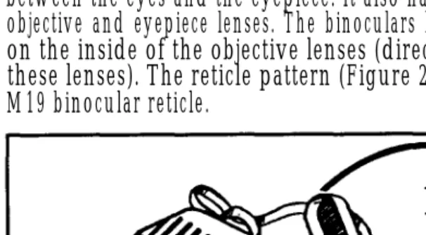
The M22 binoculars (Figure 2-33) can be used instead of the M19. These binoculars have the same features as the M19, plus fold-down eyepiece cups for personnel who wear glasses to reduce the distance between the eyes and the eyepiece. It also has protective covers for the objective and eyepiece lenses. The binoculars have laser protection filters on the inside of the objective lenses (direct sunlight can reflect off these lenses). The reticle pattern (Figure 2-33) is different than the M19 binocular reticle.
2-17. OTHER SNIPER EQUIPMENT
Other equipment the sniper needs to complete a successful mission follows:
a. Sidearms. Each member of the team should have a sidearm, such as an M9, 9-mm Beretta, or a caliber .45 pistol. A sidearm gives a sniper the needed protection from a nearby threat while on the ground moving or while in the confines of a sniper position.
b. Compass. Each member of the sniper team must have a lensatic compass for land navigation.
c. Maps. The team must have military maps of their area of operations.
[image:56.608.30.333.164.331.2]e. Rucksack. The sniper’s rucksack should contain at least a two-quart canteen, an entrenching tool, a first-aid kit, pruning shears, a sewing kit with canvas needles and nylon thread, spare netting and garnish, rations, and personal items as needed. The sniper also carries his ghillie suit (Chapter 4, paragraph 4-4) in his rucksack until the mission requires its use.
f. Measuring Tape. A standard 10-foot to 25-foot metal carpenter’s tape allows the sniper to measure items in his operational area. This information is recorded in the sniper data book. (See Chapter 4 for range estimation.)
Section V
COMMUNICATIONS EQUIPMENT
The sniper team must have a man-portable radio that gives the team secure communications with the units involved in their mission.
2-18. AN/PRC-77 RADIO
2-19. AN/PRC-104A RADIO TRANSCEIVER
The AN/PRC-104A is a state-of-the-am lightweight radio transceiver that operates in the high frequency and in the upper part of the low frequency portions of the radio spectrum (Figure 2-35). The receiver/transmitter circuits can be tuned to any frequency between 2.0000 and 29.9999 MHz in 100 Hz increments, making it possible to tune up to 280,000 separate frequencies. The radio operates in the upper or lower side bank modes for voice communications, CW for Morse code, or FSK (frequency-shift keying) for transmission of teletype or other data.
2-20. AN/PRC-119 RADIO
CHAPTER 3
MARKSMANSHIP
Sniper marksmanship is an extension of basic rifle marksmanship and focuses on the techniques needed to engage targets at extended ranges. To successfully engage targets at increased distances, the sniper team must be proficient in marksmanship fundamentals and advanced marksmanship skills. Examples of these skills are determining the effects of weather conditions on ballistics, holding off for elevation and windage, engaging moving targets, using and adjusting scopes, and zeroing procedures. Markmanship skills should be practiced often.
Section I FUNDAMENTALS
The sniper team must be thoroughly trained in the fundamentals of marksmanship. These include assuming a position, aiming, breath control, and trigger control. These fundamentals develop fixed and correct firing habits for instinctive application. Every sniper should periodically refamiliarize himself with these fundamentals regardless of his experience.
3-1. STEADY POSITION ELEMENTS
The sniper should assume a good firing position (Figure 3-1, page 3-2) in order to engage targets with any consistency. A good position enables the sniper to relax and concentrate when preparing to fire.
a. Position Elements. Establishing a mental checklist of steady position elements enhances the sniper’s ability to achieve a first-round hit.
to lower the weapon’s butt. An effective method is to hold a sock full of sand in the nonfiring hand and to place the weapon butt on the sock. This reduces body contact with the weapon. To raise the butt, squeeze the sock and to lower it, loosen the grip on the sock.
(2) Butt of the stock. Place the butt of the stock firmly in the pocket of the shoulder. Insert a pad on the ghillie suit (see Chapter 4) where contact with the butt is made to reduce the effects of pulse beat and breathing, which can be transmitted to the weapon.
(3) Firing hand. With the firing hand, grip the small of the stock. Using the middle through little fingers, exert a slight rearward pull to keep the butt of the weapon firmly in the pocket of the shoulder. Place the thumb over the top of the small of the stock. Place the index finger on the trigger, ensuring it does not touch the stock of the weapon. This avoids disturbing the lay of the rifle when the trigger is squeezed.
(4) Elbows. Find a comfortable position that provides the greatest support.
(5) Stock weld. Place the cheek in the same place on the stock with each shot. A change in stock weld tends to cause poor sight alignment, reducing accuracy.
(7) Muscle relaxation. When using bone support, the sniper can relax muscles, reducing any movement that could be caused by tense or trembling muscles. Aside from tension in the trigger finger and firing hand, any use of the muscle generates movement of the sniper’s cross hairs.
(8) Natural point of aim. The point at which the rifle naturally rest in relation to the aiming point is called natural point of aim.
(a) Once the sniper is in position and aimed in on his target, the method for checking for natural point of aim is for the sniper to close his eyes, take a couple of breaths, and relax as much as possible. Upon opening his eyes, the scope’s cross hairs should be positioned at the sniper’s preferred aiming point. Since the rifle becomes an extension of the sniper’s body, it is necessary to adjust the position of the body until the rifle points naturally at the preferred aiming point on the target.
(b) Once the natural point of aim has been determined, the sniper must maintain his position to the target. To maintain his natural point of aim in all shooting positions, the natural point of aim can be readjusted and checked periodically.
(c) The sniper can change the elevation of the natural point of aim by leaving his elbows in place and by sliding his body forward or rearward. This raises or lowers the muzzle of the weapon, respectively. To maintain the natural point of aim after the weapon has been fired, proper bolt operation becomes critical. The sniper must practice reloading while in the prone position without removing the butt of the weapon from the firing shoulder. This may be difficult for the left-hand firer. The two techniques for accomplishing this task are as follows:
After firing, move the bolt slowly to the rear while canting the weapon to the right. Execution of this task causes the spent cartridge to fall next to the weapon.
After firing, move the bolt to the rear with the thumb of the firing hand. Using the index and middle fingers, reach into the receiver and catch the spent cartridge as it is being ejected. This technique does not require canting the weapon.
NOTE: The sniper conducts bolt operation under a veil or equivalent camouflage to improve concealment.
the sniper can use many variations of the basic positions. When assuming a firing position, he must adhere to the following basic rules:
(1) Use any support available.
(2) Avoid touching the support with the barrel of the weapon since it interferes with barrel harmonics and reduces accuracy.
(3) Use a cushion between the weapon and the support to prevent slippage of the weapon.
(4) Use the prone supported position whenever possible.
c. Types of Firing Positions. Due to the importance of delivering precision fire, the sniper makes maximum use of artificial support and eliminates any variable that may prevent adhering to the basic rules. He uses the prone supported; prone unsupported; kneeling unsupported; kneeling, sling supported; standing supported; and the Hawkins firing positions.
(1) Prone supported position. The prone supported position is the steadiest position; it should be used whenever possible (Figure 3-2). To assume the prone supported position, the sniper should—
(a) Lie down and place the weapon on a support that allows pointing in the direction of the target. Keep the position as low as possible. (For field-expedient weapon supports, see paragraph 3-1d.)
(c) Keep the body in line with the weapon as much as possible-not at an angle. This presents less of a target to the enemy and more body mass to absorb recoil.
(d) Spread legs a comfortable distance apart with the heels on the ground or as close as possible without causing strain.
(2) Prone unsupported position. The prone unsupported position (Figure 3-3) offers another stable firing platform for engaging targets. To assume this position, the sniper faces his target, spreads his feet a comfortable distance apart, and drops to his knees. Using the butt of the rifle as a pivot, the firer rolls onto his nonfiring side. He places the rifle butt in the pocket formed by the firing shoulder, grasps the pistol grip in his firing hand, and lowers the firing elbow to the ground. The rifle rests in the V formed by the thumb and fingers of the nonfiring hand The sniper adjusts the position of his firing elbow until his shoulders are about level, and pulls back firmly on the rifle with both hands. To complete the position, he obtains a stock weld and relaxes, keeping his heels close to the ground.
(3) Kneeling unsupported position. The kneeling unsupported position (Figure 3-4, page 3-6) is assumed quickly. It places the sniper high enough to see over small brush and provides for a stable position.
(c) Keep the left leg as perpendicular to the ground as possible; sit back on the right heel, placing it as directly under the spinal column as possible. A variation is to turn the toe inward and sit squarely on the right foot.
(d) Grasp the small of the stock of the weapon with the firing hand, and cradle the fore-end of the weapon in a crook formed with the left arm. (e) Place the butt of the weapon in the pocket of the shoulder, then place the meaty underside of the left elbow on top of the left knee.
(f) Reach under the weapon with the left hand, and lightly grasp the firing arm.
(g) Relax forward and into the support position, using the left shoulder as a contact point. This reduces transmission of the pulsebeat into the sight picture.
-(h) Lean against a tree, building, or vehicle for body support.
(a) Place the left arm (nonfiring) through the loop; pull the sling up the arm and place it on the upper arm between the elbow and shoulder, but not directly over the biceps.
(b) Tighten the sling by sliding the sling keeper against the loop holding the arm.
(c) Rotate the left arm in a clockwise motion around the sling and under the rifle with the sling secured to the upper arm. Place the fore-end of the stock in the V formed by the thumb and forefinger of the left hand. Relax the left arm and hand, let the sling support the weight of the weapon. (d) Place the butt of the rifle against the right shoulder and place the left elbow on top of the left knee (Figure 3-5). Pull the left hand back along the fore-end of the rifle toward the trigger guard to add to stability.
(5) Standing supported position. The standing supported position is the least steady of the supported positions and should be used only as a last resort (Figure 3-6, page 3-8).
(a) To assume the standing supported position with horizontal support, such as a wall or ledge, the sniper proceeds as follows:
Form a V with the thumb and forefinger of the nonfiring hand. Place the nonfiring hand against the support with the fore-end of the weapon resting in the V of the hand. This steadies the weapon and allows quick recovery from recoil.
(b) To use vertical support (Figure 3-7), such as a tree, telephone pole, comer of building, or vehicle, the sniper proceeds as follows:
Locate stable support. Face the target, then turn 45 degrees to the right of the target, and place the palm of the nonfiring hand at arm’s length against the support.
Lock the left arm straight, let the left leg buckle, and place body weight against the nonfiring hand. Keep the trail leg straight. Place the fore-end of the weapon in the V formed by extending the thumb of the nonfiring hand.
(6) Hawkins position. The Hawkins position (Figure 3-8) is a variation of the prone unsupported position. The sniper uses it when firing from a low bank or a depression in the ground, over a roof, or so forth. It cannot be used on level ground since the muzzle cannot be raised high enough to aim at the target. It is a low-profile position with excellent stability and aids concealment. To assume this position, the sniper uses the weapon’s sling and proceeds as follows:
CAUTION
LOCK THE NONFIRING ARM STRAIGHT OR THE FACE WILL ABSORB THE WEAPON’S RECOIL.
(a) After assuming a prone position, grasp the upper sling swivel and sling with the nonfiring hand, forming a fist to support the front of the weapon.
(b) Ensure the nonfiring arm is locked straight since it will absorb the weapon’s recoil. Wearing a glove is advisable.
(c) Rest the butt of the weapon on the ground and place it under the firing shoulder.
d. Field-Expedient Weapon Support. Support of the weapon is critical to the sniper’s success in engaging targets. Unlike a well-equipped firing range with sandbags for weapon support, the sniper can encounter situations where weapon support relies on common sense and imagination. The sniper should practice using these supports at every opportunity and select the one that best suits his needs. He must train as if in combat to avoid confusion and self-doubt. The following items are commonly used as field-expedient weapon supports
(1) Sand sock. The sniper needs the sand sock when delivering precision fire at long ranges. He uses a standard issue, olive-drab wool sock filled one-half to
three-quarters full of sand and knotted off. He places it under the rear sling swivel when in the prone supported position for added stability (Figure 3-9). By limiting minor movement and reducing pulse beat, the sniper can concentrate on trigger control and aiming. He uses the
nonfiring hand to grip the sand sock, rather than the rear sling swivel. The sniper makes minor changes in muzzle elevation by squeezing or relaxing his grip on the sock. He uses the sand sock as padding between the weapon and a rigid support also.
(3) Sandbag. The sniper can fill an empty sandbag (Figure 3-11) on site.
(4) Tripod. The sniper can build a field-expedient tripod (Figure 3-12) by tying together three 12-inch long sticks (one thicker than the others) with 550 cord or the equivalent. When tying the sticks, he wraps the cord at the center point and leaves enough slack to fold the legs out into a triangular base. Then, he places the fore-end of the weapon between the three uprights.
(5) Bipod. The sniper can build a field-expedient bipod (Figure 3-12) by tying together two 12-inch sticks, thick enough to support the weight of the weapon. Using 550 cord or the equivalent, he ties the sticks at the center point, leaving enough slack to fold them out in a scissor-like manner. He then places the weapon between the two uprights. The bipod is not as stable as other field-expedient items, and it should be used only in the absence of other techniques.
e. Sniper and Observer Positioning. The sniper should find a place on the ground that allows him to build a steady, comfortable position with the best cover, concealment, and visibility of the target area. Once established, the observer should position himself out of the sniper’s field of view on his firing side.
(1) The closer the observer gets his spotting telescope to the sniper’s line of bore, the easier it is to follow the trace (path) of the bullet and observe the point of impact. A position at 4 to 5 o’clock (7 to 8 o’clock for left-handed firers) from the firing shoulder and close to (but not touching) the sniper is best (Figure 3-13).
(2) If the sniper is without weapon support in his position, he uses the observer’s body as a support (Figure 3-14). This support is not recommended since the sniper must contend with his own movement and the observer’s body movement. The sniper should practice and prepare to use an observer supported position. A variety of positions can be used; however, the two most stable are when the observer is in a prone or sitting position.
(a) Prone. To assume the prone position, the observer lies at a 45-to 75-degree angle to the target and observes the area through his spotting telescope. The sniper assumes a a prone supported position, using the back of the observer’s thigh for support. Due to the offset angle, the observer may only see the bullet impact.
3-2. AIMING
e. Sight Picture. With telescopic sights, the sight picture is the relationship between the reticle and full field of view and the target as seen by the sniper. The sniper centers the reticle in a full field of view. He then places the reticle center of the largest visible mass of the target (as in iron sights). The center of mass of the target is easiest for the sniper to locate, and it surrounds the intended point of impact with a maximum amount of target area. With iron sights, sight picture is the relationship between the rear aperture, the front sight blade, and the target as seen by the sniper (Figure 3-18). The sniper centers the top edge of the blade in the rear aperture. He then places the top edge of the blade in the center of the largest visible mass of the target (disregard the head and use the center of the torso).