© 2019, IRJET | Impact Factor value: 7.211 | ISO 9001:2008 Certified Journal
| Page 7015
Numerical Investigation of Heat Performance Enhancement for a
Double-Pipe Heat Exchanger at Annulus with Continuous Helical
Baffles using Al
2O
3as Nanofluid
Amit Kumar Singh
1, H.C.Thakur
21,2
Department of Mechanical Engineering, Gautam Buddha University, Greater Noida,, India
---***---
Abstract -Main goal of our project is to maximize the heat transfer rate and minimizing the pressure drop as much as possible to increase the performance enhancement factor for heat exchanger. As we know that by increasing Reynolds number Nusselt number increases thus increasing the heat transfer rate but in doing so pressure drop is also increased that is not beneficial for the operating of heat exchanger so we used passive technique that is the use of nanofluid in place of water as cold fluid in the annulus side to increase heat transfer rate. In this project we keep the mass flow at 0.1, 0.15, 0.2, 0.25, 0.3 Kg/s. AL2O3 is used as nanofluid with volumetric concentration of 1%, 2%, 3%, 4% respectively and found that heat transfer rate is increased while there is a decrement in pressure drop. And we have also plotted the graph for heat transfer, pressure drop and performance enhancement factor
Key Words: Continuous helical baffles, Water to water heat exchanger, Heat transfer enhancement, Double pipe, Friction,
Numerical
1. INTRODUCTION
Double-pipe exchanger is made of two pairs of pipes that are concentric to each other. There can be same or two different fluids that are transferring heat from inner to outer pipes or vice versa. The fluids usually flow in counter clockwise directions. They are mostly used in applications involving relatively low flow rates and high temperatures or pressures. Other advantages include low installation cost, ease of maintenance, and flexibility.
One of the starting studies performed on double pipe heat exchangers was done by Mozley [1] who numerically and experimentally developed a case to study various dynamic characteristics of a special DPHEs. Those were derived from simple mathematical models. From this research frequency responses was studied it matched experimental results. Research has been done to increase the heat transfer rate of heat exchangers which helps in saving energy, money and time. It also helps in increasing thermal rating and extending the overall working life of the device. This is done by using various passive geometrical features to increase the heat transfer capacity. These innovations reduces the thermal resistance but increasing the pressure drop , as reported by Jian et al. [2] Bhadouriya et al. [3].
In this study, Rennie and Raghavan [4] studied DPHE. The study was conducted using both parallel and counter flow arrangements. During research it was concluded that performance evaluation criterion was identical for both configurations, also there was a huge difference in the heat transfer to the counter flow configuration due to its high temperature difference as compared to its counterpart Wilson plots were used to determine the heat transfer rates of inner tube and the annulus.
In this research Bhadouriya et al. [5] studied DPHE both experimentally and numerically. The objective was to research on the heat transfer and pressure drop. Boundary condition of annulus wall was taken as uniform temperature wall for outer flow. The important point of the study was to research the effect of twist ratio of the inner tube on the flow characteristics. Air and water were taken as the working fluid in the outer and inner tube of the heat exchanger, respectively.
Following the pervious researches, in another experimental investigation, Yadav [6] investigated the effects of half-length twisted tapes on heat transfer and pressure drop of a double pipe U-bend heat exchanger. The twisted tapes were in the inner tube of a DPHE which caused a 40-percent increase in heat transfer in comparison with smooth tube
Prasad et al. [7] studied the effect of trapezoidal-cut twisted tapes in a DPHE. The nanofluid used in this investigation was water-based Al2O3 which was in turbulent flow regime. The results showed that the heat transfer rate increase in the annulus was higher than that of the inner tube which this was mainly due to the secondary flows in the annulus. They also observed that the increase in nanofluid concentration and also the twist ratio leads to a higher heat transfer and pressure drop. Heat transfer performance of a double pipe heat exchanger at annulus side with continuous helical baffles was studied by Maakoul et al.[8] numerically The research was conducted for different mass flow rate (0.1 -0.3 kg/s) and baffle spacing (0.025–0.1 m). The results showed an increase in heat transfer and pressure drop as compared to
© 2019, IRJET | Impact Factor value: 7.211 | ISO 9001:2008 Certified Journal
| Page 7016
Nomenclature
Latin symbols u average velocity, m/s
Across cross-flow area at the annulus side, m2 x; y; z Cartesian coordinate
B baffle spacing, mm
cp specific heat capacity, J/(kg K) Greek symbols
ci coefficients in k e model Γ generalized diffusion coefficient
Ds internal annulus diameter, m ε turbulent kinetic energy dissipation rate, m2/s3
Do external tube diameter, m k thermal conductivity, W/(m K)
Dh hydraulic diameter, m μ dynamic viscosity, kg/(m s)
h average heat transfer coefficient, W/(m2 K) ν kinematic viscosity, m2/s
k turbulent fluctuation kinetic energy, m2/s2 q density, kg/m3
L tube total effective length, m σk Prandtl number for k
f friction factor σε Prandtl number for ε
m mass flow rate, kg/s ϕ nanoparticle volume fraction
Pr Prandtl number
Subscripts
∆p pressure drop, Pa
in inlet
Q heat transfer rate, W
out outlet
Re Reynolds number
a annulus side
Nu Nusselt number
t tube side
Tin hot water inlet temperature, oC
turb turbulent
tin cold water inlet temperature, oC
2. NUMERICAL MODEL
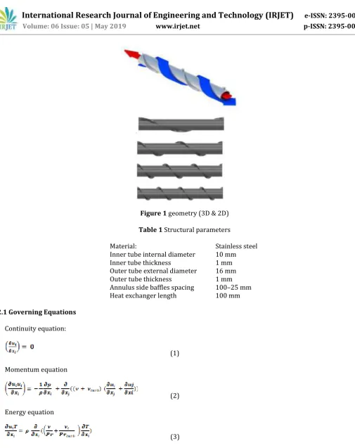
The main goal of this paper is to study heat transfer performance for double-pipe heat exchanger at annulus side with continuous baffle of different spacing. This leads to change in the heat transfer, pressure drop, velocity in the annulus flow domain and thus the net heat transfer rate and pressure drop varies from initial values. This structure is made of steel to facilitate better heat transfer and resistance to corrosion. The D structure is shown in fig 1the baffle spacing is varied between 100mm to 0.25 mm and the heat performance of the structure is analyzed using water and nanofluid. Even though it seems that the structure is simple but when analyzing the fluid flow it becomes complex due to introduction of baffles on annulus side.
© 2019, IRJET | Impact Factor value: 7.211 | ISO 9001:2008 Certified Journal
| Page 7017
[image:3.595.40.546.34.672.2]Figure 1 geometry (3D & 2D)
Table 1 Structural parameters
Material: Stainless steel
Inner tube internal diameter 10 mm
Inner tube thickness 1 mm
Outer tube external diameter 16 mm
Outer tube thickness 1 mm
Annulus side baffles spacing 100–25 mm Heat exchanger length 100 mm
2.1 Governing Equations
Continuity equation:
(1)
Momentum equation
(2)
Energy equation
(3)
To solve the problem that arises by turbulent flow which was caused by the introduction of baffle spacing on annulus side Realizable k e turbulence model was selected in energy. The equations for realizable k e model are given below:
Turbulent kinetic energy k equation:
© 2019, IRJET | Impact Factor value: 7.211 | ISO 9001:2008 Certified Journal
| Page 7018
Turbulent energy dissipation equation
(5)
where C represents the generation of turbulence kinetic energy k due to the mean velocity gradients The wall is set to scalable wall function
2.2 Domains definitions, mesh sensitivity and boundary conditions
At geometry creation we have to make a straight double pipe heat exchanger with continuous baffle on annulus side. First we have to draw a circle of Dia 10mm and then another concentric circle of Dia 12mm at the center the select both the sketch and click generate surface. Similarly from the center point draw another sketch of two circle of Dia 16mm and 17mm. again select the second sketch and click on generate surface. After this draw a new sketch that are two straight line between inner tube outer circumference and outer tube inner circumference also the distance of both straight line from axis is 0.5mm on both side. Again select this sketch and click on generate surface. Now select the first two sketches and select extrude. In this select direction as both forward and backward with extrude length of 50mm. Now separately select the third sketch and select revolve in the pitch section select the pitch according to the baffle spacing. Then select direction as forward and backward. Also select the axis that is passing through the center of the circle around which the helical baffle will be rotated.
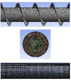
[image:4.595.235.359.583.725.2]Meshing is done in the mesh window. In this portion a mix of unstructured tetrahedral and wedge (Prism) grid is used. Inflation option is used near the wall of tubes
Table 2 Mesh quality
The no slip condition for all the solid walls
The software FLUENT is used to calculate the fluid flow and heat transfer in the computational domains. The governing equations are iteratively solved by the finite-volume formulation with the SIMPLE algorithm. The second-order upwind scheme is adopted for the momentum, energy, turbulence and its dissipation rate. The pressure term is treated with the standard scheme.
Outer wall is considered as insulated wall. In this condition heat is transferred from hot fluid to cold fluid through a solid steel wall that is the inner wall of heat exchanger and cold fluid gets warmer and hot fluid gets colder. For inlet of hot fluid was set as velocity inlet. Here the velocity of inlet is kept constant at 0.1kg/s mass flow rate throughout the entire analysis. The inlet temperature of the hot fluid was taken as 312K. Similarly for inlet of cold fluid was set as velocity inlet. Here the velocity of inlet was varied by changing the mass flow rate. The mass flow rate of the working fluid was varied between 0.1, 0.15, 0.2, 0.25, 0.3 kg/s. The inlet temperature of cold fluid was taken as 288K. For the outlet of cold fluid and hot fluid was takes as Pressure outlet boundary condition.
Nodes Elements Average skewness Average orthogonal quality
© 2019, IRJET | Impact Factor value: 7.211 | ISO 9001:2008 Certified Journal
| Page 7019
At the outlet the gauge pressure was taken as zero atmospheric pressure. The wall of the outer tube is taken as insulted wall condition, this done because there is no heat exchange taking place through that wall The fluid property of water was assumed to be continuous throughout the analysis with respect to temperature.
3. DATA REDUCTION
3.1 Annulus side velocity
ua= ma/(ρaAcross) (6)
3.2 Characteristics cross section area for helically baffle annulus side
Across= 0.5B(Ds - Do) (7)
With the mean velocity value, the Reynolds number for the annulus side is determined by: Re= (ρauaDo)/μ (8)
3.3 Heat transfer rate:
Heat transfer rate of the annulus side fluid (cool water): Qa= maCpa(Tout a-Tin a) (9)
Heat transfer for hot fluid tube
Qt=mtCpt(Tin t-Tout t) (10)
3.4 Nusselt number
Nu = (haDh)/k (11)
When using nanofluid in place of water
3.5 Thermal conductivity:
For calculating thermal conductivity of water based Nanofluid Maxwell [9] formula is used. Also Brownian effect is neglected. The effective thermal conductivity of nanofluid is given by:
(12)
3.6 Specific heat and density:
Calculation of specific heat and density is straight forward. They can be based on the physical guideline of the blend administer these outcomes are in great understanding with experiment information. The specific heat is formula [9]:
(Cp)nf = (1-ϕ)(Cp)f + ϕ(Cp)np (13)
3.7 Density is calculated by using formula given by[9]
ρnf = (1-ϕ)ρf + ϕρnp (14)
3.9 Viscosity
μnf = μf(1+2.5ϕ) (15)
4. RESULTS AND DISCUSSION
© 2019, IRJET | Impact Factor value: 7.211 | ISO 9001:2008 Certified Journal
| Page 7020
4.1 Fluid flow characteristics
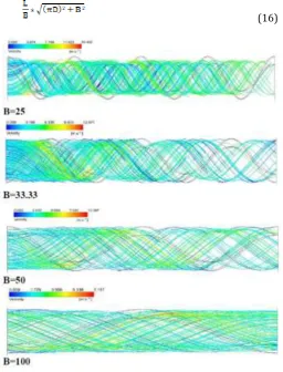
In Fig. 3 velocity streamline simulation has been shown. It can be seen that the max velocity is at the inlet of the fluid. It can also be seen that due to introduction of continuous helical baffle on annulus side, helical flow is initiated. Due to helical path the same length of double pipe exchanger provides a greater flow path for the fluid hence increasing the heat transfer effect. This leads more compact exchanger design. Also due to helical path the turbulence of the fluid is increased which is beneficial in energy transfer. From analyzing the fig 3 it can be seen that the velocity is directly proportional to mass flow rate but inversely proportional to the baffle spacing. The total flow path length can be determined by following formulae
[image:6.595.170.427.205.542.2](16)
Figure 3 Annulus side velocity streamlines at m= 0:3 kg/s for different baffle spacing when using water as fluid
The velocity is at max at the inlet of the annulus this can be explained by the fact that there is a sudden decrease in the cross section area. Hence the velocity can only be increased to maintain the same mass flow rate at the annulus side. This can be used to explain the sudden rise in velocity when increasing the mass flow rate at the annulus side.
4.2 Heat transfer performance
© 2019, IRJET | Impact Factor value: 7.211 | ISO 9001:2008 Certified Journal
| Page 7021
Figure 4(A)
Figure 4(B)
Figure 4(C)
[image:7.595.186.400.57.718.2]© 2019, IRJET | Impact Factor value: 7.211 | ISO 9001:2008 Certified Journal
| Page 7022
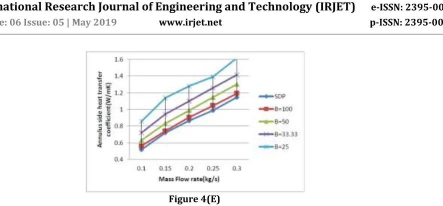
Figure 4(E)
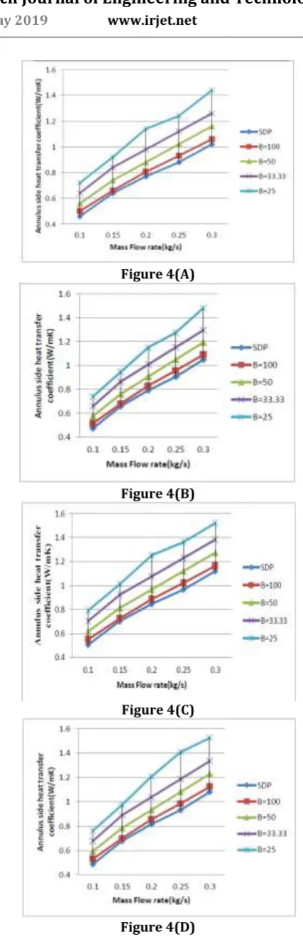
Figure 4(A)(B)(C)(D)(E). Annulus side heat transfer coefficient (*104) w.r.t. mass flow rate for different baffle spacing
Fig.4 (B), (C), (D), (E) demonstrate the heat transfer coefficient results for the annulus side with same condition of baffle spacing and mass flow rate as used in base paper [8]. But the difference is that in this case Al2O3 nanofluid of concentration from 1% to 4% respectively is used. The results from the graph shows that there is an average increase in 2.88%, 5.90%, 9.83% and 12.21% for volumetric concentration of 1%, 2%, 3% and 4% of nanoparticle respectively. The increase in heat transfer can be explained by the fact that with the addition of nanoparticle increases the overall thermal conductivity of base fluid and enhancing the heat transfer results. Also from the graph it can be interpreted that the heat transfer coefficient rate is directly proportional to mass flow rate and inversely proportional to baffle spacing as smaller the baffle spacing greater is the flow path and hence greater is the heat transfer.
4.3 Nusselt number
From Fig. 5(A) results for the base paper [8] validation is shown. From graph it can be seen that results almost matches the graph drawn in the base paper. In this the Nusselt number in the form of NuPr-1/3 at the annulus side is shown foe different baffle spacing as well as for simple double pipe heat exchanger. Results obtained showed the benefits of having continuous baffle spacing on annulus side as compared to simple double pipe heat exchanger.
Figure 5(A)
[image:8.595.103.546.49.255.2] [image:8.595.55.554.469.790.2] [image:8.595.193.450.471.770.2]© 2019, IRJET | Impact Factor value: 7.211 | ISO 9001:2008 Certified Journal
| Page 7023
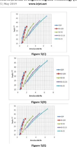
Figure 5(C)
Figure 5(D)
Figure 5(E)
Figure 5(A)(B)(C)(D)(E). Annulus side Nusselt number w.r.t. Reynolds number (*104) for different baffle spacing
From this it can be seen that with increasing mass flow rate and decreasing baffle spacing heat transfer of the heat exchanger increases.
NuPr-1/3 = 0.04572Re0.6098(1+B)7.565 (17)
From equation 17 it can be seen that the value of NuPr-1/3 is inversely proportional to dynamic viscosity which increases with increasing the nanoparticle concentration hence with increasing nanofluid concentration the value for NuPr-1/3 begins to decrease. The results from the fig 5(B), (C), (D), (E) shows that there is an average decrease of 1.49%, 3.22%, 4.31% and 5.64% for volumetric concentration of 1%, 2%, 3% and 4% of nanoparticle respectively.
4.4 Pressure drop
[image:9.595.161.432.58.572.2]© 2019, IRJET | Impact Factor value: 7.211 | ISO 9001:2008 Certified Journal
| Page 7024
hence it is most important to reduce the net pressure drop for the heat exchanger so that it can be most efficient. When the continuous baffle was provided at the annulus side the pressure drop was increased due to following reasons
Fluid flow path was increased
Due to sudden reduction in cross sectional area to maintain the mass flow rate, fluid velocity has to increase.
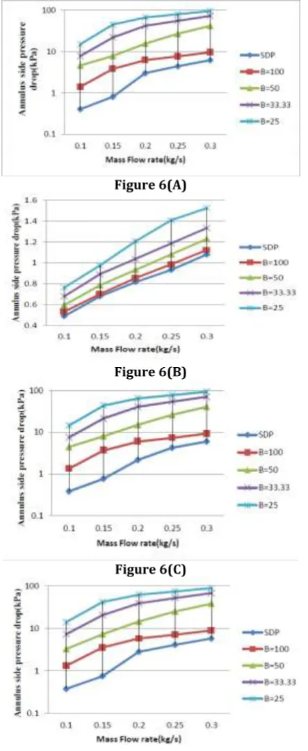
Figure 6(A)
Figure 6(B)
Figure 6(C)
[image:10.595.189.411.171.712.2]© 2019, IRJET | Impact Factor value: 7.211 | ISO 9001:2008 Certified Journal
| Page 7025
Figure 6(E)
Figure 6(A)(B)(C)(D)(E). Annulus side pressure drop w.r.t. mass flow rate for different baffle spacing
In fig 6(A) results from base paper [8] is validated. It can be seen from the graph that pressure drop directly depends on the mass flow rate. Also as baffle spacing is decreased the flow path length increase to maintain the overall fluid flow till the end, pressure has to be increased. Hence pressure drop is inversely proportional to the baffle spacing.
(18)
Fig 6 (B), (C), (D), (E) demonstrates the pressure drop in the outer tube flow region. In these cases Al2O3 nanofluid of concentration from 1% to 4% respectively is used. The results from the graph shows that there is an average decrease of 2.29%, 4.58%, 6.69% and 8.60% for volumetric concentration of 1%, 2%, 3% and 4% of nanoparticle respectively. The decrease in pressure drop can be explained by the fact that it is directly proportional to friction factor and inversely proportional to density of fluid. With the addition of nanoparticle both friction factor and density increase but the increase of density is greater as compared to friction factor. Hence the values of pressure drop on annulus side decreases with increment in the nanoparticle concentration.
4.5 Thermal performance enhancement factor
In earlier times researchers mainly focused on increasing heat transfer irrespective of pumping power loss. This approach is good when the size and pumping power requirement of heat exchanger are considered secondary when comparing it to heat transfer.
[image:11.595.135.459.53.238.2] [image:11.595.176.421.528.682.2]© 2019, IRJET | Impact Factor value: 7.211 | ISO 9001:2008 Certified Journal
| Page 7026
Figure 7(B)
Figure 7(C)
Figure 7(D)
Figure 7(E)
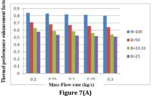
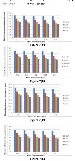
Figure 7(A)(B)(C)(D)(E). Thermal performance enhancement factor w.r.t. mass flow rate for various baffle spacing
But in this paper research is done on those types of heat exchangers that are used in small machinery with low pumping power. Hence we cannot rely on only increasing heat transfer and neglecting pressure drop. So after analyzing the problem a new term was introduced which was called as thermal performance enhancement factor, represented by symbol η. It is the comparison between Nusselt number and pressure drop of annulus side with baffles to Nusselt number of ordinary double pipe heat exchanger without any modifications. This quantity is given by:
[image:12.595.167.429.59.621.2]© 2019, IRJET | Impact Factor value: 7.211 | ISO 9001:2008 Certified Journal
| Page 7027
In Fig. 7(A) results from base paper [8] is validated. It can be seen from the graph that thermal performance enhancement factor is directly proportional to baffle spacing. Also it decreases with the increasing mass flow rate.
This result can be explained by the fact that when the baffle spacing is decreased the pressure drop is tremendously increased as compared to increment in Nusselt number this leads to decrement in the thermal performance enhancement factor, this result is similar to base paper.
From fig 7 (B), (C), (D), (E) When the nanofluid is used the average percentage of change in thermal performance enhancement factor are 0.97%, 0.96%, 0.94% and 0.93% for volumetric concentration of 1%, 2%, 3% and 4% of nanoparticle respectively.
5 CONCLUSIONS
A numerical study has been carried out for tube and tube heat exchanger with continuous helical baffle on annulus side subjected to different boundary conditions. Heat transfer coefficient, product of Nusselt number and Prandtl number, pressure drop, thermal enhancement factor with respect to mass flow rate for different baffle spacing is plotted. Following observations has been noticed-
Increasing the mass flow rate increases the heat transfer coefficient on annulus side.
With decreasing the baffle spacing heat transfer coefficient is increased.
Increasing the mass flow rate increases the pressure drop on annulus side.
With decreasing the baffle spacing pressure drop is exponentially increased
The product of Nusselt number and Prandtl number increases with decreasing baffle spacing and increasing mass flow rate.
Overall the thermal enhancement factor for the mass flow rate of 0.3 kg/s and baffle spacing of 33.33mm is the most balanced of all the results.
When Al2O3 nanofluid is used on annulus side with different boundary conditions following observations has been noticed-
As the concentration of nanofluid is increased the thermal conductivity of the nanofluid is enhanced hence the heat transfer coefficient is also increased. The effect of mass flow rate and baffle spacing remains the same as when water is used in annulus tube.
Pressure drop is directly proportional to friction factor but inversely proportional to density of nanofluid hence when comparing at the same mass flow rate as used in the base paper [8] the pressure drop decreases with increasing volumetric concentration of the nanofluid because the increase of density is greater as compared to friction factor.
REFERENCES
[1] J. Mozley, Predicting dynamics of concentric pipe heat exchangers, Ind. Eng. Chem. 48 (1956) 1035–1041.
[2] Jian W, Huizhu Y, Wang S, Xu S, Yulan X, Tuo H. Numerical investigation on baffle configuration improvement of the heat
exchanger with helical baffles. Energy Conversion and Management (2015); 89: 438–48..
[3] Bhadouriya R, Agrawal A, Prabhu SV. Experimental and numerical study of fluid flow and heat transfer in an annulus of
inner twisted square duct and outer circular pipe. International Journal of Thermal Sciences (2015); 94:96–109.
[4] T.J. Rennie, V.G. Raghavan, Experimental studies of a double-pipe helical heat exchanger, Exp. Thermal Fluid Sci. 29 (2005)
919–924.
[5] R. Bhadouriya, A. Agrawal, S. Prabhu, Experimental and numerical study of fluid flow and heat transfer in an annulus of
inner twisted square duct and outer circular pipe, Int. J. Therm. Sci. 94 (2015) 96–109.
[6] A.S. Yadav, Effect of half length twisted-tape turbulators on heat transfer and pressure drop characteristics inside a double
pipe u-bend heat exchanger, JJMIE 3 (2009).
[7] P.D. Prasad, A. Gupta, K. Deepak, Investigation of trapezoidal-cut twisted tape insert in a double pipe U-tube heat exchanger
using Al2O3/water nanofluid, Procedia Mater. Sci. 10 (2015) 50–63.
[8] Anas El Maakoul, Azzeddine Laknizi, Said Saadeddine, Abdellatif Ben Abdellah, Mohamed eziane, Mustapha El Metoui,
Numerical design and investigation of heat transfer enhancement and performance for an annulus with continuous helical baffles in a double-pipe heat exchanger, Energy Conversion and Management (2016), 76-86.
[9] B. Ghasemi, S.M. Aminossadati, Brownian motion of nanoparticles in a triangular enclosure with natural convection,