Accepted Manuscript
Research Paper
Development of microencapsulated phase change material for solar thermal en-ergy storage
Weiguang Su, Jo Darkwa, Georgios Kokogiannakis
PII: S1359-4311(16)32969-6
DOI: http://dx.doi.org/10.1016/j.applthermaleng.2016.11.009
Reference: ATE 9414
To appear in: Applied Thermal Engineering Received Date: 31 August 2016
Revised Date: 23 October 2016 Accepted Date: 1 November 2016
Please cite this article as: W. Su, J. Darkwa, G. Kokogiannakis, Development of microencapsulated phase change material for solar thermal energy storage, Applied Thermal Engineering (2016), doi: http://dx.doi.org/10.1016/ j.applthermaleng.2016.11.009
1
Development of microencapsulated phase change
material for solar thermal energy storage
Weiguang Su1,a, Jo Darkwa2, Georgios Kokogiannakis3
1. School of Mechanical & Automotive Engineering, Qilu University of Technology, Jinan, China
2. Faculty of Engineering, University of Nottingham, UK
3. Sustainable Buildings Research Centre, University of Wollongong, Australia
Nomenclature
, , the specific heat of water, core material and shell material latent heat of PCM
enthalpy
, , the conductivity of water, paraffin and shell material
, , the weight percentage of water, core material and shell material the weight percentages of MEPCM in TES unit
, , the volume percentage of water, shell material and core material
the temperature difference
the core material content of MEPCM
a
2
1
Introduction
3
However, PCMs generally possess low thermal conductivity and hence poor thermal response factor. For example the study by López-Navarro et al. [14] showed a declining thermal response factor in a PCM storage tank after a few number of thermal cycling and was attributed to low thermal conductivity of the PCM. Other general weakness in PCMs is instability in their melting temperatures during long term storage operation. This phenomena was evident in a study by Behzadi [15] when the melting temperature of the PCM shifted from 21 to 28℃ after 120 repeated thermal cycles. Apart from thermal instability issue, Chen et al. [16] also observed a high level of thermal stress in a PCM storage tank as a result of considerable change in density during phase transition period.
4
2
Development of MEPCM
2.1
Material selection
5
2.2
Fabrication of MEPCM
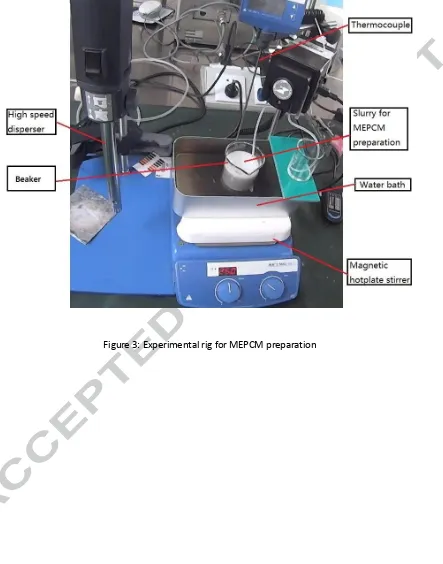
The fabrication of the MEPCM samples was based on in-situ polymerization method as well as processes covering synthesisation of prepolymer solution, preparation of oil-in-water (O/W) emulsion and formation of shells. The value of hydrophilic–lipophilic balance (HLB) [20] of emulsifier is one of the most important factors for preparing a stable oil-in-water (O/W) emulsion. Meanwhile, the average HLB value for the nonionic binary emulsifier can be calculated according to the weight percentages and HLB values of the initial components [21]. Therefore Brij 30 and Brij 58 were mixed together at an appropriate HLB value of 12 to prepare for the O/W emulsion. As shown in Fig. 2, melamine (4.04g) and 37% formaldehyde solution (6.5g) were initially mixed with 10ml deionized water at a stirring speed of 200 rpm. It was then heated up to 70°C and maintained at that reaction temperature until the suspension became transparent. The prepolymer solution was prepared at a pH value of 8.5–9 with 0.2wt% sodium hydroxide solution. The next stage of the fabrication process involved mixing together the molten paraffin with denoized water and the emulsifiers. The solution was then stirred at a speed of 7000rpm for 10min with a dispersion machine (IKA T18, Germany, see Fig.3) to obtain a stable O/W emulsion.
6
rpm with a magnetic stirrer (type IKA HS-7, Germany, see Fig.3) for 4 hours at a temperature of 70°C. The end product was finally filtered, washed with water and then dried in an oven at a temperature of 60°C for 20 hours.
3
Results and analysis
3.1
Evaluation of fabricated MEPCM samples
3.1.1
Scanning electron microscopy (SEM) analysis
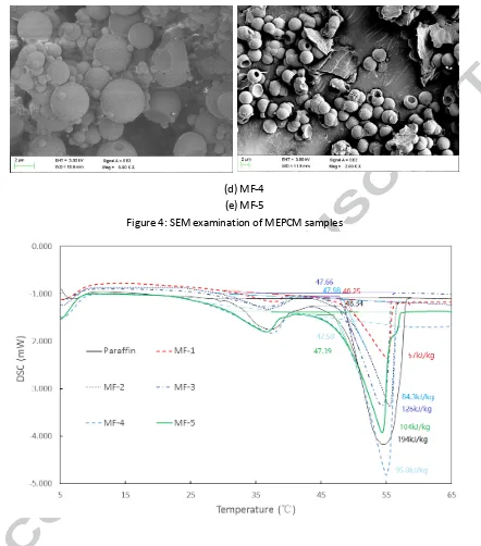
A scanning electron microscope (SEM) by Sigma VP, Carl Zeiss Co. Ltd., was used to examine the morphologies of the fabricated MEPCM samples. Since the shell material is a non-conductive material, the samples were initially coated with 5 nm thick gold layer in order to increase their electrical conductivity before the microscopy analysis was carried out. This procedure was in accordance with a similar study carried out by Suzuki [22].
7
the binary emulsifiers (Brij 30 and Brij 58). In general emulsifiers are used for reducing interfacial tension in O/W emulsions and to prevent coalescence by capsules adsorption onto the oil/water interface in order to promote the formation of regular shapes of capsules during microencapsulation process. It is obvious from the outcomes that the binary emulsifiers were more effective than the SDS emulsifier due to the synergy of the two emulsifiers [23] hence.
3.1.2
Energy storage capacity, melting temperature and encapsulation
efficiency
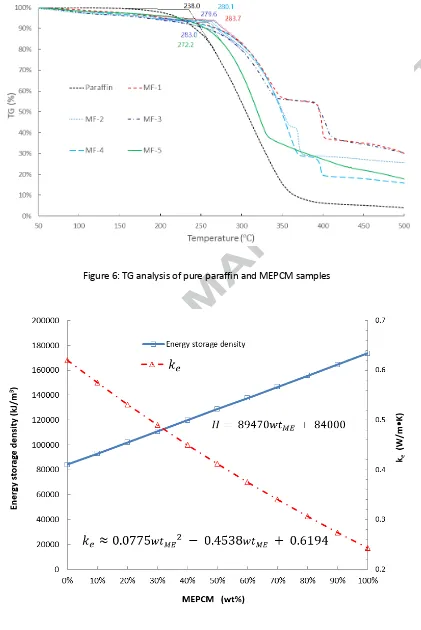
A differential scanning calorimetric (DSC6220, SII Nanotechnology) equipment was used in determining the enthalpies of fusion and melting temperature of the MEPCM samples in accordance with ISO 11357 Standards under the dynamic testing method. The samples were tested at atmospheric pressure and at a heating rate of 2 °C /min from 5℃ to 65℃.
8
core material contents for the samples were therefore obtained as 29% for MF-1, 43% for MF-2, 65% for MF-3 49% for MF-4 and 54% for MF-5. Now based on the initial core/shell weight ratios in Tab. 1, the corresponding encapsulation efficiencies were obtained as 44.23%, 65.18%, 97.42%, 74.07% and 80.41%.
Beside the morphology the type of emulsifiers also demonstrated some effects on the core material content and encapsulation efficiency for the fabricated MEPCM samples. For instance, the core material content for sample MF-4 (49%) was much higher than sample MF-1 (29%) due to the effect of the binary emulsifier. However, comparison of MF-5 and MF-3 shows that the core material content was reduced about 11% by the binary emulsifier, which was attributed to the fact that some of the capsules in MF-5 were not fully encapsulated.
9
3.1.3
Thermal stability
10
heat storage media for the proposed TES unit can be improved by using the developed MEPCM.
3.2
Theoretical evaluation of proposed TES unit
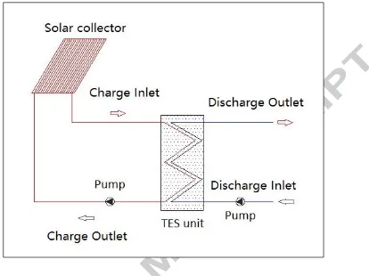
As described in Fig. 1, the TES unit is similar to the concept adopted for enhancing energy storage density and effective thermal conductivity in a study conducted by Darkwa et al. [29]. Therefore by considering individual elements and their weight proportions the various percentages of energy storage capacity may be calculated using Eq. 1 below as:
(1)
(2)
(3)
(4)
So that Eq.1 becomes: (5)
Where
, and are the weight percentages of water, core material and shell material
11
, and are the corresponding specific heat capacities, J/kg∙℃.
, , and are the corresponding densities, kg/m3.
is the latent heat of PCM, kJ/kg.
is the temperature difference, ℃.
is the weight percentages of MEPCM in TES unit, %.
is the core material content of MEPCM, %.
The effective thermal conductivity can also be calculated by considering the conductivity and the volume fraction of each component as established by Thiele et al. [30] and reported by Felske [31] in Eq. 6 as:
(6)
(7)
(8)
12
(9)
By the same method,
(10)
Where
, and are the conductivities of water, paraffin and shell material, W/m∙K.
and are the volume percentages of water, shell material and core material, %.
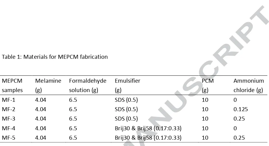
Now using sample MF-3 and the data in Tab. 3, the energy storage density and the effective thermal conductivity of the TES unit over a range of 40 to 60 ℃ with different weight percentage of MPECM can be calculated and represented graphically in Fig. 7.
13
conductivity of (ke1) would reduce to 0.41 W/m∙K, it is still about 2 times that of pure paraffin. In
comparison with other studies, the effective conductivity of the developed MEPCM is much higher than other thermal energy storage materials, such as lauric acid (0.148~0.150 W/m∙K) [10], PCM emulsion (0.27 W/m∙K) [13], RT8 (0.20 W/m∙K) [14] and Rubitherm 21 (0.20 W/m∙K) [15]. Previous investigations also showed that thermal response time of TES units were poor due to low thermal conductivity of the phase change materials. For instance the experimental results by Murray and Groulx [10] showed that the time requirements for thermal energy charging and discharging in a TES system were as long as 30 hours and 32 hours respectively. The thermal response of the proposed TES unit is therefore expected to be much higher during thermal energy charging/discharging cycling. There is however the need for the TES unit to be optimized based on design and operational requirements.
4
Conclusions
14
thermal stability of the samples was relatively high with MF-3 reaching 279.7℃. The encapsulation efficiency was however influenced by the nucleation agent whilst the morphology was also affected by the type of emulsifier since samples MF-4 and MF-5 achieved much better morphology with the binary emulsifier than samples MF-1, MF-2 and MF-3 which were fabricated with SDS emulsifier. In order to assess their thermal effectiveness, MF-3 was theoretically evaluated in an integrated compacted fixed bed unit and found to be capable of contributing to a system with higher energy storage density and relatively smaller physical storage size than water based system. Even though the overall effective thermal conductivity of the unit was slightly less than water, it was found to be about twice as high as most current PCM storage units. The proposed TES unit is therefore expected to be thermally more responsive during thermal energy charging/discharging process. Experimental evaluation is therefore being encouraged towards achieving a workable prototype.
Reference
[1] J.F. Belmonte, P. Eguía, A.E. Molina, J.A. Almendros-Ibáñez, R. Salgado, A simplified method for modeling the thermal performance of storage tanks containing PCMs, Applied Thermal Engineering, 95 (2016) 394-410.
15
[4] H. Tanaka, T. Tomita, M. Okumiya, Feasibility study of a district energy system with seasonal water thermal storage, Solar Energy, 69 (2000) 535-547.
[5] S. Furbo, E. Andersen, S. Knudsen, N.K. Vejen, L.J. Shah, Smart solar tanks for small solar domestic hot water systems, Solar Energy, 78 (2005) 269-279.
[6] H.Ö. Paksoy, Thermal energy storage for sustainable energy consumption fundamentals, case studies and design, Springer, Dordrecht :, 2007.
[7] M. Raisul Islam, K. Sumathy, S. Ullah Khan, Solar water heating systems and their market trends, Renewable and Sustainable Energy Reviews, 17 (2013) 1-25.
[8] G.L. Morrison, A. Nasr, M. Behnia, G. Rosengarten, Analysis of horizontal mantle heat exchangers in solar water heating systems, Solar Energy, 64 (1998) 19-31.
[9] J. Xu, R.Z. Wang, Y. Li, A review of available technologies for seasonal thermal energy storage, Solar Energy, 103 (2014) 610-638.
[10] R.E. Murray, D. Groulx, Experimental study of the phase change and energy characteristics inside a cylindrical latent heat energy storage system: Part 1 consecutive charging and discharging, Renewable Energy, 62 (2014) 571-581.
[11] D.N. Nkwetta, F. Haghighat, Thermal energy storage with phase change material—A state-of-the art review, Sustainable Cities and Society, 10 (2014) 87-100.
[12] M.K.A. Sharif, A.A. Al-Abidi, S. Mat, K. Sopian, M.H. Ruslan, M.Y. Sulaiman, M.A.M. Rosli, Review of the application of phase change material for heating and domestic hot water systems, Renewable and Sustainable Energy Reviews, 42 (2015) 557-568.
[13] M. Delgado, A. Lázaro, J. Mazo, C. Peñalosa, P. Dolado, B. Zalba, Experimental analysis of a low cost phase change material emulsion for its use as thermal storage system, Energy Conversion and Management, 106 (2015) 201-212.
[14] A. López-Navarro, J. Biosca-Taronger, J.M. Corberán, C. Peñalosa, A. Lázaro, P. Dolado, J. Payá, Performance characterization of a PCM storage tank, Applied Energy, 119 (2014) 151-162.
[15] S. Behzadi, M.M. Farid, Long term thermal stability of organic PCMs, Applied Energy, 122 (2014) 11-16.
16
in an encapsulated thermal storage tank, Experimental Thermal and Fluid Science, 23 (2000) 133-144. [17] F. Cao, B. Yang, Supercooling suppression of microencapsulated phase change materials by optimizing shell composition and structure, Applied Energy, 113 (2014) 1512-1518.
[18] J.K. Choi, J.G. Lee, J.H. Kim, H.S. Yang, Preparation of microcapsules containing phase change materials as heat transfer media by in-situ polymerization, Journal of Industrial and Engineering Chemistry, 7 (2001) 358-362.
[19] K. Hong, S. Park, Melamine resin microcapsules containing fragrant oil: synthesis and characterization, Materials Chemistry and Physics, 58 (1999) 128-131.
[20] T.F. Tadros, Emulsion Science and Technology, Wiley, 2009.
[21] W.C. Griffin, Calculation of HLB valuess of Nonionic Surfactants, J. Soc. Cosmet. Chem, 5 (1954) 249-256.
[22] E. Suzuki, High-resolution scanning electron microscopy of immunogold-labelled cells by the use of thin plasma coating of osmium, Journal of Microscopy, 208 (2002) 153-157.
[23] M.J. Rosen, Predicting synergism in binary mixtures of surfactants, in: M.J. Schwuger, F.H. Haegel (eds.) Surfactants and Colloids in the Environment, Steinkopff, Darmstadt, 1994, pp. 39-47.
[24] H. Zhang, X. Wang, Synthesis and properties of microencapsulated n-octadecane with polyurea shells containing different soft segments for heat energy storage and thermal regulation, Solar Energy Materials and Solar Cells, 93 (2009) 1366-1376.
[25] I.S. Chuang, G.E. Maciel, Carbon-13 CP/MAS NMR study of the structural dependence of urea-formaldehyde resins on formaldehyde-to-urea molar ratios at different urea concentrations and pH values, Macromolecules, 25 (1992) 3204-3226.
[26] M.E. Brown, INTRODUCTION TO THERMAL ANALYSIS: Techniques and Applications, Springer, Netherlands, 2001.
[27] W. Su, J. Darkwa, G. Kokogiannakis, Review of solid–liquid phase change materials and their encapsulation technologies, Renewable and Sustainable Energy Reviews, 48 (2015) 373-391.
17
[29] J. Darkwa, O. Su, T. Zhou, Development of non-deform micro-encapsulated phase change energy storage tablets, Applied Energy, 98 (2012) 441-447.
[30] A.M. Thiele, A. Kumar, G. Sant, L. Pilon, Effective thermal conductivity of three-component composites containing spherical capsules, International Journal of Heat and Mass Transfer, 73 (2014) 177-185.
18
Table 1: Materials for MEPCM fabrication
Table 2: Thermal properties of paraffin and MEPCM samples
Table 3: Thermophysical properties of TES components
Figure 1: Compacted MEPCM bed system for solar TES system
Figure 2: MEPCM fabrication procedure [17-19]
Figure 3: Experimental rig for MEPCM preparation
Figure 4: SEM examination of MEPCM samples
Figure 5: DSC analysis of pure paraffin and MEPCM samples
Figure 6: TG analysis of pure paraffin and MEPCM samples
[image:20.595.116.530.86.396.2]
19
20 pH 8.5-9, 200 rpm, 70℃ Prepolymer solution
70℃, 7000 rpm, 10
minutes
O / W Emulsion
200 rpm, pH=3-5, 70 ℃, 4
hours Melamine + Formaldehyde+ Deionized water Water + Emulsifiers + PCM
pH 9 to end crosslinking
MEPCM Centrifuge / Wash
Nucleating agent
[image:21.595.71.526.87.701.2]Drying
[image:22.595.88.531.97.661.2]
21
22
(a) MF-1
23
(d) MF-4 (e) MF-5
[image:24.595.82.524.79.581.2]Figure 4: SEM examination of MEPCM samples
[image:25.595.91.512.84.714.2]
24
25
[image:26.595.87.531.126.367.2]Figure 7: Thermal profile of TES unit
Table 1: Materials for MEPCM fabrication
MEPCM samples Melamine (g) Formaldehyde solution (g) Emulsifier (g) PCM (g) Ammonium chloride (g)
MF-1 4.04 6.5 SDS (0.5) 10 0
MF-2 4.04 6.5 SDS (0.5) 10 0.125
MF-3 4.04 6.5 SDS (0.5) 10 0.25
MF-4 4.04 6.5 Brij30 & Brij58 (0.17:0.33) 10 0 MF-5 4.04 6.5 Brij30 & Brij58 (0.17:0.33) 10 0.25
Table 2: Thermal properties of paraffin and MEPCM samples
Name Melting
temperature (℃) H (kJ/kg) Core ratio (%) Encapsulation efficiency (%) Weight loss temperature (℃)
Paraffin 48.34 194 —— —— 238.0
MF-1 48.25 57 29% 44.23% 283.7
MF-2 47.98 84.3 43% 65.18% 280.1
MF-3 47.66 126 65% 97.42% 279.6
MF-4 47.58 95.8 49% 74.07% 281.0
MF-5 47.39 104 54% 80.41% 272.2
Table 3: Thermophysical properties of TES components
Name Density (kg/m3) Cp (J/kg∙℃) Thermal conductivity (W/m∙K)
Water 1000 4200 0.62
26
Highlights
The nucleating agent increased core material content and encapsulation efficiency
The binary emulsifier did affect the morphology of the capsules
![Figure 2: MEPCM fabrication procedure [17-19]](https://thumb-us.123doks.com/thumbv2/123dok_us/8587336.370538/21.595.71.526.87.701/figure-mepcm-fabrication-procedure.webp)