A Very Wideband Dipole-Loop Composite Patch Antenna
with Simple Feed
Kai He1, *, Peng Fei2, and Shu-Xi Gong1
Abstract—By combining a horizontal bowtie electric dipole and a vertical rhombic loop antenna which is realized by a pair of folded shorted patches, a very wideband dipole-loop composite patch antenna is designed. Four tuning stubs are attached to the edges of the bowtie dipole to improve the impedance matching. The bowtie dipole and the rhombic loop antenna are excited simultaneously by a simple feed structure which not only forms a folded balun but also makes the antenna itself be direct current grounded. Results show that a wide impedance bandwidth of 121.6% for |S11| <−10 dB from 3.5 to
14.35 GHz is obtained. Good radiation patterns, low back radiation, low cross polarization level, and peak antenna gains of 7.7 to 9.8 dBi are achieved over the operating bands.
1. INTRODUCTION
With the fast progress of broadband wireless communications, there are increasing demands for wideband antennas with high performances. Due to the remarkable features and advantages such as broad bandwidth, unidirectional radiation patterns, stable gain, and low cross-polarization, electrical-magnetic composite antennas are being increasingly widely studied and applied. By exciting a loop antenna and a dipole or monopole simultaneously, some composite antenna designs were proposed in [1–3]. Recently, a novel kind of composite patch antenna which is also called magneto-electric dipole was investigated in [4, 5]. The designs usually consist of a horizontally mounted electric dipole and a vertically placed shorted patch antenna which can be equivalent to a magnetic dipole. Though the impedance bandwidths are no more than 60% for |S11|<−10 dB, good radiation characteristics were
demonstrated. To get wider bandwidth, several improved designs were presented in [6, 7]. When the bandwidths were enlarged to 86% and 87% respectively, the feed structures and the antenna configurations are more complex. A magneto-electric antenna with an impedance bandwidth of 95.2% (1.65 GHz to 4.65 GHz) was discussed in [8]. The antenna which consists of a folded shorted patch antenna and a bowtie electric dipole exhibits good performance over the whole working bands, but the feed structure which works as an air microstrip line is not stable or direct current (dc) grounded. In [9], a wideband dual-band magneto-electric dipole antenna with improved feed is studied. Though two wide operation bands of 72% (1.48 to 3.15 GHz) and 21% (4.67 to 5.78 GHz) are achieved, the antenna is complex in structure and not dc grounded. Two dc grounded magneto-electric dipole antenna elements are presented in [10, 11]. Simple and low-profile structures are realized. However, the impedance bandwidths are only 45.6% and 54.8% respectively, which limit the antenna’s application to broadband wireless communication system. Based on the study of the electrical-magnetic composite patch antennas presented above, the bandwidths of the proposed antenna compared to the antennas above are given in Table 1.
Received 22 March 2013, Accepted 23 April 2016, Scheduled 28 April 2016
* Corresponding author: Kai He ([email protected]).
1 National Key Laboratory of Science and Technology on Antennas and Microwaves, Xidian University, Xi’an, Shaanxi 710071,
Table 1. Bandwidths of the electrical-magnetic composite patch antennas.
References [4] [5] [6] [7] [8] [9] [10] [11] Proposed antenna Bandwidth 60% 45.6% 86% 87% 95.2% 72% & 21% 45.6% 54.8% 121.6%
In this letter, a very wideband electrical-magnetic composite patch antenna is presented. The antenna is composed of a horizontal bowtie electric dipole with four matching tuning stubs and a vertical rhombic loop antenna which is realized by deforming the cross-sectional shape of a pair of folded shorted patches into a rhombic shape. Both the electric dipole and the loop antenna are simultaneously excited by a folded coaxial cable which is fixed to one shorted patch of the rhombic loop antenna. So the antenna itself is dc grounded which fulfils the requirement for outdoor communication applications and makes the proposed design a promising candidate for the outdoor wireless communication systems.
2. ANTENNA DESIGN
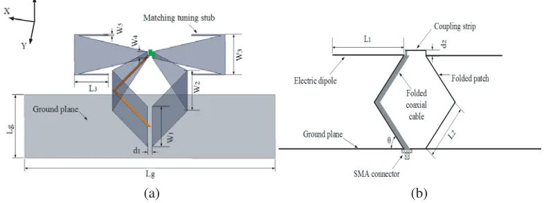
The structure of the proposed antenna with detailed dimensions is shown in Figure 1. It is formed by connecting a planar bowtie electric dipole with four matching tuning stubs to a pair of vertically folded shorted patches with a rhombic shaped cross-section. Here, the shorted patches act as a loop antenna because that the electric energy mainly distributes on the edges of the folded shorted patches. The bowtie dipole is introduced to achieve wide-bandwidth characteristic and the four tuning stubs are used to improve the antenna’s impedance matching at lower frequency bands. By attaching the four matching tuning stubs to the bowtie dipole, the total electrical length of the bowtie electric dipole is increased so that the antenna’s matching condition at lower frequencies is varied. When the dimension values of the tuning stubsL3andW5are suitably set, the antenna’s impedance matching can be effectively enhanced.
The overall length of the rhombic loop antenna should be designed as a half wavelength according to the target work band. By optimizing the antenna’s dimension values, the bowtie dipole and rhombic loop could resonate at near frequencies, and the bandwidth of the electrical-magnetic composite patch antenna can be significantly enlarged. In view of the requirements of low profile and good performance for the design, the angel θbetween the shorted patch and the ground plane is set to be 50◦.
(a) (b)
Figure 1. Geometry of the electrical-magnetic composite antenna: (a) 3D view; (b) Side view.
improved while the coupling strip’s dimension is optimal. Here, this feed structure forms a simple folded balun and makes the antenna be inherently dc grounded which satisfies the requirement for outdoor applications. The final optimal dimension values of the configurations are listed in Table 2.
Table 2. Dimension valuesfor the electrical-magnetic composite antenna (unit: mm).
Parameters L1 L2 L3 Lg W1 W2
Value 35 22 21.35 120 30 76 Parameters W3 W4 W5 d1 d2
Values 76 11.5 0.94 2.2 0.8
Figure 2 shows the simplified equivalent circuit of the proposed electrical-magnetic composite patch antenna. It is clear that the bowtie electric dipole can be equivalent to a RLC series resonant circuit and the rhombic loop antenna can be equivalent to a RLC parallel resonant circuit [12]. Without taking into account the resistance, inductance and capacitance caused by the other parts of the proposed antenna, the equivalent circuit of the proposed antenna can be simplified as presented in Figure 2. Here, RE,
LE and CE represent the resistance, inductance and capacitance generates by the electric dipole while
RM,LM andCM represent the resistance, inductance and capacitance generates by the loop antenna.
Figure 2. Simplified equivalent circuit of the electrical-magnetic composite patch antenna.
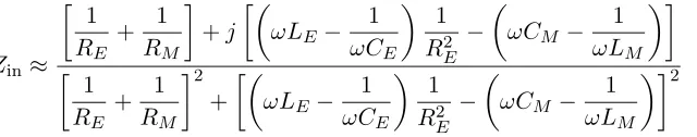
Therefore, the total input impedance of the equivalent circuitZin can be written as follow:
1
Zin
= 1
ZE +
1
ZM (1)
ZE = RE +jωLE + 1
jωCE (2)
ZM = 1
1/RM + 1/jωLM +jωCM (3)
where ZE and ZM denote the impedance of the bowtie electric dipole and the rhombic loop antenna
respectively. After calculation and simplification, we can writeZin as:
Zin≈
1
RE +
1
RM
+j
ωLE− 1
ωCE
1
RE2 −
ωCM − 1
ωLM
1
RE +
1
RM
2
+
ωLE− 1
ωCE
1
R2E −
ωCM − 1
ωLM
2 (4)
(a) (b)
Figure 3. Current distributions of the dipole-loop composite antenna at different times: (a) t = 0 (T /2); (b)t=T /4 (3T /4).
the following two equations can be satisfied simultaneously [12].
R2E = LE/CM (5)
LECE = LMCM (6)
Then, it is obviously that the imaginary part ofZincan be 0. Thus, if the electrical-magnetic composite
antenna is properly designed, the bandwidth of the electrical-magnetic composite antenna can be dramatically enlarged.
To further illustrate the operation principles of the antenna, the current distributions of the proposed antenna at different times at 5.5 GHz are analysed by ANSYS HFSS and shown in Figure 3. At time 0 and T /2 (T is the oscillation period of the electromagnetic fields) the currents are mainly distributed on the bowtie electric dipole and the currents on the surface of the rhombic loop antenna are minimized. Therefore, it can be concluded that the dipole mode is mainly excited at time 0 and
T /2. On the contrary, at time T /4 and 3T /4 the currents distributed on the bowtie electric dipole are minimized, however the currents on the rhombic loop antenna are predominant, which illustrates that the loop mode is excited at time T /4 and 3T /4.
Figure 4 is presented to show the effects of the four matching tuning stubs. The simulated |S11|
curves for various lengths of the tuning stubs with other dimensions optimal are given. It can be seen that as L3 varies, the dipole-loop composite antenna’s impedance matching at lower frequencies
obviously changes while the impedance matching at other frequencies almost stays the same. This effect indicates that while the matching tuning stubs are joined to the bowtie dipole, the antenna’s electrical length is increased and the antenna’s impedance matching at lower frequencies is improved.
3. RESULTS AND DISCUSSIONS
Based on the simulation and analysis, a prototype of the proposed antenna is fabricated and measured. The picture of the electrical-magnetic composite antenna is shown in Figure 5.
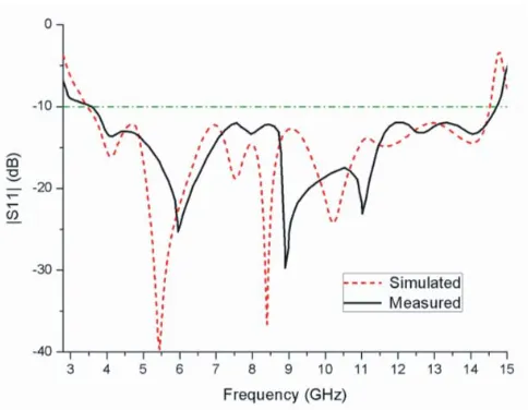
The simulated and measured|S11|curves against frequency for the loop-dipole composite antenna
are described in Figure 6. It can be observed that there is a reasonably agreement between the measured and simulated results with an acceptable discrepancy, which may be caused by the fabrication error. And an impedance bandwidth of as broad as 121.6% from 3.5 to 14.35 GHz for |S11| < −10 dB is
obtained.
Figure 4. Effects of various tuning stubs’ lengthL3.
Figure 5. Picture of the manufactured antenna.
Figure 8. Gains and radiation efficiency of the proposed antenna.
4. CONCLUSION
A very wideband dipole-loop composite patch antenna is presented in this paper. The antenna is composed of a horizontal bowtie electric dipole with four tuning stubs used for impedance matching improvement and a vertical rhombic loop antenna which is realized by a pair of folded shorted patches. The electric dipole and the loop antenna are simultaneously excited by a folded feeder which forms a simple balun and makes the antenna be dc grounded. An impedance bandwidth of 121.6% for |S11|<−10 dB from 3.5 to 14.35 GHz, good radiation patterns, low back radiation, low cross polarization
level, and a peak antenna gain of 7.7 to 9.8 dBi were obtained, which suggest that the proposed antenna could be widely used in outdoor broadband wireless communication systems.
REFERENCES
1. Lu, W. J., W. H. Zhang, K. F. Tong, and H. B. Zhu, “Planar wideband loop-dipole composite antenna,” IEEE Trans. Antennas Propag., Vol. 62, No. 4, 2275–2279, Apr. 2014.
2. Wu, X. T., W. J. Lu, J. Xu, K. F. Tong, and H. B. Zhu, “Loop-monopole composite antenna for dual-band wireless communications,” IEEE Antennas Wireless Propag. Lett., Vol. 14, 293–296, 2015.
3. Luk, K. M. and H. Wong, “A complementary wideband antenna,” US Patent, No. 11/373, Mar. 2006.
4. An, W. X., K. L. Lau, S. F. Li, and Q. Xue, “Wideband E-shaped dipole antenna with staircase-shaped feeding strip,”Electron. Lett., Vol. 46, No. 24, 1583–1584, Nov. 2010.
5. Ge, L. and K. M. Luk, “A magneto-electric dipole antenna with low-profile and simple structure,” IEEE Antennas Wireless Propag. Lett., Vol. 12, 140–142, 2013.
6. He, K., S. X. Gong, and F. Gao, “Low profile wideband unidirectional patch antenna with improved feed structure,” Electron. Lett., Vol. 51, No. 4, 317–319, Apr. 2015.
7. Zhang, Z. Y., G. Fu, S. L. Zuo, and S. X. Gong, “Wideband unidirectional patch antenna with Γ-shaped strip feed,” Electron. Lett., Vol. 46, No. 1, 24–26, Jan. 2010.
8. Ge, L. and K. M. Luk, “A wideband magneto-electric dipole antenna,” IEEE Trans. Antennas Propag., Vol. 60, No. 11, 4987–4991, Nov. 2012.
9. He, K., S. X. Gong, and F. Gao, “A wideband dual-band magneto-electric dipole antenna with improved feeding structure,”IEEE Antennas Wireless Propag., Vol. 13, 1729–1732, 2014.
11. Ge, L. and K. M. Luk, “A low-profile magneto-electric dipole antenna,” IEEE Trans. Antennas Propag., Vol. 60, No. 4, 1684–1689, Apr. 2012.