A NEW ELECTROMAGNETIC ENGINEERING PROGRAM AND TEACHING VIA VIRTUAL TOOLS
L. Sevgi
Electronics and Communications Engineering Department Do˘gu¸s University
Zeamet Sokak, No. 21, Acıbadem-Kadık¨oy, ˙Istanbul, Turkey
Abstract—The societal and technological priorities of the world
have been continuously changing because of complex computer and technology-driven developments in everywhere like communications, health, defense, economy, etc. Electromagnetic (EM) systems have become more and more complex however the explosive growth of computer capabilities has revolutionized the design and analysis of such complex systems. This has made interdisciplinary exposure necessary in modern EM engineering, also has brought up discussions of educational challenges and novel teaching approaches that confront wave-oriented EM engineering in the 21st century. This paper reviews EM computer simulation strategies and summarizes novel virtual tools that may be used in connection with classical EM lectures as well as with a newly proposed EM Engineering Program.
1. INTRODUCTION
in detail and powerful EM simulators were given in [1].
Experimentation and hands-on training are the fundamentals of EM engineering education however strong theoretical background is also a must. With the development of new computer technologies, interactive multimedia programming languages, and the internet it is now possible to simulate complex EM problems and laboratory projects of all sorts on a computer all around the world. Experiment-oriented problems can be offered without the overhead incurred when maintaining a full laboratory. At this point the question arises: should an intelligent balance be established between real and virtual experimentations and how? Another similar problem is the balance to be maintained between teaching essentials (theory) and cranking the gear (blind computer applications) [2].
Triggered by these facts, discussions and thoughts we have developed and introduced multipurpose EM virtual tools [3–18] that can be used in most of the classical EM lectures as well as in novel EM Engineering Programs (EMEP), and have been discussing them internationally [19–24]. We have always looked for something which would be useful, give physical insight, and effective so that the young EM researchers and students can use intelligently. This paper tutorially reviews these simple, easy-to-use but effective virtual tools, and, in connection, proposes a novel EMEP.
2. MODELING AND SIMULATION STRATEGIES IN EM
Computational EM is a novel area that includes research in high-performance computing, applied mathematics and physics, intelligent systems and information technologies [1]. It is a new and cost-effective way of solving complex EM problems beyond the reach of analytical methods, and the outcome is powerful software packages and virtual tools for the students, lecturers, researchers, and scientists.
Computational EM require basic understanding of fundamen-tal concepts like modeling, analytical solution, numerical solution, analytical- and numerical-based modeling, simulation, model valida-tion, code verification through canonical tests/comparisons, accredita-tion, etc. Analytical solution is the solution based on a mathematical model (usually in differential and/or integral forms) of the physical problem in terms of known, easily computable mathematical functions, such as, sine, cosine, Bessel, Hankel functions, etc. Numerical solution
is the solution based on direct discretization of the mathematical rep-resentations by using numerical differentiation, integration, etc. Semi
solu-tion based on partially derived mathematical forms that are computed numerically.
Modeling and simulation is extremely valuable in engineering if based on physics-based modeling and observable-based parameteriza-tion. It starts with the definition of the real-life problem. Its concep-tual model is the basic theory behind the real-world problem. Some dis-ciplines have already been in theirmaturestage in establishing theories. For example, Maxwell equations establish the mathematical model of
field and circuit theories in EM engineering, define the interaction of EM waves with matter, and form the basis for a real understanding of electrical problems and their solutions. All of the frequency and time domain methods use either differential or integral form of Maxwell equations. The well-known and widely used numerical methods are FEM, MoM, SSPE, FDTD and TLM (see [1] and its references).
Finite element model (FEM) analysis of a problem includes discretization of the solution region into a finite number of sub-regions or elements, derivation of the governing equations for a typical element, assembling all elements in the solution region, and solving the system of equations obtained. A major difficulty encountered in FEM analysis is data preparation, which is essentially element generation; therefore special mesh generators have been developed for this purpose. Method of Moments (MoM) is based on solving (via discretization) complex integral equations by reducing them to a system of linear equations. The equation solved by MoM generally has the form of an electric field integral equation (EFIE) or a magnetic field integral equation
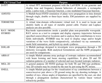
The virtual tools we have developed and their capabilities are listed in Tables 1and 2. These tools can be used as teaching aids in labs and projects of various EM lectures. Some virtual tools are general and useful for major engineering disciplines. For example, D-FFT [9] is LabView-based virtual tool where the user may train themselves via applications of Fourier transform (FT), discrete Fourier transforms (DFT) and fast Fourier transforms (FFT). It should be remembered that DFT and FFT are synthetic operations so the user should well-understood under what conditions DFT and FFT correspond to mathematical FT. If not satisfied, these conditions cause numerical effects such as aliasing, spectral leakage, scalloping loss, etc., which may all be investigated via D-FFT virtual tool.
Table 1. Basic-level virtual EM tools developed in our group.
EM Virtual Tool Purpose
D-FFT A virtual FFT instrument prepared with the LabVIEW. It can generate and display time and frequency domain behaviors of sinusoids, a rectangular pulse, a pulse train, a Gaussian function, a sine modulated Gaussian function. 1DFDTD A Matlab-based FDTD simulation of plane wave propagation in time domain
through single, double or three-layer media. EM parameters are supplied by the user.
TDRMETER A virtual time-domain reflectometer virtual tool. It is used to locate and identify faults in all types of metallic paired cable. Fourier and Laplace analyzes are also possible.
RAY / MODE HYBRID
Ray/mode representations inside a parallel plate non-penetrable waveguide. RAY serves as a tool to compute and display eigenray trajectories between specified source/observer locations and to analyze their contributions to wave fields individually. HYBRID may be used to display range and/or height variations of the wave fields comparatively, calculated via ray summation, mode field summation, and hybrid ray-mode synthesis.
DiSLAB A Matlab package designed to investigate wave propagation through a 2D dielectric waveguide. Both analytical formulations and the SSPE propagator are used for comparisons.
ARRAY A simple Matlab antenna array package of isotropic radiators accommodated with beam forming and beam steering capabilities. It plots 2D and 3D radiation patterns of a number of selected and user-located isotropic radiators. MGL-2D A general purpose 2D FDTD package for both TE and TM type problems.
Any 2D scenario may be created by the user by just using the PC mouse. SNELL A simple Matlab package for the visualization of ray contributions between a
source/receiver pair above a 2D ground using the ray shooting technique. A number of rays, whose angles of departures are specified by the user, are shot through a propagation medium characterized by various linear vertical refractivity profiles.
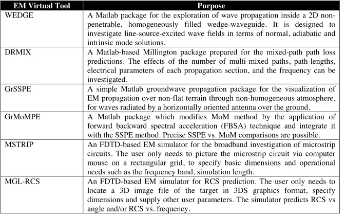
Table 2. Advanced-level virtual EM tools developed in our group.
EM Virtual Tool Purpose
WEDGE A Matlab package for the exploration of wave propagation inside a 2D non-penetrable, homogeneously filled wedge-waveguide. It is designed to investigate line-source-excited wave fields in terms of normal, adiabatic and intrinsic mode solutions.
DRMIX A Matlab-based Millington package prepared for the mixed-path path loss predictions. The effects of the number of multi-mixed paths, path-lengths, electrical parameters of each propagation section, and the frequency can be investigated.
GrSSPE A simple Matlab groundwave propagation package for the visualization of EM propagation over non-flat terrain through non-homogeneous atmosphere, for waves radiated by a horizontally oriented antenna over the ground. GrMoMPE A Matlab package which modifies MoM method by the application of
forward backward spectral acceleration (FBSA) technique and integrate it with the SSPE method. Precise SSPE vs. MoM comparisons are possible. MSTRIP An FDTD-based EM simulator for the broadband investigation of microstrip
circuits. The user only needs to picture the microstrip circuit via computer mouse on a rectangular grid, to specify basic dimensions and operational needs such as the frequency band, simulation length.
MGL-RCS An FDTD-based EM simulator for RCS prediction. The user only needs to locate a 3D image file of the target in 3DS graphics format, specify dimensions and supply other user parameters. The simulator predicts RCS vs angle and/or RCS vs. frequency.
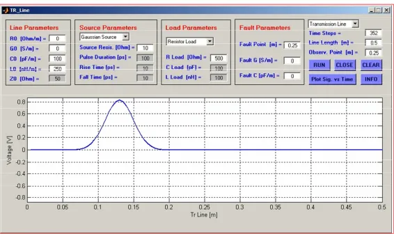
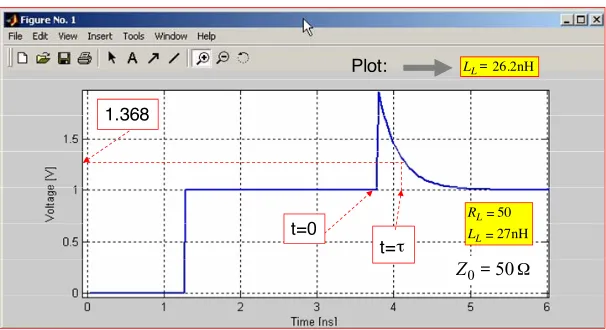
transmission line, respectively. These tools are important for the visualization of 1D pulse scattering. They can also be used to show the analogy between plane waves and transmission lines. They both are based on FDTD modeling of first order coupled differential equations of the same form. For the plane waves, the coupled equations relate spatial variations of the electric fields to the time variations of the magnetic fields (or vice versa) in terms of medium EM parameters conductivity, permittivity and permeability. The same equations relate pulsed voltage variations along the transmission line to the pulsed current variations in time via the line parameters modeled by the lumped elements RLC. These virtual tools are also very effective in showing the time and the frequency domain characteristics of plane waves and transmission lines using DFT or FFT. The Laplace transform is also used in the TDRMeter to show the transient effects along the line [12]. Figs. 1 to 4 show some examples obtained using the TDRMeter tool.
Figure 1. The front panel of the TDRMeter package, resistive termination, a Gaussian pulse traveling towards the load (a 50 Ω transmission line,Rs= 1 0 Ω,RL= 100 Ω).
1
4
2 3
5 6
Figure 2. Gaussian pulse injection along a transmission line
short-circuited at both ends. Graphs show different time instants (1: pulse injection, 2: detachment of the right- and left-traveling pulses, 3, 4: pulses propagating towards left and right, 5, 6: right-propagating pulses, one from the source, the other reflected from the left boundary with the opposite phase).
nH L
pF C R
L L L
10 5 50
50
0
Z
incident reflected
(a)
(b)
Ω
Ω
= = =
=
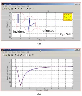
Figure 3. (a) Signal vs. time at mid point of a 50 Ω, 0.5 m TL
under parallel RLC termination (RL = 50 Ω, CL = 5 pF, LL =
10 nH). Matched termination is used at the source (Rs = 50 Ω).
Pulse length = 400 ps, (b) Voltage reflection coefficient vs. frequency obtained with the FFT procedure; Solid: TD simulation result, Dashed: Analytical exact solution.
nH L R
L L
27 50
50 0
Z
nH LL 26.2 Plot:
t=0
t= 1.368
τ
=
=
=
= Ω
Figure 4. Signal vs. time (step response) at mid point of a 50 Ω,
0.5 m TL under serial RL termination (RL = 50 Ω, LL = 27 nH).
Matched termination is used at the source (Rs = 50 Ω). The value
of the inductor calculated from the plot is 26.2 nH.
Also, reflections due to various types of transmission structures, impedance effects of vias, signal and power line couplings, etc., on printed circuits with smaller and smaller dimensions make signal integrity one of the most important and complex EMC problems. Therefore, the virtual tool may be particularly helpful for a student or circuit designer in the evaluation of signal integrity.
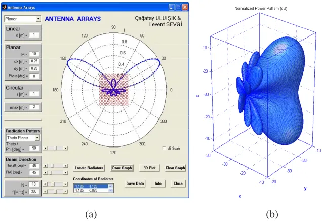
ANTEN [14] is a Matlab package to visualize beam forming and beam steering capabilities of various linear, circular, and planar arrays of isotropic radiators. The user may form any kind of an array and observe radiation patterns in 2D or 3D (for vertical or horizontal polarizations). An interesting feature is added in designing planar arrays. The user may design an arbitrary array by just locating arbitrary number of isotropic radiators using the PC mouse. Inter-element phasing is done automatically to steer the beam of the designed array to the specified beam pointing direction. An example produced via ANTEN is given in Fig. 5.
(a) (b)
Figure 5. A 1 0×10 planar array, (a) horizontal plane 2D pattern,
(b) 3D radiation pattern (f = 300 MHz, inter-element distances are 0.25 m in bothx- andy-directions, the beam angles are θ0 = 45◦ and ϕ0= 45◦.
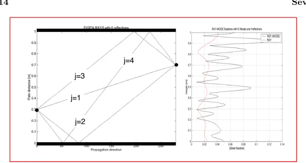
HYBRID virtual tools are very useful. Two examples are presented in Figs. 6 and 7. As shown, the user may visualize individual or collective contributions of the rays and/or the modes. The same is true for the WEDGE and DiSLAB virtual tools. The 2D parallel plate waveguide with penetrable and non-penetrable boundaries are canonical structures in teaching rays representation, eigenvalue (source-free) and Green’s function (source-driven) problems [15, 16].
j=1
j=2 j=3
j=4
Figure 6. (Left) first four eigenarray inside a 1m-wide parallel
plate waveguide for a set of parameter (distance = 5.6 m, source height = 0.3 m, observer height = 0.7 m, f = 2387 MHz, ka = 50,
n = 1). The number of propagating modes for these parameters is 15. (Right) Wave field vs. height calculated via both mode and ray summations (mode summation is the reference solution).
Figure 7. Same with the Fig. 6 but forn= 1to 5. As observed, ray
solution approaches to the reference (mode) solution as the rays stuff the waveguide.
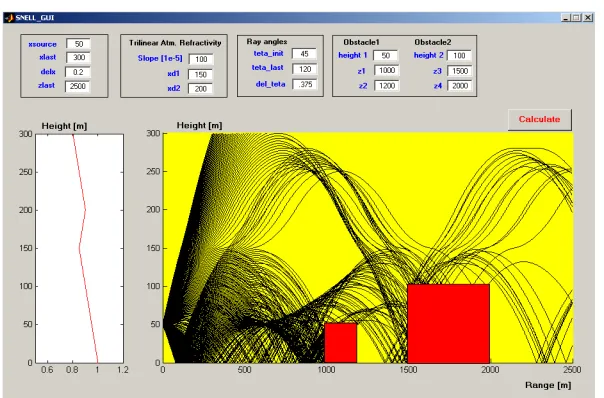
Figure 8. The front panel of the Matlab package SNELL and ray shooting through an environment with a vertical tri-linear refractivity profile having two obstacles along the propagation path (source height = 50 m, maximum height = 300 m, layer height = 0.2 m, maximum range = 2500 m, first ray angle = 45◦, last ray angle = 120◦, ray increment = 0.375◦, Refractivity slope = 0.001, the heights of ducting and anti-ducting are 80 m and 150 m, respectively, 1. obstacle: height = 50 m, base length = 200 m, range = 1000 m; 2. obstacle: height = 100 m, base length = 500 m, range = 1500 m).
terrain profiles and run the simulations over these profiles and obtain path loss vs. range curves. This is really important, since it gives a possibility of comparing a real-life measurement data against simulation data obtained via the SSPE and/or MoM propagators. Finally, MGL-2D is an FDTD based 2D propagator which can be used for broad range of EM problem simulations. Some examples are presented in Figs. 9–11.
Figure 9. The SSPE virtual tool and propagation through tri-linear atmosphere over an irregular terrain; frequency 100 MHz, maximum range 50 km, maximum height 1500 m, transmitter height 250 m, antenna tilt 2 degrees upwards, and beamwidth 1degrees. Linearly increasing and decreasing refractivity segments have slopes of 5000 M/km.
Figure 10. The MGL-2D virtual tool and outdoor propagation
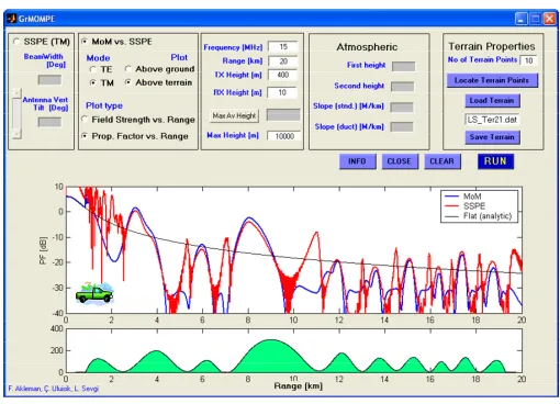
Figure 11. A typical non-flat terrain scenario (a surface with many smooth irregularities; with range in [km] and height in [m]) and propagation factor in dB vs. range in [km] for the TM-type problem (f = 15 MHz, maximum range = 20 km, transmitter height = 400 m, receiver height = 10 m).
Figure 12. The MSTRIP virtual tool; a typical 4-port coupler, a
Figure 13. The front panel of the MGL-RCS package and the 3D discrete model of an air target (a 50 m-long DC-10 jet) imported from a 3DS file.
f=80MHz
18 dB
=4 f=40MHz
30 dB
=2λ λ
(a) (b)
Figure 14. FDTD vs. NEC for angular bi-static RCS predictions
at two different cases; (a) f = 40 MHz, θi = 90◦, ϕi = 0◦, ϕs = 0◦,
0◦ ≤θs≤360◦ with angular resolution of ∆θ= 3◦, Vertical scan,σϕϕ
-case. (b) f = 80 MHz, θi = 90◦, ϕi = 90◦,ϕs = 90◦, 0◦ ≤θs ≤ 360◦
with angular resolution of ∆θ = 3◦, Vertical scan, σϕϕ-case. Solid
(red): FDTD, Dashed (blue): NEC2. Maximum plot values are given on top right.
4. A NOVEL EM ENGINEERING PROGRAM — EMEP
Most of ECE engineering program have EM lectures such asEM Fields,
EM Waves, Antennas and Propagation, Introduction to Microstrip Circuits, Wireless Communication, EMC Engineering, Filter Theory,
Radar and Sensing Systems, etc. However, current complexity of most of the EM problems necessitates revisit of the number and contents of these lectures. A novel EMEP program, partially based on the presented virtual tools can be designed with a reduced number of lectures and credits. Essential topics can be covered in four different lectures;EM Engineering I, II, and III,Microwave Engineering. Other related engineering topics may be covered in the lecture EM Special Topics. Fundamentals topics to be covered inside the first four lectures are listed in Tables 3 and 4.
Junior-level EM courses basically covers EM topics in one-and two-dimension. After summarizing current challenging EM problems, and reviewing Fourier and discrete Fourier fundamentals, the first quarter (nearly three weeks) of the first lecture EM Eng-I
Table 3. Junior-level EM lectures and topics to be covered in the proposed EMEP.
EM Engineering - I
EM Engineering & Challenging Problems Fourier transforms, DFT & FFT LabView-based FFT VT
Maxwell Equations
Time & Frequency Representations Electrostatics and Magnetostatics Electrodynamics
Scattering, Radiation & Diffraction
Spherical waves, Cylindrical waves Poynting theorem & EM Power Wave/matter interaction
Plane Waves & 1D FDTD Solutions Matlab-based 1D FDTDVT
Plane waves Tran smission Line Analogy Transmission Line Theory
Matlab-based TDRMeter VT
EM Engineering - II
Complex 2D EM Problems
2D Parallel Plate Waveguide & Ray/Mode Solutions (HYBRID VT)
1D Sturm-Liouville Prolem (STURM VT) Ray tracing, Ray Shooting & SNELL VT
Friis Formulae & Path Loss Definiton Propagation Through Atmosphere, Refractivity Effects & SSPE VT
Dielectric Slab Waveguide & DiSLAB
FDTD-based MGL-2D VT
EM (Hertz & ring) Dipoles Antenna Fundamentals
EMC & Communication Antennas Arrays, Beam Forming& Steering Matlab-based ARRAY VT
Wire Antennas & NEC Modeling 3D Rectangular waveguides Resonators
.
.
.
.
.
.
.
.
.
.
.
.
.
.
.
.
.
.
.
.
.
.
.
.
.
.
_.
.
.
.
.
.
.
.
Table 4. Senior-level EM lectures and topics to be covered in the
proposed EMEP.
EM Enginering - III
Fundamentals of EMC, EMI & BEM Signals and Noise in Electromagnetics Non-Linearity Effects & Harmonics EMC Standards, Tests & Measurements EMC & Shielding Effectiveness (SE VT) Specific Absorption Rate (SAR VT)
N-port devices & S-parameters LC TL Equivalence
Microstrip Lines & Microstrip Circuits Broadband Filter Design
Chebychev and Butterworth Filters FDTD-based 3D MSTRIP VT
EM Engineering - IV (Special Topics) Computational Electromagnetics Finite Difference Time Domain Method Finite Element Method
Method of Moments Radars and Sensing Systems
Detection & Tracking Algorithms RCS Modeling & Simulation
MGL-RCS VT
Multi-Sensor Surveillance systems Opical Fibers, Wireless Communication
second quarter; which focuses on the plane waves. The transmission line theory is summarized in the third quarter starting with the discussion of plane wave — transmission line analogy. The last quarter is reserved for the virtual lab experimentations using the two virtual tools, 1DFDTD and TDRMeter [12]. Resonance effects of the plane wave propagation in a 1D finite region and/or along a finite length short/open circuited transmission line can be presented using the discrete Fourier transformation tools DFT or FFT. Also, transients along a transmission line can be presented using the Laplace transformation and the TDRMeter data. Numerical experimentations of the excitation and/or observation of the resonances (i.e., modes) in 1D can be performed easily.
Fundamental EM problems in 2D are included in the second lecture, EM Eng–II. Classical 2D parallel plate waveguide with penetrable as well as non-penetrable boundaries are discussed in this course. Ray, mode and hybrid solutions are presented together with the visual capabilities of the RAY, HYBRID [15] and DiSLAB virtual tools. Ray-mode representations and ray shooting methods are covered in this lecture. The relation between eigenvalue and Green’s function problems are related via the Sturm-Liouville problem. The FDTD-based virtual tool MGL-2D [11] can be used to create many realistic EM scenarios, from indoor-outdoor propagation to tunneling, waveguides to resonators, etc. Antennas and radiation topics are also covered in this lecture.
A new EM Engineering Program is introduced to cope with current challenges in engineering education. The program is based on two junior and two-senior level EM Engineering courses. Various powerful virtual tools which play essential roles in teaching in this new EMEP are also discussed. It should be noted that, an intelligence balance between EM theory and numerical simulations must be established when using this EMEP.
REFERENCES
1. Sevgi, L., Complex Electromagnetic Problems and Numerical Simulation Approaches, IEEE Press & John Wiley and Sons Inc., NJ, June 2003.
2. Sevgi, L. and I. C. G¨oknar, “An intelligent balance in engineering education,” IEEE Potentials Magazine, Vol. 23, No. 4, 40–41, Oct./Nov. 2004.
3. Uluı¸sık, C¸ ., G. C¸ akır, M. C¸ akır, and L. Sevgi, “Radar Cross Section (RCS) modeling and simulation: Part I — Definitions, strategies, and canonical examples,”IEEE Antennas and Propagation Magazine, Vol. 50, No. 1, Feb. 2008.
4. C¸ akır, G., M. C¸ akır, and L. Sevgi, “Radar Cross Section (RCS) modeling and simulation: Part II — A novel FDTD-based RCS prediction virtual tool,” IEEE Antennas and Propagation Magazine, Vol. 50, No. 2, Apr. 2008.
5. Akleman, F. and L. Sevgi, “A novel MoM- and SSPE-based groundwave propagation field strength prediction simulator,”
IEEE Antennas and Propagation Magazine, Vol. 49, No. 5, 69– 82, Oct. 2007.
6. Sevgi, L., “A mixed-path groundwave field strength prediction virtual tool for digital radio broadcast systems in medium and short wave bands,” IEEE Antennas and Propagation Magazine, Vol. 48, No. 4, 19–27, Aug. 2006.
7. G¨und¨uz, S., G. C¸ akır, and L. Sevgi, “A generic microstrip structure for the realization of all-type broadband filters,”
Microwave and Optical Technology Letters, Vol. 48, No. 12, 2390– 2393, Dec. 2006.
8. Sevgi, L., “Virtual tools/labs in electrical engineering education,”
Computer Engineering Education in the 21st Century: Issues, Perspectives and Challenges, 2006.
9. Sevgi, L. and C¸ . Uluı¸sık, “A labview-based virtual instrument for engineering education: A numerical fourier transform tool,”
ELEKTRIK, Turkish J. of Electrical Engineering and Computer Sciences, Vol. 14, No. 1, 129–152, Special issue on Electrical and Computer Engineering Education in the 21st Century: Issues, Perspectives and Challenges, 2006.
10. C¸ akır, G., M. C¸ akır, and L. Sevgi, “A novel virtual FDTD-based microstrip circuit design and analysis tool,” IEEE Antennas and Propagation Magazine, Vol. 48, No. 6, 161–173, Dec. 2006. 11. C¸ akır, G., M. C¸ akır, and L. Sevgi, “A multipurpose FDTD-based
two dimensional electromagnetic virtual tool,” IEEE Antennas and Propagation Magazine, Vol. 48, No. 4, 142–151, Aug. 2006. 12. Sevgi, L. and C¸ . Uluı¸sık, “A matlab-based transmission line
virtual tool: Finite-difference time-domain reflectometer,” IEEE Antennas and Propagation Magazine, Vol. 48, No. 1, 141–145, Feb. 2006.
13. Sevgi, L., C¸ . Uluı¸sık, and F. Akleman, “A matlab-based two-dimensional parabolic equation radiowave propagation package,”
IEEE Antennas and Propagation Magazine, Vol. 47, No. 4, 184– 195, Aug. 2005.
14. Sevgi, L. and C¸ . Uluı¸sık, “A matlab-based visualization package for planar arrays of isotropic radiators,” IEEE Antennas and Propagation Magazine, Vol. 47, No. 1, 156–163, Feb. 2005. 15. Felsen, L. B., F. Akleman, and L. Sevgi, “Wave propagation inside
a two-dimensional perfectly conducting parallel plate waveguide: Hybrid ray-mode techniques and their visualisations,” IEEE Antennas and Propagation Magazine, Vol. 46, No. 6, 69–89, Dec. 2004.
16. Sevgi, L., F. Akleman, and L. B. Felsen, “Visualizations of wave dynamics in a wedge-waveguide with non-penetrable boundaries: Normal, adiabatic, and intrinsic mode representations,” IEEE Antennas and Propagation Magazine, Vol. 49, No. 3, 76–94, Jun. 2007.
17. Sevgi, L., “A ray shooting visualization matlab package for 2D ground wave propagation simulations,” IEEE Antennas and Propagation Magazine, Vol. 46, No. 4, 140–145, Aug. 2004. 18. Sevgi, L., “Modeling and simulation strategies for electromagnetic
Tribute to Leopold Benno Felsen, Jun. 2007.
19. Uluı¸sık, C¸ . and L. Sevgi, “Numerical modeling and simulation studies of 2D radiowave propagation over non-flat terrain and through inhomogeneous atmosphere,” Springer Proceedings in Physics Series, Vol. 104, 45–54, Complex Computing Networks, Jan. 2006.
20. Sevgi, L., “From engineering electromagnetics towards electro-magnetic engineering,” ELECO 2007, 5th International Confer-ence on Electrical and Electronics Engineering, Bursa, Turkey, Dec. 5–9, 2007.
21. Sevgi, L., “Electromagnetic engineering and teaching via virtual computer tools,” EUROCON 2007 the International Conference on Computer as a Tool, a half-day short course, Warsaw, Poland, Sept. 9–12, 2007.
22. Sevgi, L., “Modeling and simulation strategies in antennas and propagation: Novel virtual tools,” EuCAP 2006, the First ESA European Conference on Antennas and Propagation, a half-day short course, Nice-France, Nov. 6–10, 2006.
23. Sevgi, L., “Modeling and simulation strategies in electromagnet-ics: Teaching via virtual tools,”IEEE AP-S International Sympo-sium&USNC/URSI National Radio Science AMEREM Meeting, a half-day short course, Albuquerque, New Mexico, USA, Jul. 9– 14, 2006.