ISSN(Online): 2319-8753 ISSN (Print) : 2347-6710
I
nternational
J
ournal of
I
nnovative
R
esearch in
S
cience,
E
ngineering and
T
echnology
(A High Impact Factor, Monthly, Peer Reviewed Journal)
Visit: www.ijirset.com
Vol. 6, Issue 10, October 2017
Non- Linear Inverted Pendulum System by
Multirate Output Feedback
Swami B.S.1, Nagrale R.M.2
P.G. Student, Department of Control System Engineering, MBES Engineering College, Maharashtra, India1 Associate Professor, Department of Control System Engineering, MBES Engineering College, Maharashtra, India2
ABSTRACT: In this paper Multirate output feedback (MROF) based control method for non linear systems is designed. In this method two controllers, (1) linear quadratic regulator and (2) fast output sampling, in which the system output is sampled at the faster rate as compared to control input. In the first approach of fast output sampling, the states of the system can be computed from the output of the system. While in second approach, previous control input along with past system outputs are used to calculate the present control input. These controllers are the part of MROF in which states of system can computed from output of the system.
KEYWORDS: Fast output sampling technique, Sampling feedback, Simulink.
I. INTRODUCTION
The aforementioned control strategies are based on full–state feedback. Using the concept multirate output feedback where in the system output is sampled at a faster rate compared to the control input. Consider the system sampled with a sampling time of ∆=T∕N sec. Where N is an integer greater than the observability index of the system. Inverted pendulum is a difficult system to control, it is inherently unstable and non linear system. To control the pendulum it need to treated as linear, without error. Here, inverted pendulum can be control using three controllers, first one is LINEAR Quadratic Regulator, Second Is Fast Output Sampling with modified and new modified, those controllers have simulation result which will be compared to know the effect of different control technique Inverted pendulum is controlled by using the basic concept of space satellite, rockets, landing of aircrafts, balancing of ship against tide, seismometer. The system is non-linear, but for, if the operating region is small then, system is approximates to linear.
ISSN(Online): 2319-8753 ISSN (Print) : 2347-6710
I
nternational
J
ournal of
I
nnovative
R
esearch in
S
cience,
E
ngineering and
T
echnology
(A High Impact Factor, Monthly, Peer Reviewed Journal)
Visit: www.ijirset.com
Vol. 6, Issue 10, October 2017
II. REALATED WORK
1. Linear Quadratic control
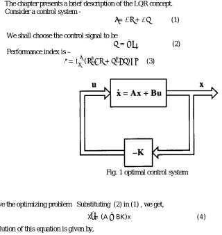
The chapter presents a brief description of the LQR concept. Consider a control system -
ẋ= + (1)
We shall choose the control signal to be
=− (2) Performance index is –
=∫ ( + ) (3)
Fig. 1 optimal control system
To solve the optimizing problem Substituting (2) in (1) , we get,
Ẋ = (A−BK)x (4)
The solution of this equation is given by,
= ( ) (0) (5)
If matrix K is chosen properly, the matrix A – BK can be made asymptotically stable matrix, and for all x(0)≠0 it is
possible to make x(t) approach zero as t approaches infinity.
Performance index J can be evaluated as
= ∫∞ ( + ) = − |∞ (6)
= - ∞+ 0 (7)
ISSN(Online): 2319-8753 ISSN (Print) : 2347-6710
I
nternational
J
ournal of
I
nnovative
R
esearch in
S
cience,
E
ngineering and
T
echnology
(A High Impact Factor, Monthly, Peer Reviewed Journal)
Visit: www.ijirset.com
Vol. 6, Issue 10, October 2017
State feedback gain is designed using matrix,
Q=
0.1
0
0
0
0
0.1
0
0
0
0
0.1
0
0
0
0
0.1
, R = 1
2. Fast Output Sampling
:-Fast output sampling is a kind of MROF in which the system output is sampled at a faster rate as compared to the control input.
̇( ) = ( ) + ( ) (10) ( ) = ( ) (11)
Fig. Visualization of fast output sampling feedback
As illustrate in Figure. When the system is sampled at the rate of the equivalent discrete-time system is,
( + 1) = ( ) + ( ) (11)
y(k) = (k) (12)
( + 1) = ∆ ( ) + ∆ ( ) (13)
Where, ∆= In FOS, output measurements are taken at time instants t = l∆, where l=0,1,2,…,N-1. The control signal which is applied during the interval ≤ ≤( + 1) , Where l = 0,1,2,3,…N-1; by using these values in above equation we get some values which is illustrate in matrix form as follow –
yk=
0 2 . . . (N 1)
y
y
y
y
; C0 = ..
. 1 2 N
C
C
C
C
; D0 =
ISSN(Online): 2319-8753 ISSN (Print) : 2347-6710
I
nternational
J
ournal of
I
nnovative
R
esearch in
S
cience,
E
ngineering and
T
echnology
(A High Impact Factor, Monthly, Peer Reviewed Journal)
Visit: www.ijirset.com
Vol. 6, Issue 10, October 2017
From the above matrix the output equation is
= + (14) Output feedback signal is given as,
( ) = (15)
( )= (16)
Sampling equation will be given as
= ( + )(+ ) (17)
( ) = ̅ ( ) (18)
By comparing above equation
= ̅ (19)
3. Modified approach of fast output sampling
Modified approach of fast output sampling technique
( )= + (20)
( ) = ( )+ ( )
Where,
= − ( )
= ( ) )
State variable is calculated by using y(k) and ( )
Consider the equation as-
( ) = ( ) ) + [ − ( ) ] ( )(21)
4. New modified approach for fast output sampling technique By adding the past output ( )∆ to
= 0 2 . . . (N 1)
y
y
y
y
= ( 1) ( 1)( 1) 2
. . . ( ) k k k k
y
y
y
y
= ( 1) ( 1) ( 1) . . . ( ) k k k ky
y
y
y
= 0 . . .(N )
y
y
y
y
, ( ) = C
( ) ( ) ( ) . . . ( ( 1) )
k k k k N
x
x
x
x
But we have a equation,
( ) = ∆ ( ∆)+ ∆ ( )
ISSN(Online): 2319-8753 ISSN (Print) : 2347-6710
I
nternational
J
ournal of
I
nnovative
R
esearch in
S
cience,
E
ngineering and
T
echnology
(A High Impact Factor, Monthly, Peer Reviewed Journal)
Visit: www.ijirset.com
Vol. 6, Issue 10, October 2017
From above equations,
( ) = C
1 1
( ) ( 1)
( )
( ) ( )
2
( ) ( )
. . . 2 1
( ) 0 ( )
k k
k
k k
k k
N
N j
k j k
x
u
x
x
u
x
u
x
u
From above matrix,
( ) =
0 0( 2 ) 0 0
( 1)
1 1
0 0 0
[( ) ] ( 0 ( ) T ) k T
k T
T T T
k
F P P P y F P P P S u
u
From the above equations we can usethese on simulation to obtain best performance. Thus the gain of MROF is K = [0.3162 1.4440 56.5962 -10.4046]. After 0.07 second, the cart is forced 40N/m force to move the cart from the 0.1 of its initial condition. At the same time, the pendulum rod must remain in straight position. By the use of FOS on new modification , it is observed that the cart position have settle time 10.72 second and pendulum angle stable in 1.6 second as compared to the other controller. The settling time is reduced by 75%.
III. INVERTED PENDULUM SYSTEM
ISSN(Online): 2319-8753 ISSN (Print) : 2347-6710
I
nternational
J
ournal of
I
nnovative
R
esearch in
S
cience,
E
ngineering and
T
echnology
(A High Impact Factor, Monthly, Peer Reviewed Journal)
Visit: www.ijirset.com
Vol. 6, Issue 10, October 2017
Fig. Inverted parametric presentation
Dynamics of inverted pendulum –
= + sin
= cos
Horizontal motion of centre of gravity of inverted pendulum rod is given by,
= ( + sin )=
Similarly, vertical motion of centre of gravity of inverted pendulum rod is given by,
= ( cos )= −
ẋ( ) = ( ) + ( ), ( ) = ( )
Where, A is a system matrix, B is a input matrix, and C is a output matrix.
To obtain the value of A,B,C we have to consider equation,
( + ) ̈+ ̇+ ̈=
( + ) ̈+ ̈=
Table-1 gives the information about symbols and prescription used in the work.
ISSN(Online): 2319-8753 ISSN (Print) : 2347-6710
I
nternational
J
ournal of
I
nnovative
R
esearch in
S
cience,
E
ngineering and
T
echnology
(A High Impact Factor, Monthly, Peer Reviewed Journal)
Visit: www.ijirset.com
Vol. 6, Issue 10, October 2017
IV. EXPERIMENTAL RESULTS
Figures shows the results of simulink , waveforms are seprated with the different controllers used.
(1) Result (a),(b),(c) are generated using LQR controller, basically in this given input force shown by (a),effect of cart position is shown by (b), and also fig.(c) shows the effect on pendulum angle represented by blue colored line.
(a) (b)
(c)
(2) Figure (d),(e),(f) shows the result about inout force,pendulum angle,cart position respectively, which are obtained by using modified Fast Output Sampling controller, represented by red dotted lines.
(d) (e)
(f)
ISSN(Online): 2319-8753 ISSN (Print) : 2347-6710
I
nternational
J
ournal of
I
nnovative
R
esearch in
S
cience,
E
ngineering and
T
echnology
(A High Impact Factor, Monthly, Peer Reviewed Journal)
Visit: www.ijirset.com
Vol. 6, Issue 10, October 2017
(g) (h)
(i)
V. CONCLUSION
An inverted pendulum is stabled in less time by sampling the control input in delay. Output is compared with the state feedback controller and modified FOS technique to show the efficient method. We can find an optimal solution by multirate output feedback method.
REFERENCES
[1] G. Reddy, B. Bandyopadhyay, and A. P. Tiwari, “Discrete-Time Sliding Mode Control for Two-Time-Scale Systems,” Proc. of IEEE Intr. Conf. on Industrial Electronics, pp. 170–175, November 2008.
[2] G. Bartolini, A. Ferrara, and A. Utkin, “Adaptive Sliding Mode Control in Discrete-Time Systems,” Automatic, vol. 31, no. 5, pp. 769–773, 1995. [3] C. Edwards and S. K. Spurgeon, Sliding Mode Control: Theory and Applications. Bristol, PA: Taylor and Francies, 1998.
[4] J. Y. Hung, W. Gao, and J. C. Hung, “Variable Structure Control: A Survey,” IEEE Transactions on Industrial Electronics, vol. 40, pp. 2–22, February 1993.
[5] L. B. Prasad, B. Tyagi, and H. O. Gupta, “Otimal Control of Nonlinear Inverted Pendulum Dynamical System with Disturbance Input using PID Controller and LQR,” Proc.
of IEEE Intr. Conf. on Control System, Computing and Engineering, pp. 540–544, November 2011.
[6] C. T. Chen, Linear System Theory and Design. New York: Oxford University Press, 1999 ISBN 0-19511777-8
[7] Yahaya MD.Sam received the MS degree in control engineering from university of Sheffield in 1988. His research interest in multirate output feedback controller for inverted pendulum.pp. 217-223
[8] H. Werner and K. Furuta, “Simultaneous Stabilization based on Output Measurement,” Kybernetica, vol. 31, no. 4, pp. 395–414, 1995.
[9] A. P. Tiwari, G. D. Reddy, and B. Bandyopadhayay, “Design of Periodic Output Feedback and Fast Output Sampling based Controllers for Systems with Slow and Fast Modes,” Asian Journal of Control, vol. 14, pp. 271–277, January 2012.
[10] V. L. Syrmos, C. T. Abdallah, P. Dorato, and K. Grigoriadis, “Static Output Feedback-A Survey,” Automatica, vol. 33, pp. 125–137-1997.