ISSN(Online): 2319-8753 ISSN (Print): 2347-6710
I
nternational
J
ournal of
I
nnovative
R
esearch in
S
cience,
E
ngineering and
T
echnology
(A High Impact Factor & UGC Approved Journal)
Website: www.ijirset.com
Vol. 6, Issue 9, September 2017
Micro-programmed Parallel FIR Filter using
Globally Asynchronous Locally Synchronous
(GALS) System
Suma Gurulingaiah Charantimath, Ravi S M
Assistant Professor, Department of Electronics and Communication, PDIT College, Hospet, Karnataka, India
Assistant Professor, Department of Mechanical, SIT College, Mangalore, Karnataka, India
ABSTRACT: In this paper, we propose the design of globally asynchronous locally synchronous (GALS) micro-programmed parallel finite impulse response (FIR) filter using pipelined GALS Baugh Wooley Multiplier. The primary objective is to demonstrate low power implementation of micro-programmed parallel GALS FIR filter for digital signal processing applications. Full synchronous micro-programmed parallel FIR filter and GALS micro-programmed FIR filter are implemented using same FPGA and almost amelogic cells for fair benchmarking. The four tap synchronous and GALS micro-programmed parallel FIR filter is coded in VHDL and implemented in vertex 5 FPGA device. GALS micro-programmed parallel FIR filter is more power efficient as compared to synchronous filter.
KEYWORDS: Low power, GALS, Micro-programmed, Parallel, FIR Filter.
I. INTRODUCTION
Low power operation is desirable in all the digital signal processing systems. Most of the digital signal processing systems is fully synchronous but a trend, as detailed in the International Technology Roadmap for Semiconductors (ITRS) [1], for an increasing use of asynchronous logic from the present 15 % to 49 % in 2024.In some of these SoC’s, asynchronous signaling scheme [2], [3] were used for synchronization between the different fully synchronous
modules that is opposed to fully asynchronous systems where asynchronous signaling scheme are used for both between modules (inter-modules) and within modules (intra-module). This hybrid inter-module asynchronous cum intra-module synchronous, termed Globally-Asynchronous-Locally-Synchronous (GALS) may be advantageously exploited to simplify some challenging design issues [4]. For the asynchronous-to-synchronous data transfer [2], [5] or vice-versa, the GALS approaches may be generally categorized by its clocking schemes, pausible clocking and the data-driven clocking. FIR filter is the fundamental digital signal processing (DSP) operation for many DSP systems. It finds applications in audio, image and video processing, wireless communication, noise removal etc. In most of the applications digital filters are used to implement frequency-selective operations. Therefore, specifications are required in the frequency-domain in terms of the desired magnitude and phase response of the filter. FIR with constant coefficients is a linear time invariant digital filter. The output of an FIR of order or length (N), to an input time-series x[n], is given by a finite version of the convolution sum given in (1) and (2),
ISSN(Online): 2319-8753 ISSN (Print): 2347-6710
I
nternational
J
ournal of
I
nnovative
R
esearch in
S
cience,
E
ngineering and
T
echnology
(A High Impact Factor & UGC Approved Journal)
Website: www.ijirset.com
Vol. 6, Issue 9, September 2017
where h[n] is called as filter coefficients or impulse response and y[n] is the output signal. For linear time invariant system, it can be expressed in Z domain as given in (3)
( ) = ( )ℎ( ) (3) Where h(z) is the FIR filter transfer function defined in Z domain by (4)
ℎ( ) = ∑ h[k] z (4)
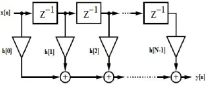
Direct form implementation of linear time invariant FIR filter using delay element, adder and multiplier is shown in fig 1.
Fig. 1 Direct form FIR filter The difference equation for 4-tap FIR filter (N = 4) is given in (5)
[ ] = ∑ x[k]h[n−k]
[ ] = [0] ℎ[ ] + [1] ℎ[ −1] + [2] ℎ[ −2] + [ 3] ℎ[ −3] (5)
Direct form FIR filters are also known as tapped delay line or transversal filters. The size of the FIR filter is determined by the number of coefficients h[n]. N-tap FIR filter consist of N delay elements, N multipliers and N-1 adders or accumulators. Generally a linear phase response in the pass band is desirable for many applications especially in communication. It is shown in [6] that linear phase is achieved if the impulse response is symmetric or anti-symmetric and hence it is preferable to use anti-causal framework [7] given in (6) obtained from (4)
ℎ ( ) = ∑( ()/ )/ h[k]z (6)
ISSN(Online): 2319-8753 ISSN (Print): 2347-6710
I
nternational
J
ournal of
I
nnovative
R
esearch in
S
cience,
E
ngineering and
T
echnology
(A High Impact Factor & UGC Approved Journal)
Website: www.ijirset.com
Vol. 6, Issue 9, September 2017
[9]. In this paper, we proposed FPGA implementation of GALS micro-programmed parallel 4-tap FIR filter and its comparison with fully synchronous parallel micro-programmed 4-tap FIR filter using GALS & synchronous Baugh Wooley multiplier respectively given in [10]. The primary objective of the design is to demonstrate low power implementation of GALS FIR Filter. The paper is organized as follows section I introduces GALS and FIR Filter, section II describes Baugh Wooley multiplier and section III describes microprogrammed FIR filter architecture. Section IV provides in detail design of synchronous and GALSmicroprogrammed parallel FIR filter. Results are discussed in section V and finally concluded in section VI.
II. BAUGH WOOLEY MULTIPLIER
The Baugh Wooley multiplication algorithm [11] is developed to designed regular 2’s complement multipliers. It effectively handles sign bit during the computation of partial products. Let a and b be the two n-bit signed numbers can be represented as,
A= −a 2 +∑ a 2 (7)
B= −b 2 +∑ b 2 (8)
The result of multiplication of a and b is represented as P=AxB P = (−a 2 +∑ a 2) x (−b 2 + ∑ b 2)
P = a b 2 +∑ a 2 ∑ b 2 −a 2 ∑ b 2 −b 2 ∑ a 2 (9)
The last two terms in equation (9) are n-1 bits each that are extended from position 2n-1 to 22n-3. We pad zeros to remaining bits to obtain 2n bit number in order to extent binary weight from 20 to 22n-1. Rather than subtracting the last two terms, we can obtain 2’s complement of the last two terms and add all terms to obtain final product. Let z be one of the last two terms, it can be represented in equation (10) with zero padding.
= −0 22n-1+0 22n-2+ 2n-1∑ 2 z+0 ∑ 2 (10)
ISSN(Online): 2319-8753 ISSN (Print): 2347-6710
I
nternational
J
ournal of
I
nnovative
R
esearch in
S
cience,
E
ngineering and
T
echnology
(A High Impact Factor & UGC Approved Journal)
Website: www.ijirset.com
Vol. 6, Issue 9, September 2017
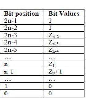
Table 2 Bit patterns
After obtaining 2’s complement of z, the new bit value for –z is shown in table I.Let z1 and z2 be last two terms in
equation (3) then addition of –z1 + (-z2) results in following bit patterns at most significant bits and bit position n shown
in table II. Hence the product p in equation (9) can be given as
Let us assume if a and b are 8-bit numbers then product p is given as
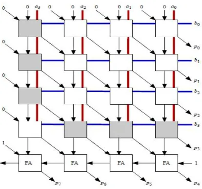
Fig. 2 shows the implementation structure of 4-bit Baugh Wooley multiplier and fig. 3 shows the corresponding internal structure of cells.
ISSN(Online): 2319-8753 ISSN (Print): 2347-6710
I
nternational
J
ournal of
I
nnovative
R
esearch in
S
cience,
E
ngineering and
T
echnology
(A High Impact Factor & UGC Approved Journal)
Website: www.ijirset.com
Vol. 6, Issue 9, September 2017
Fig. 3 Internal structure of cells
III. MICRO-PROGRAMMED FIR FILTER ARCHITECTURE
The micro-programmed FIR filter architecture consist of data path unit and control unit [12]. The function of data path unit is to perform multiplication and addition operation on the applied input signal and impulse response. Control unit generates various control signals for data path. Fig. 4 shows the block diagram of micro-programmed FIR filter.
Fig. 4 Microprogrammed FIR filter architecture
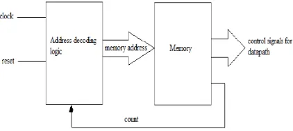
The architecture of the data path unit can be classified as sequential and parallel depending upon the method adopted for computing output signal. The architecture of data path completely depends on the nature of application. Typically it consists of multipliers, adders, data registers and multiplexers. Data registers acts as a memory to hold input signal and filter coefficients for computing. Multiplexer are used to route the appropriate data to multipliers in accordance with (2). Two approaches can be adopted for designing control unit, hardwired and micro-programmed. Micro-programmed control unit stores the microinstructions inside the memory that can be fetched using address decoding logic. These microinstructions generate the control signals for data path unit. The main advantage of the micro-programmed control unit is its flexibility to modify the micro-program in the memory [12]. Micro-programmed control unit consist of address decoding logic and memory. Fig. 5 shows the simplified block diagram of micro-programmed control unit.
ISSN(Online): 2319-8753 ISSN (Print): 2347-6710
I
nternational
J
ournal of
I
nnovative
R
esearch in
S
cience,
E
ngineering and
T
echnology
(A High Impact Factor & UGC Approved Journal)
Website: www.ijirset.com
Vol. 6, Issue 9, September 2017
The control signals from micro-programmed control unit are fed to data path unit that performs necessary operations such as load data registers with input signal and filter coefficients, perform multiplication on appropriate data, addition and latch output signal. The microinstruction also has a bit to indicate address decoding logic to stop or continue generating memory address signal.
IV. IMPLEMENTATION OF MICRO-PROGRAMMED PARALLEL FIR FILTER
The 16 x 16 bit Baugh Wooley multiplier with 18 pipelined stages implemented using fully synchronous logic and globally asynchronous locally synchronous using clock divider and decoder module given in [10] is used in the implementation of micro-programmed parallel FIR filter. GALS parallel 4-tap FIR filter that consist GALS 16-bit pipelined Baugh Wooley multipliers, carry look ahead adder and GALS micro-programmed control unit is implemented. For fair benchmarking synchronous parallel 4-tap FIR filter that consist synchronous 16-bit pipelined Baugh Wooley multipliers, carry look ahead adder and synchronous micro-programmed control unit is also implemented using same FPGA and almost same logic cells.
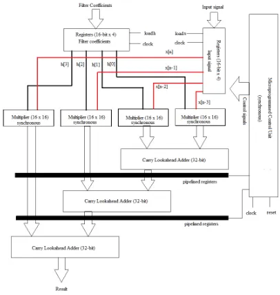
A. Synchronous Micro-programmed FIR Filter
Fig. 6 illustrates the block diagram of synchronous microprogrammed4-tap FIR filter. It consists of synchronous pipelined Baugh Wooley multiplier, carry look ahead adder, synchronous micro-programmed control unit and data registers to hold input signal and filter coefficients. All the registers, multipliers and control unit are clocked simultaneously by global clock signal. Pipelined Baugh Wooley 16-bit multiplier requires 18 pipelined stages therefore it takes 18 clock cycles to generate output. Four (4) clock cycles are required to load data into both registers simultaneously. Finally two (2) clock cycles at the adder stages are required to achieve pipeline at each stage of FIR filter. Thus 24 clock cycles are required to generate final output of the filter. Since all the pipelined registers are clocked simultaneously at higher clock rate, considerable amount of power is dissipated in the circuit.
ISSN(Online): 2319-8753 ISSN (Print): 2347-6710
I
nternational
J
ournal of
I
nnovative
R
esearch in
S
cience,
E
ngineering and
T
echnology
(A High Impact Factor & UGC Approved Journal)
Website: www.ijirset.com
Vol. 6, Issue 9, September 2017
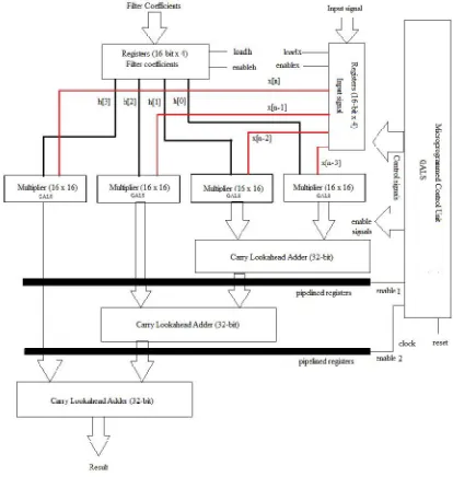
B. GALS Micro-programmed FIR Filter
Fig. 7 illustrates the block diagram of GALS micro-programmed 4-tap FIR filter. It consists of GALS pipelined Baugh Wooley multiplier, carry look ahead adder, GALS micro programmed control unit and data registers to hold input signal and filter coefficients. All the registers, multipliers and control unit are not clocked simultaneously by global clock signal. GALS micro programmed control unit receives a global clock signal that generates enable signals for all the pipelined stages and memory. On reception of the enable signal, memory generates various control signals to load data into the registers. Enable signals to the multiplier and pipelined stages at adder facilitate to perform operation in (2) to generate output. Since the global clock signal is applied only to the control unit termed as locally synchronous, while each subblocks of the FIR filter are not synchronized termed as globally asynchronous. The enable signals generated by the control unit are at much lower rate as compared to global clock rate, therefore the switching power dissipation reduces without affecting the speed of operation in GALS FIR filter.
Fig. 7 GALS micro-programmed 4-tap FIR filter Table 3 Results
V. RESULTS & DISCUSSION
ISSN(Online): 2319-8753 ISSN (Print): 2347-6710
I
nternational
J
ournal of
I
nnovative
R
esearch in
S
cience,
E
ngineering and
T
echnology
(A High Impact Factor & UGC Approved Journal)
Website: www.ijirset.com
Vol. 6, Issue 9, September 2017
5 FPGAs are a programmable alternative to custom ASIC technology [13]. The 16 x 16 bit fully synchronous and GALS pipelined MAC unit is coded in VHDL and implemented in virtex 5 FPGA (xc5vlx20t-2ff323) device. The obtained results are also confirmed on other FPGA devices such as Spartan 5
vertex 6, and Spartan 6.The output of the each block of FIR filter verified using Xilinx ISE web pack 13.1 simulation and synthesis tool. Table III summarizes the result obtained after simulation and implementation of synchronous and GALS FIR filter. Results clearly indicate that fully synchronous FIR Filter dissipates 5.26 times more power as compared to GALS FIR filter. But at the cost of increased area GALS FIR Filter requires 1.046 times more number of slices LUT as compared to fully synchronous FIR filter.
VI. CONCLUSION
The fully synchronous and GALS pipelined micro programmed FIR filter coded in VHDL and implemented in vertex 5 FPGA (xc5vlx20t-2ff323) device. The primary objective is to demonstrate low power implementation of micro programmed parallel GALS FIR filter for digital signal processing applications. Fully synchronous micro-programmed parallel FIR filter and GALS micro-programmed FIR filter are implemented using same FPGA and almost same logic cells for fair benchmarking. Results clearly indicate that fully synchronous FIR filter dissipates 5.26 times more power as compared to GALS FIR filter. But at the cost of increased area GALS FIR filter requires 1.046 times more number of slices LUT as compared to fully synchronous FIR filter. GALS micro-programmed FIR filter can be used as basic building block in GALS implementation of digital signal processor.
REFERENCES
[1]. Semiconductor Industry Association, “International Technology Roadmap for Semiconductors,” http://www.itrs.net.
[2]. L. A. Plana et al., “A GALS infrastructure for a massively parallel multiprocessor,” IEEE Design and Test of Computers, vol. 24, no. 5, pp. 454– 463, Sep.–Oct. 2007.
[3]. S. Dasgupta and A. Yakovlev, “Comparative analysis of GALS clocking schemes,” IET Computer &DigitalTechonolgy, vol. 1, no. 2, pp. 59–69, Mar. 2007.
[4]. Kwen-Siong Chong, et al, “Synchronous-Logic and Globally-Asynchronous-Locally-Synchronous (GALS) Acoustic Digital SignalProcessors”, IEEE Journal Of Solid-State Circuits, vol. 47, no. 3, pp 769 – 780, March 2012.
[5]. R.Dobkin, R. Ginosar, and C. P. Sotiriou, “Data synchronization issues in GALS SoCs,” in Proc. Int. Symp. Async. Circuits Syst. (ASYNC), pp. 170–179, 2004.
[6]. V. K. Ingle, J. G. Proakis, “Digital Signal Processing using Matlab”, in 2nd Edition, Cengage Learning, 2007.
[7]. Uwe Beyer Baese, “Digital Signal Processing using Field Programmable Gate Array”, in Springer Series on Signal & Communication Technology, 2007.
[8]. Clive Max Maxfield, “The Design Warrior’s Guide to FPGAs,” Elsevier Publication, 2006.
[9]. GouriWazurkar, S. L. Badjate, “Power Efficient GALS Pipelined MAC Unit for FFT with Complex Numbers”, in IEEE International Conference on Signal Processing, Communication, Power and Embedded System (SCOPES), 2016.
[10]. GouriWazurkar, S. L. Badjate, “Globally Asynchronous Locally Synchronous (GALS) Pipelined Signed Multiplier”, in IEEE International Conference on Computing, Analytics and Security Trends (CAST), 2016.
[11]. R. C. Baugh and A. B. Wooley, “A two’s complement parallel array multiplication algorithm,” IEEE Trans. Computers, Vol. C-22, No. 12, pp. 1045-1047, Dec. 1973.
[12]. Syed ManzoorQasim and Mohammed S. BenSaleh, “Hardware Implementationof MicroprogrammedControllerBased Digital FIR Filter”, in Springer IAENG Transactions onEngineering Technologies, 2012.