Abstract
JOSHI, SANDESH SURENDRA. Drilling Parameters and Their Effect on Chip Clogging and Surface Roughness. (Under the direction of Dr. James B. Taylor.)
In the woodworking industry, drilling (boring) is one of the most extensively used
processes. Due to the traditional nature of the woodworking industry, not much data on
machining has been recorded, only a fraction of this on drilling. This lack of information
hinders the understanding and thus improvement in the process of drilling. The objective
of this research is to provide a pilot study on chip clogging and the surface finish
generated while drilling wood and also to examine the surface breakout at the point of
drill entry and exit while drilling. This will help the industry by giving an insight into the
drilling of wood for furthering research in focused areas. Experiments on chip clogging
were carried out with two sizes of standard twist drills and the effect of feed (in/rev),
spindle speed (rpm), passage of air jet, pecking cycle and rotational tool were studied on
chip clogging. For the study of surface finish, a full factorial experimental design was
implemented to evaluate the effect of factor level combinations of four wood types, four
drill types, grain directions (along and across the grain), spindle speed (rpm) and feed
(in/rev) and their interactions with respect to the surface quality of the machined
workpiece. These 128 factor level combinations were replicated three times for a total of
384 experiments. The data obtained was statistically tested by using the analysis of
variance techniques to prove the level of significance for each factor and interaction with
investigation for the benefit of the industry. Results on the surface finish study show
trends in the behavior of parameters and future work should include developing
mathematical models for accurately predicting responses with respect to the input
Drilling Parameters and Their Effect on Chip
Clogging and Surface Roughness
by
SANDESH SURENDRA JOSHI
A thesis submitted to the Graduate Faculty of
North Carolina State University
in partial fulfillment of the
requirements for the degree of
Master of Science
Industrial Engineering
Raleigh, NC
1999
APPROVED BY
_____________________
___________________
Dr. Denis Cormier
Dr. Thomas Honeycutt
____________________________
Dr. James B. Taylor
PERSONAL BIBLIOGRAPHY
Sandesh Joshi was born on July 26th, 1977 in Pune, India. He did his schooling at Bal
Shikshan Mandir followed by high school at S. P. College, Pune. After schooling, he
joined the Indian Institute of Technology, Bombay (IIT B) in July 1994 for further
education. After graduating from IIT, Bombay with a degree of Bachelor of Technology
(B.Tech) in Mechanical Engineering, Sandesh moved to North Carolina State University,
Raleigh, USA for graduate studies in August, 1998. After completion of his Master’s
degree in Industrial Engineering, he plans to work in industry and looks forward to an
ACKNOWLEDGEMENTS
The author would like to express deepest gratitude to his advisor, Dr. James B. Taylor for
his continuous encouragement, support and invaluable guidance throughout the course of
this research project. He would also like to thank Mr. Richard Lemaster for always being
there to help him out of small and big problems and would also like to thank his
committee members, Dr. Denis Cormier and Dr. Thomas Honeycutt for their enthusiastic
involvement and being on his committee.
Also, thanks to Jason Low, Kapil Gupta, Andres Carrano and Brian for lending him a
helping hand and also for being nice friends.
Thanks to his roommates Rajeev Prabhakar and Amit Khandelwal for just being his
roommates.
Finally, the author expresses thanks to his family for their support and for always
TABLE OF CONTENTS
LIST OF FIGURES vi
LIST OF TABLES viii
1
Introduction
1
1.1 Statement of Objectives 2
1.2 Methodology 3
2
Literature Review
4
2.1 The wood 4
2.2 Wood machining 18
2.3 Wood boring 32
2.4 Wood boring drill bits 36
3
Experimentation
39
3.1 Overview of the experiments 39
3.2 Experiments with chip clogging 39
3.3 Experiments with surface finish of drilled holes 43
3.4 Experiments with surface breakout for drill entry and exit 46
3.5 Equipment and materials 47
3.6 Experimental design 58
4
Results and Analysis
68
4.1 Chip clogging 68
4.2 Surface roughness 72
4.3 Surface breakout for drill entry and exit 86
5
Conclusions and Future Work
92
5.1 Chip clogging 92
5.2 Surface roughness 93
5.3 Surface breakout at drill entry and exit 94
5.4 Future work 95
6
References
97
7
Appendices
100
7.1 Description of wood types 101
7.2 Measurement of moisture content 104
7.3 Surface roughness measurement 105
7.4 Experimental data 109
7.5 ANOVAS 111
LIST OF FIGURES
Fig 2.1: Shrinkage curves for wood [Panshin et. al., 1970] 9
Fig 2.2: Limit of moisture content of wood with a given specific gravity [Koehler,
1924]
13
Fig 2.3: Moisture content of wood vs. relative humidity of air [Koehler, 1924] 13
Fig 2.4: Geometry showing 90° - θ° orthogonal cutting 20
Fig 2.5: Schematic drawing of failure Type I(a) 22
Fig 2.6: Schematic drawing of failure Type I(b) 22
Fig 2.7: Schematic drawing of failure Type II(a) 23
Fig 2.8: Schematic drawing of failure Type II(b) 23
Fig 2.9: One beam model [McKenzie, 1960] 25
Fig 2.10: Schematic representation of the variation of friction coefficient with
speed
31
Fig 2.11: Effect of moisture content on Thrust [McMillin et. al., 1972] 33
Fig 2.12: Effect of moisture content on Torque [McMillin et. al., 1972] 34
Fig 2.13: Drill bits used for this study 38
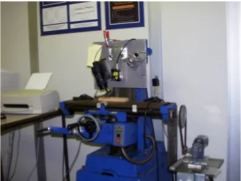
Fig 3.1: Cincinnati Milacron CNC vertical machining center (VMC) 49
Fig 3.2: Drilling setup on VMC while experiments in progress 50
Fig 3.3: Cincinnati Milacron CNC turning center 52
Fig 3.5: Laser surface roughness measurement setup used in this study 54
Fig 3.6: Schematic drawing of the working principle of the surface quality
assessment system (Microtrak 250)
54
Fig 3.7: Moisture meter used in this study (Delmhorst, model RDM-15) 55
Fig 3.8: Specimens kept in conditioning room (Hodges Laboratory, NCSU) 57
Fig 3.9: Drill bits used in the study 57
Fig 3.10: Experimental tree for chip clogging experiments 61
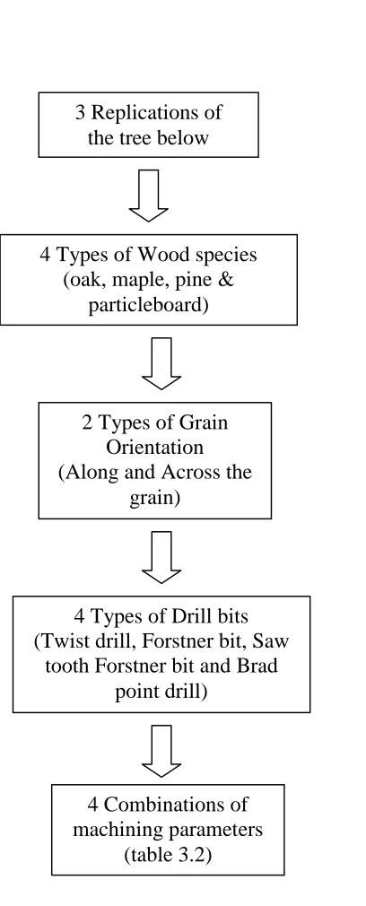
Fig 3.11 Experimental tree for surface roughness experiments 62
Fig 3.12 Experimental Tree for quantification of surface breakout at the point of
entry and exit of drill bit while drilling particleboard
63
Fig 4.1: Comparison of drilling of two wood species with respect to chip clogging 69
Fig 4.2: Results of chip clogging experiments 70
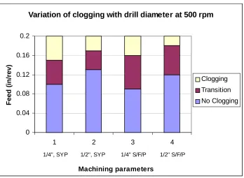
Fig 4.3: Effect of drill diameter on chip clogging 71
Fig 4.4: Plots of surface roughness against drills and grain direction 84
Fig 4.5: Plots of surface roughness against feed and speed 85
Fig 4.6: Plot of surface roughness against wood types 86
Fig 4.7: Plot of surface breakout against drill type 90
Fig 4.8: Plots of surface breakout against feed (in/rev) and speed (rpm) 91
Fig 5.1: Figure of surface damage around the hole while drilling particleboard 95
Fig 7.1: Calculation of Surface Roughness Average Ra 107
LIST OF TABLES
Table 2.1: Surface grading rules [Clark et. al., 1987] 16
Table 2.2: Surface grading rules [Clark et. al., 1987] 16
Table 3.1: Weights of three samples of each wood type for seven weeks 56
Table 3.2: Combinations of machining parameters used for experimentation 60
Table 4.1: Codes used for representing the parameters used in the study 73
Table 4.2: Coded settings of experimental factors 73
Table 4.3: Experimental results with respect to surface roughness for oak (Rq in
µm)
74
Table 4.4: Experimental results with respect to surface roughness for maple (Rq in
µm)
75
Table 4.5: Experimental results with respect to surface roughness for pine (Rq in
µm)
76
Table 4.6: Experimental results with respect to surface roughness for particleboard
(Rq in µm)
77
Table 4.7: Effect of grain direction while drilling oak with drill 2 with respect to
Rq
79
Table 4.8: Statistical significance of factors and interactions with respect to
surface roughness
82
Table 4.9: Average surface roughness values for the combination of important
parameters used in the experiments (Rq µm)
83
Table 4.10: Experimental Results with respect to surface breakout for drill entry
and exit (particleboard)
88
Table 4.12: Statistical significance of factors and their interactions with respect to
surface damage for drill entry and exit
90
Table 7.1: Surface roughness measurements (Rq in µm) 109
Table 7.2: Surface damage measurements while drilling particleboard at the points
of drill entry and exit
110
Table 7.3: Statistical significance of experimental parameters at α = 0.05 with
respect to surface roughness
111
Table 7.4: Statistical significance of experimental parameters at α = 0.01 with
respect to surface roughness
113
Table 7.5: Statistical significance of experimental parameters at α = 0.05 with
respect to entry and exit of drill
115
Table 7.6: Statistical significance of experimental parameters at α = 0.01 with
respect to entry and exit of drill
1. Introduction
Since the early days of civilization, society’s progress has been closely associated with
man’s dependence on wood. In prehistoric times, man relied on wood for survival,
shelter, making weapons, and for fire to cook his food and warm himself (Panshin A. J.,
et. al., 1970). Later, he used wood for transportation by making wheels and boats to move
around. The greater the technological advances, the more diverse and sophisticated the
uses man has found for wood. Even though a variety of materials are available today,
wood is extensively used for furniture making, wood-pulp products, house-building and
many other less readily recognizable items such as transparent films, filaments and
fabrics, plastics and chemicals, to list a few.
Traditionally, wood has been the most commonly used material in the furniture industry.
Due to its ease of shaping, wood found its way into man’s society. Typically, furniture
was manufactured by shaping wood by hand. The industrial age has provided machines to
aid in furniture manufacturing.
Since man’s dependence on wood is of such antiquity it is only natural that an extensive
empirical background on its uses should have been accumulated. But, because of heavy
reliance on working traditionally, it is not surprising to find that even today, though some
of the information on wood is factual, much of it is colored with prejudice or is distorted
by the rule-of-thumb approach. Its reason may be attributed to the extreme versatility of
wood, coupled with its almost universal availability to men of different cultures and
degrees of technical attainment.
The versatility of wood as a raw material is due to its structure, properties and chemical
composition. Wood is available in a variety of grain patterns within the same species or
even for the same tree [Tsoumis G., 1968]. Wood also has a high strength to weight ratio.
It can be relatively easily worked with tools and machines. Yet, wood also possesses
certain undesirable properties. It may burn or decay. Burning is important when
loss of strength with time after a product has been manufactured to specifications. It is
hygroscopic and hence absorbs liquids and swells. This prevents use of liquids (for e.g.
coolants) while working with wood. The properties of wood are hence dependant on the
grain structure as well as the moisture content, which makes it difficult to understand and
work with.
The properties of wood combined with the traditional tendency of working with wood
based on the rule of thumb has led to not much documentation on scientific data
regarding wood machining, although, more and more work is being published regarding
woodworking in recent times.
McKenzie [1960] has studied the wood cutting process and analyzed the chip formation
process in detail. His work provides insight into the wood-tool interaction during wood
machining. He also proposed a model for chip formation during wood machining. Mote
et. al. [1962] also worked on cutting mechanisms in wood machining and analyzed the
stress distribution in wood ahead of the cutting tool. Koch [1955] worked extensively on
planning of wood.
There is, however, very little literature available on drilling or boring of wood. Wood
drilling is a complex process and hence, it is difficult to extrapolate the results of wood
machining processes like knife cutting to drilling, e.g., in drilling, the grain direction with
respect to the cutting edge is not constant.
1.1 Statement of objectives
Further work in the field of wood machining needs concrete scientific understanding of
various machining processes used in the industry. This project is an effort to analyze
drilling (boring) of wood with respect to machining parameters, chip clogging and the
resulting surface roughness using four types of drill bits commonly used in the
woodworking industry. The study also looks at the surface breakout at the point of drill
The work on this project may be split into three parts. The first part comprised evaluating
chip clogging while drilling wood under various machining parameters for different types
of wood. It was also aimed to test the use of “through air jet” for reducing chip clogging
in wood drilling.
The second part of the project was aimed at studying the effect of machining parameters
(feed (in/rev) and speed (rpm)), grain direction, wood types and drill geometry on the
surface roughness of drilled hole.
The third part of the project aimed at quantifying surface breakout at the point of drill
entry and exit while drilling particleboard.
1.2 Methodology
The study started with a literature review to examine the previous work in this field,
wood machining in general and to identify the scope of this project. This included a
review of classic literature on wood science and furniture making industry, as well as
review of papers on wood machining. With this background, objectives were formulated
based on the necessities of the wood machining industry.
The second stage involved the design of experiments to accomplish the objectives that
were formulated. This included preliminary a study of the drilling process and parameters
and identifying outputs of interest. This was accomplished by running the experimental
setup for preliminary runs to constrain the range of parameters to be varied.
The third stage comprised the actual experimental setup and performance of the
experiments. Once the parameters to be varied were defined as well as constrained,
experiments were conducted at all factor levels of the parameters and the output data
analyzed for results. Finally, the last stage comprised drawing conclusions and making
2 Literature Review
2.1 The wood
From a practical standpoint, not all plants can be commercially used as wood. Thus,
often, plants are often classified into woody and non-woody plants to distinguish between
plants that can be used as wood and others that cannot. A woody plant may be defined as
a perennial plant reaching a height of at least twenty feet and producing a trunk of
sufficient diameter to be of value in the production of wood products [Spencer et. al.,
1975]. From a botanist’s perspective, woody plants must be vascular plants, i.e., they
must possess specialized conducting tissues consisting of xylem (wood) and phloem
(inner bark) [Panshin et. al., 1970]. The xylem is lignified and is the wood of the mature
plant. Thus plants devoid of vascular tissue cannot produce wood. Typical woody plants
exhibit the capability of thickening their stems by increasing the diameter. This is
accomplished by growing a new layer, called Cambium, every year between the last
formed layer of wood and beneath the inner bark. The growth rate of the new layer
around the stem is usually high during the start of the (spring) season and the growth rate
decreases appreciably as the season advances. Thus, the earlywood, also termed as
springwood, is conspicuously porous, while latewood, also termed as summerwood, is
dense as well as dark compared to springwood.
2.1.1 Classification of trees
Anatomically, trees are classified within the division Spermatophytes (seed bearing
plants). Depending on the manner in which the seeds are borne, Spermatophytes are in
turn sub-divided into Angiosperms and Gymnosperms. Hardwoods are included in the
class Angiospermae, derived from the Greek word for “enclosed seed”, while softwoods
fall in the gymnospermae class, derived from Greek word for “naked seed”. Amongst the
includes most of the commercially useful softwoods. Angiosperms are further classified
into two sub-classes of Monocotyledonae and Dicotyledonae. Hardwoods of commercial
importance belong to the sub-class Dicotyledonae.
Angiosperms, fruit and nut-bearing plants, are also termed as deciduous woods (meaning
“leaf losing”). Hardwood does not necessarily refer to the hardness or texture of wood
and is often misleading. The aesthetic value and physical properties of hardwoods make
them an important constituent of furniture manufacturing industry. Most important
hardwoods include ash, basswood, beech, birch, cherry, elm, gum, hickory, mahogany,
maple, oak and walnut among others. Gymnosperms are classified as softwoods and have
needle-like leaves. Softwoods, similar to hardwoods is a misleading name since some
softwoods are in fact harder than hardwoods. Softwoods are more commonly used for
pulp and paper industry, building materials and some furniture. Common commercially
used softwoods include cedar, bald cypress, spruce, fir, pine and redwood.
2.1.2 Physical properties of wood
Weight of wood: Typically, utilization, strength, beauty, workability and durability of wood are more important factors than its weight. However, the weight of wood directly
affects the material handling as well as its transportation costs. Furthermore, the weight
of the wood indirectly indicates the strength, shrinkage and some other properties of the
wood. The weight of wood [Koehler, 1924] can be attributed to:
1. Density or the actual amount of cell walls of the wood
2. Moisture content
3. Amount of mineral matter or ash
4. Resin, pitch or other non-mineral substances that are not part of cell wall
there is a large variation in the weight of dry wood even within the same species of wood
depending on its density. In a cross-section of mature trees, the outer portion is often
lighter than the portion nearer to the center. Another factor that affects the variation in
weight is the moisture content. The weight of wood is often designated as the weight per
cubic feet of wood at a given moisture content.
Specific gravity [Panshin et. al., 1970]: Specific gravity is expressed as a ratio of the weight of the substance to the weight of an equal volume of water and is abbreviated as
sp gr or G.
sp gr = (Oven dry weight of wood)/(weight of displaced volume of water)
The value of the denominator varies with the moisture content of wood. Thus, the
minimum value of specific gravity is obtained, when the green volume is used, and the
maximum when the wood is at the oven dry condition, in determining the weight of
displaced volume of water. Specific gravity based on green volume is also termed as
basic specific gravity since it is nearly constant and reproducible and is hence commonly
cited.
In general, the specific gravity of wood depends upon (1) the size of the cells, (2) the
thickness of the cell walls, and (3) the interrelationship between the number of cells of
various kinds in terms of (1) and (2). For example; if the fibers are thick-walled and show
small lumina, then the total air space is relatively small, and the specific gravity tends to
be high and vice-versa. Woods with specific gravities of 0.36 or less are considered to be
light; from 0.36 to 0.50, moderately light to moderately heavy; and above 0.50, heavy.
Density: Density of homogeneous material is defined as its mass per unit volume:
ρ = mass/volume
Density of dry solid cell wall material in the ovendry condition is found out to be
variation in this value with different wood species. The density of the actual cell wall is
believed to be similar to that of the solid cell wall substance when both are measured at
oven dry condition. With increasing moisture content of wood below the fiber saturation
point, the microcavities in the cell walls increase in volume, thus reducing the density
below that of solid cell wall substance. This ratio of cell wall density to dry solid cell wall
density is termed as packing fraction.
Weight density for wood is defined as the weight of wood per unit volume. The minimum
values for weight densities are attained at oven dry condition and the maximum when
wood is fully saturated. Thus,
Wt. density of wood = (wt. of wood with moisture)/(volume of wood with moisture)
Grain and texture of wood: In the wood industry, the words “grain” and “texture of wood” are often interchangeably used and are not rigidly defined. One can infer about the
grain and texture of wood by visually inspecting the specimen. So, for example; the term
coarse grain is used for wood with large pores, such as oak, mahogany, etc. On the
contrary, wood types with small elements, such as gum, yellow poplar and white pine are
classified as fine grained or close grained. Lumber that shows little contrast between
springwood and summerwood, as in spruce and white pine, are classified as even grain
lumber. Uneven grain applies to lumber in which summerwood is conspicuous and harder
to work, as in oak. Rough and smooth grain refers to the character of the surface after
finishing. Whether the wood is rough or smooth grained depends partly on the size and
direction of the wood elements and on the tendency of the fibers to stand out of the
surface while finishing, producing woolly grain or fuzzy grain.
The word “grain” is also used to reflect the direction of fibers in a wood specimen. So,
straight grain means that the fibers in tree trunks and timber products run practically
parallel to the main axis. Spiral grain indicates that the fibers go spirally along the trunk
giving it a twisted appearance. Diagonal grain is produced when straight grained timber
and can be seen in a radial cross section of wood. Curly grain is an irregular distortion of
fibers. If the curly grain structure produces aesthetic figured forms, it is termed as
landscape grain.
Hardness: Hardness of wood is the measure of its resistance to indentation. It also signifies its resistance to wear and tear while in use. Typically, hardness is measured by
pressing a steel ball into wood using a specific load. Wood exhibits similar hardness
values along the radial and tangential direction. However, end hardness is consistently
greater than side hardness. Commercially, filler material such as molten high-grade rosin
or paraffin is artificially impregnated into absolutely dry wood to increase hardness of
wood.
Shrinkage and swelling: Wood exhibits variation in dimensions mainly due to the change in moisture content. While the wood dries, the movement of moisture is not the
same in all the directions with respect to the major axes in wood. In the longitudinal
direction, the movement of water in the vapor form is greatly expedited by the tubular
structure of the cells. As a consequence, water moves about 12 to 15 times faster along
the grain than it does across it. This also affects the dimensional changes in wood while it
dries.
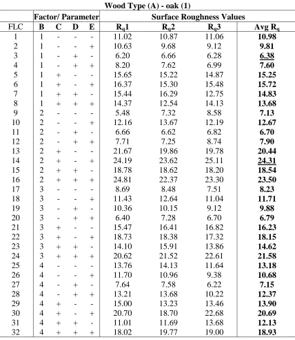
Figure 2.1 shows the dimensional variation of wood with moisture content. These curves
are typical for all woods although these curves have been generated for a limited number
of woods and levels of moisture content. It can be observed that tangential shrinkage for
air-dried wood is about twice as large as radial shrinkage at the same moisture content.
Volumetric shrinkage is approximately the sum of the radial and tangential shrinkage as
the longitudinal shrinkage is almost negligible, being in the order of 0.1% to 0.2%. Also,
the curves between 6 to 18% moisture content are approximately straight lines and hence
the dimensional change between these moisture contents can be assumed to have a linear
The experiments have indicated that the total sorption of water by dry wood may be
considered as the sum of the sorption of individual constituents of a cell [Youngs, 1961].
Slightly less than one half of the sorption is due to cellulose; about three-eighths is due to
hemi-cellulose and one-eighth due to lignin. Work on other species has indicated that
between one-third and one half of the total sorption is due to hemi-cellulose. Other
aspects of the relationship of sorption to chemical and morphological constituents have
also been explored.
Fig 2.1: Shrinkage curves for wood [Panshin et. al. 1970]
% Shrinkage = (change of dimension from swollen size) /(Swollen size) * 100
2.1.3 Mechanical properties of wood
Compressive strength: Compressive Strength is a measure of pressure along the direction of grain a specimen can withstand. Compressive strength is important for beams
or blocks that may be used to support loads. Compressive strength varies with moisture
content of wood. For example; perfectly dry red spruce without any defects may sustain 0
2 4 6 8 10 12
0 5 10 15 20 25
Moisture Content, %
D
imensional change,
%
Volumetric
Tangential
Radial
up to four times the load of the green piece [Tiemann]. However, character of failure also
varies with moisture content. A dry piece of wood fails suddenly and collapses while a
green piece gives way slowly in compression, fibers bending and buckling on themselves.
Stiffness: Stiffness is a measure of resistance offered by wood while deflecting (bending) up to a proportional limit. Proportional limit is the point at which the deflection is no
longer directly proportional to the stress or applied load. Stiffness also indicates the
capability of wooden beams to absorb shocks without permanent damage. Stiffness of
wood is sensitive to temperature, which is often exploited to bend wooden sticks into
furniture [Tiemann]. When a wooden stick is heated and moistened, it can be bent into
desired shapes without damaging the wood and the stick regain its stiffness and strength
when redried.
Toughness or fatigue strength: Toughness is a measure of the capability of wood to endure oscillating stress. The number of oscillations (cycles) of stress a specimen will
stand depends upon the load applied at each oscillation or the amount deflected and the
rapidity (frequency) of change of stress. In a fatigue test, during the oscillations, the
stress may or may not change direction and it is an important parameter in the test.
Mechanical properties of wood haven’t yet been completely studied. However, the trends
in strength values of a single piece of wood are approximately known. Thus, the greatest
load will be sustained by wood under the following conditions: kiln-dry, cold, loaded for
a brief interval of time, not subjected to vibration or reversal stresses. On the contrary,
wood will fail most readily if it is saturated, hot, under a dead load for a long time and
subjected to vibrations. Izod impact strength of several wood species showed a
maximum, depending on species, in the vicinity of 20 to 25% moisture content and
2.1.4 Factors affecting properties of wood
1. Moisture content: The moisture content of wood is usually expressed as the percentage of oven dry weight of wood. Thus 35% moisture based on oven dry weight
means that the water in wood weighs 35% of the oven dry weight of wood. The moisture
content of wood is measured as follows. A section, measuring not more than 1 inch with
the grain, is cut out across the piece at least 2 feet from the end, unless the piece is less
than 4 feet, in which case, the section is cut out of the middle portion of the wood. All
loose slivers are trimmed off and the section weighed carefully. The piece is then dried in
an oven to completely get rid of moisture. When the section has attained a constant
weight, it is considered to be oven dry. The total loss in weight represents the amount of
moisture in the wood, unless it contains volatile oils. Using this weight difference and the
original weight of the wood piece, percentage moisture in wood can be calculated.
There is often variation in moisture content in wood even within the same tree, e.g.,
typically, the moisture content is relatively higher in top logs as compared to bottom logs
since top logs are composed mainly of sapwood. The moisture content in green wood
(non-dry) wood often varies with months of a year.
According to Tiemann, there is a maximum amount of moisture that wood of any specific
gravity can hold. The curve in figure 2.2 shows this relationship. Since wood shrinks and
swells due to variation in moisture content, seasoning of wood before machining is very
important or else the end product may deform after processing due to gain or loss of
moisture. Under ordinary conditions, wood will absorb or give off moisture until a
balance is reached when no further change will take place. This moisture content is
termed as the Equilibrium Moisture Content (EMC). At first, the rate of change of
moisture content is quite high but decreases as it approaches equilibrium moisture
content. At equilibrium, there is a definite relationship between the moisture content of
wood and the relative humidity of air. This relationship is shown by the curves in the
down to about 6% moisture content with respect to oven dry weight of wood where it
reaches equilibrium with the surroundings. This relationship is approximately the same
for all the woods irrespective of species.
2. Defects in wood: Most defects in wood adversely affect its service value and hence understanding the defects in wood is very important. They can be classified as natural
and artificial defects. Like all living organisms, trees as well exhibit abnormal growth
patterns and defects as they grow. Defects in wood also arise from its processing, e.g.,
incorrect sawing and seasoning are artificial defects.
Some of the important natural defects in wood may be enumerated as follows [Tsoumis,
1968]:
(a) Spiral grain: Spiral grain is due to the spiral arrangement of wood cells in relation to
the stem axis. This defect may affect the strength of wood considerably depending on
the angle of deviation. Spiral grain also affects the dimensional stability and finishing
characteristics of wood.
(b) Abnormal arrangement of growth rings: Even if wood doesn’t exhibit spiral grain, its
cross section might disclose anomalies pertaining to growth rings such as deviations
from normal growth rings and double or multi-pith formation. Eccentricity is often
caused by one-sided development of the crown that results in a better nutrition of one
side of the stem. Apart from eccentric arrangement of rings and the resulting unequal
width, eccentricity is often associated with production of reaction wood. False rings
form in response to environmental influences that cause intraseasonal disturbances of
growth with the result that more than one growth ring is laid down during a single
growing season. False rings cause cellular deviations. In softwood, false rings mainly
0 50 100 150 200 250 300
0 0.5 1 1.5 2
Specific gravity based on dry w eight and green volume = S
P
e
rcent moisture based on dry w
e
ight
Fig 2.2: Limit of moisture content of wood with a given specific gravity [Koehler, 1924]
Fig 2.3: Moisture content of wood vs. relative humidity of air [Koehler, 1924]
0 5 10 15 20 25 30 35 40
0 10 20 30 40 50 60 70 80 90 100
Relative humidity of atmosphere, %
E
quilibr
ium moistur
e
content,
%
70 F
141 F
number and diameter of vessels and other cell elements. Discontinuous rings, by
definition, are rings that do not complete a circle around the pith. In general, False
rings and discontinuous rings do not adversely affect the service value of wood.
Another form of defect arises when the rings are indented, and hence the name
indented rings. Indented rings are more common in softwoods at high elevations than
otherwise.
(c) Reaction wood: Sometimes, the tree shows local compression and tension in wood
and the combined effect is termed as Reaction Wood. Compression wood is
conspicuously darker than the surrounding wood and is mainly composed of late
(summer) wood. Tension wood is not as easy to identify as compression wood is.
Tension wood is generally denser, shinier and lighter in color than the surrounding
wood. Reaction wood also affects the properties of wood, e.g.; Compression wood has
higher specific gravity and longitudinal shrinkage coefficient and also exhibits erratic
strength. Compression wood has relatively low stiffness, bending strength and
toughness for its weight and breaks with characteristic brash failures. Tension wood
also exhibits higher specific gravity and longitudinal shrinkage coefficient than
normal wood. Tension wood causes warping, corrugations and checks in veneer.
While machining tension wood, saws become overheated and pinched, developing
“woolly grain” along the surfaces sawn longitudinally. Typically, reaction wood is
associated with eccentric rings and compression wood occurs on the lower side
(which is under compression) and tension wood on the upper side (which is under
tension).
(d) Knots: Knot is an inclusion of basal part of the branch within the stem of a tree. Knot
free wood is only produced in the lower portion of the stem, where the branches fall
off naturally or are pruned artificially. If dead branches are enclosed in a stem, the
knots produced are termed as loose or encased, since such knots are loose and may
fall off during processing of wood for its end use. If living branches are enclosed in
through continuous growth rings and are termed as intergrown or tight knots. Knots
adversely affect the appearance as well as properties of wood due to its abnormal
structure, higher density of its wood and also due to the association of knots with
grain deviation and checks. Strength of wood may be reduce due to presence of knots
depending on their kind, size and location and on the loading type. However, induced
natural or artificial pruning in trees may help control the degree of knotiness in wood.
(e) Pith: Although pith is an essential part of a living tree, its undesirable properties make
it an undesirable part of the end product. The different cellular structure of the pith in
comparison to the surrounding wood reduces both its strength and durability. Also,
wood immediately around the pith often contains small checks and knots of various
sizes.
Since defects in wood can adversely affect the mechanical and physical properties of
wood and hence its end use, it is important to understand the “goodness” of a wood
sample and hence its limitations of end use. For ease of knowing the “goodness” of
wood, wood is graded according to the number of defects in a wood sample and the
fraction of defect-free surface area. American Lumber Standards has laid down
classifications, nomenclature, basic grades, sizes, description, measurement, tally,
shipping provisions, grade marking and inspection of softwood lumber according to
detailed specifications. According to American Lumber Standards, lumber is classified as
to use, size and stage of manufacture. Based on use, there are yard lumber, structural
material and factory or shop lumber with grading rules adapted to each. Various grade
associations have different grading rules.
In general, softwood is graded for use of the whole board without cutting, the finish
grades for appearance and common board grades for strength. Table 2.1 and table 2.2
Table 2.1: Surface grading rules [Clark et. al., 1987]
Grade Allows
B & Better Finish
About two to three small defects on best surface of board
#1 Boards Any number of sound knots if under 2” in diameter for boards 6” or
8” wide
#2 Boards Any number of knots if under 3” in diameter in boards 6” wide and 3 ½” in diameter in boards 8” wide
#3 Boards Knots larger than those allowed on #2 boards and knot holes if
smaller than one quarter the width of the board
2.1.5 Lumber conditioning
2.1.5.1 Saw-milling
There are two common methods of performing saw milling: plain or flat sawn and quarter
sawn.
• Plain or flat sawn: Produces a full width edge and squared up boards with the annual rings in a series of contour markings. Boards cut in this way are known as tangential
cut.
Table 2.2: Surface grading rules [Clark et. al., 1987]
Grade Contains
First and Seconds (FAS) 83-1/3 to 91-1/3% clear face cuttings
#1 Common 66-2/3 to 83-2/3% clear face cuttings
#2 Common 50 to 66-2/3% clear face cuttings
#3A Common 33-1/3 to 50% clear face cuttings
• Quarter sawn: In this cut the boards have the annual rings running in a perfect radial fashion along the longitudinal axis of the board. Few quarter-sawn boards are
obtained from the traditional way of cutting and usually a special order has to be
placed in order to purchase a significant quantity of them.
2.1.5.2 Seasoning of wood
It is not uncommon for freshly cut timber to have a moisture content of 100% based upon
the absolute dry weight of the wood sample. As soon as the tree is felled, the moisture
content starts falling as the water in the vessels starts evaporating immediately. Once
these vessels dry up, the rate of decrease of moisture content slows down as the water
present in the fibers does not evaporate so easily (fiber saturation point is reached). The
wood after felling starts losing its water till it reaches equilibrium with the ambient
conditions or till it reaches the Equilibrium Moisture Content (EMC).
Seasoning is the process of speeding up loss of moisture in wood so as to reach
Equilibrium Moisture Content fast. It is desirable that wood should be used after
seasoning, as seasoning tends to improve strength, stiffness and hardness of timber,
greatly reduces weight and renders it less likely to shrink in subsequent usage. Also,
seasoned timber is less susceptible to decay than green wood.
Traditionally, the wood would be seasoned by “Air-drying” [Kellogg, 1931]. In this
process, wooden planks or specimens are stacked together in open air such that there is
enough ventilation. Depending upon atmospheric conditions, the wood then takes a few
months to a year for seasoning. Thus, this is a very time consuming process and depends
on the unpredictable climatic conditions.
An improved version of air-drying process is to keep wood specimens in a controlled
environment. Thus, wood is kept in a conditioning room that is maintained at specific
temperature and humidity. As shown in figure 2.3, there is a definite relationship between
Seasoning of wood in such an environment takes a few weeks depending upon the
starting moisture content of wood. This process was used in the project for seasoning the
specimens to approximately 6% moisture content (EMC).
A faster method for seasoning wood is to season wood by kiln drying. In kiln drying,
additional heat is applied. This process takes relatively shorter time as compared to other
processes. The time required is typically in days instead of weeks or months. In kiln
drying, it is important to control the humidity, temperature and air circulation so as not to
produce uneven evaporation leading to defects, such as warpage.
2.2 Wood machining
Not much literature is available directly on boring (drilling) of wood and hence along
with some literature on drilling, the literature on knife cutting and planing of wood has
also been presented below, which may be relevantly extrapolated to boring of wood as
well.
2.2.1 Wood and its cutting properties:
Wood is cellular in nature and this considerably affects its behavior in the region of the
cutter edge. Also, the cutter is not ideally sharp. In practice, the edge radius of sharp
cutters is 2.0 to 2.5 microns, while the double cell wall thickness ranges 2 to 15 microns,
that is, they are no more than 10 times as great. Thus, the edge in meeting a cell wall does
not impose such a concentrated load as might otherwise be thought. Due to this, the cell
wall deflects considerably before it fails [McKenzie, 1962].
McKenzie [1960] has described fundamental aspects of wood cutting processes and
analyzed the various chip formation modes in wood cutting and put forth a single beam
and double beam model to explain woodcutting. Earlier, Franz [1958] also classified chip
Since wood has anisotropic properties due to the conspicuous grain structure, it is
important to note the orientation of a wood specimen being machined. Most of the
literature refers to orthogonal cutting, which is used as a standard notation for wood
machining. It would be relevant at this point to briefly define and understand orthogonal
cutting.
2.2.1.1 Orthogonal cutting
In orthogonal cutting, the cutter has a straight edge wider than the workpiece and
perpendicular to the velocity vector and moves with uniform velocity in a plane parallel
to the newly generated surface of the work-piece. Orthogonal cutting situation can be
specified by the angles made respectively by the cutting edge and cutting velocity vector
with the grain direction of the wood. In orthogonal cutting, the grain angle is given by the
notation 90°-θ, where, 90° is the angle between the cutter edge and the longitudinal grain
direction and θ, also termed as cutting angle, is the included angle between the velocity
vector and the longitudinal grain direction as shown in figure 2.4
2.2.2 McKenzie’s model to explain cutting in wood
2.2.2.1 Wood failure types while machining
The majority of wood machining problems generally concern the situations where a
single cutter, of variable shape, takes a variable path through a workpiece at a variable
speed and at a variable angle of the grain. Further, this cutting process can be regarded as
a sequence of separate actions, as is noted by Reineke [1950], and these may be
distinguished as (a) chip severance and (b) chip break up and removal.
McKenzie [1960] has broadly classified wood chip failures (severance) into two main
types with two subtypes within each type of failure. He observed that at cutting angles
below 20 degrees, cutting is too irregular to be classified; deflections are high and wood
1. Chip failure Type I
Splits occur along the grain below the cutting plane while cutting force remains constant.
In Type I(a) failure, short but regular splits occur that may be associated with small
wavelength and amplitude of the recorded cutting forces, and the resultant surface quality
Fig: 2.4: Geometry showing 90°-θ orthogonal cutting 90°
Tool
Graindirection Workpiece
Velocity Vector
Grain Direction
θ
Cutting Plane
Tool
Workpiece
Top View
is comparatively good. In Type I(b) failure, 2-3 or more short splits occur between
regularly spaced longer splits. In both cases, after the first cut, the spacing and length of
the split remain essentially the same, which account for regularity of the average cutting
forces in successive cuts. Above the cutting plane, each subchip is formed by shear along
the grain simultaneously as a split forms below. In cuts after the first, the subchips are
loosely linked continuously in Type I(a), but in Type I(b), they are in groups
corresponding to the spacing of major splits. The failures Type I(a) and Type I(b) are
shown in figure 2.5 and figure 2.6 schematically.
2. Chip failure Type II
This type of failure is associated with a cyclic variation of average cutting forces with
successive cuts. Failures occur in a plane perpendicular to the grain and parallel to the
cutting plane at a variable distance below it. They may be intermittent (Type II(a)) or
continuous (Type II(b)). In Type II(a), severance at the cutting plane takes place,
accompanied by shearing above forming subchips so that the broken end of the lamina
remains in place to be removed by the next one or two cuts. In Type II(b), severance
occurs continuously along a plane parallel to the cutting plane. The chip above the cutting
plane may be sheared into subchips or remain intact so that two continuous chips are
formed, one above and one below the cutting plane. The failures Type II(a) and Type
II(b) are shown in figure 2.7 and figure 2.8 schematically.
2.2.2.2 Factors affecting wood chip failure
Moisture Content: In saturated wood, the predominant failure type is I(a) with slight
splitting, and low steady cutting forces. For 5% moisture content, the failures below the
cutting plane are always deeper than the normal chip thickness, and the predominant
failure type is type II.
Cutting Angles (θ): At cutting angles below about 20 degrees, irregular types of failures
depending on moisture content and density. Severance at cutting edge produces a
continuous chip in either case. Cutting force increases and the normal force on the cutter
changes from negative (into the work piece) to positive (away from workpiece) with
decreasing cutting angle.
Fig 2.5: Schematic drawing of failure Type I(a)
Fig 2.6: Schematic drawing of failure Type I(b)
Tool
Workpiece
Fig 2.7: Schematic diagram of Failure Type II(a)
Fig 2.8: Schematic diagram of Failure Type II(b)
Tool
Workpiece
Chip Thickness: With increasing chip thickness, usual trend is to move from Type I(a) to
Type II(a) for all saturated woods and low to medium-density species, and from
crumbling action to Type II(b) failure in dense species.
2.2.2.3 One-beam model
After analyzing his experimental results, McKenzie [1960] proposed a one-beam model
to analytically explain failure of wood while cutting. Figure 2.9 illustrates the model
based on the concept of a semi-infinite beam, the lower end of which is embedded in a
foundation whose depth is large compared to that of the beam. The observations then
confirm that the failure type is independent of cutting angle and chip thickness over a
wide range. Instead, it depends on the ratio of maximum bending stress to modulus of
rupture. Wherever the maximum bending stress is below the modulus of rupture, failure
is of Type I and when the modulus of rupture is below the maximum bending stress,
failure is of Type II. When the two values are close (as in case of eastern white pine),
both failures may occur in different parts of the cut. These results are observed for cutting
angles between 30 to 40 degrees and chip thickness between 0.010 to 0.030 inch. At a
chip thickness below 0.010 inch, Type II failure is less likely and above 0.050 inch, Type
II failure is more likely. Bending stress is inturn dependent on the ratio of modulus of
elasticity perpendicular and parallel to the grain.
Improving upon his one beam model, McKenzie [1962] also proposed a revised
two-beam model, which is an attempt to model woodcutting over a range of cutting properties
of timber and over a range of moisture content and cutting conditions. He developed
theoretical relationships between cutting forces, the nature of the chip and cut surface, the
physical and mechanical properties of the wood and the cutting geometry. This model is
Fig 2.9: One beam model [McKenzie, 1960]
2.2.3 Wood chip failure types according to Franz [1958]:
Stewart [1971] indicated that chipped grain occurs within a small range of grain angles
(upto 20°) when cutting against the grain at rake angles greater than 20 degrees, and that
chipped grain could be prevented with optimum combinations of lower rake angles and
depths of cut. Machining defects are produced when machining against the grain and
rarely when machining along the grain.
Franz [1958] has classified wood chips into 3 categories:
Type I: Formed when the wood splits ahead of the tool by cleavage and fails as a
cantilever beam in bending.
Type II: Formed when the wood chip fails along an inclined plane extending from
the cutting edge to the surface of the work.
Beam Shear Plane
Type III: Formed when tool forces cause failures in the wood ahead of the cutting
edge.
Type I chip is formed when the indentation of the cutting tool causes a cleavage
failure. Type II chip is formed if a shear plane develops at an angle to the grain. A Type
III chip is formed if compression and shear failures develop at and ahead of the tool edge.
He observed that an increase in grain angle increases the chip thickness.
As grain angle (θ, figure 2.4) is increased, compression ahead of the tool edge becomes
increasingly prominent and a Type III chip failure results regardless of depth of cut. With
a decrease of rake angle the cleavage failure is greatly reduced, and a Type I chip failure
that results in chipped grain is prevented. As the grain angle increases, the high
compressive forces, characteristic of low rake angles, tend to accentuate the indentation
phase.
It has been observed that optimum surface roughness generally coincides with the
formation of Type II chip failure when machining against the grain [Stewart, 1971].
Stewart’s [1971] extensive work with white ash shows that Type III chip is predominant
at grain angles greater than 20° and abrupt transition occurs amongst the three chip
failure types at grain angles less than 20°. Chipped grain results from the formation of a
Type I chip when machining against the grain. Type I chip failure is formed when the
chip, acting as a cantilever beam, is cleaved from the workpiece. The amount of chipped
grain depends on the extent of the cleavage failure along the grain. An increase of grain
angle increases the effective thickness of the undeformed chip, which continues to act as
a cantilever beam. The thicker the chip, the stiffer it becomes, and the less readily it
separates from the workpiece. Thus as the grain angle increases, the tool loses its wedge
effect between the wood fibers. Chipped grain is not formed at grain angles greater than
As the grain angle is varied from 0° through 90° to 180°, the cutting forces parallel to the
cutting plane show less fluctuation as compared to the cutting forces perpendicular to the
cutting plane. As the cutting direction is oriented to larger grain angles, the wood fibers
are bent or folded over ahead of the tool edge. This deflection of wood fibers causes the
tool to cut more perpendicular to the grain when cutting against the grain. Therefore a
steep increase of the parallel cutting tool force may result from the tool acting in
compression perpendicular to the grain as well as the increased stiffness of the chip
acting as a cantilever beam.
2.2.4 Factors affecting wood machining
1. Cutting speed
Lin’s [1965] experiments with Douglas-fir and redwood confirmed that surface finish
improves with increasing cutting speed, although not much. Cutting speed while
machining wood is also limited at times by the excess heat generated by cutting at high
speeds and thus the possibility of damaging the wood.
2. Rake angle
Rake angle plays a significant role in determining the chipped grain and hence the surface
quality of the machined wood surface [Stewart 1970]. Stewart [1970] sampled with 10°,
15°, 20° and 25° rake angles for various wood species. He showed that, for hardwoods,
knives with rake angles of 20° or less are advisable for reduced chipped grain and hence
better surface finish. Results from other wood species might show similar trends as well
and hence this trend in rake angle may be used as a rule of thumb.
3. Depth of cut
Stewart [1970] experimented with depth of cut on the occurrence of chipped grain and
found that up to a certain depth of cut (about 1/16th inch), the occurrence of chipped grain
rule of thumb that the thinner the depth of cut the better the surface quality. If the depth
of cut is very small (typically less than 1/16th inch), chipped grain is independent of rake
angle of the tool. Hence, shallower depths of cut might ensure better surface finish.
However, as grain angle increases, surface finish of machined wood deteriorates with
excessively shallow depth of cut.
4. Cutting forces
It has been observed that that dense summerwood crushes the less dense springwood
during the planning process [Stewart et. al. 1982]. Another study shows that raised grain
results from crushing of wood cells of the surface and immediate subsurface layers
during knife cutting or sanding. These deformed cells then swell when exposed to
swelling agents such as water and causes raised grain. Since forces that develop during
machining cause crushing, machining situations that reduce these forces should reduce
the extent of crushing below the surface.
It has been observed that the main cutting resistance does not change much with cutting
speeds in the cases of smaller depths of cut and larger rake angles, but it does change
remarkably under the combination of a larger depth of cut and smaller rake angle [Mori
et. al., 1979].
Machining across the grain requires less power than machining along the grain, which in
turn implies that severity of crushing during knife planning is less after planning across
the grain than along the grain.
It is observed that lower density wood is crushed more extensively below the surface than
is the higher density wood for the same machining conditions. Thus, density (directly
related to hardness) and compression strength (related to the proportional limit strength)
are indices of resistance to indentation, and may serve as indicators of relative subsurface
deformation to be expected in different workpieces subjected to similar machining
plane surface, but the surface would deform (fuzz) on the application of water borne
finishing agents or exposure to moisture.
5. Effect of cutting speed on cutting Forces
In practice, a higher cutting speed is almost always accompanied by the cutting of a
thinner chip, so that the cutting forces and surface damage are both reduced. Liska [1950]
found that the strength of compression parallel to the grain and flexure increased 8
percent for every 10-fold increase in testing speed up to 24 inch/minute. Koch [1955-56]
also suggests that change in momentum of chips may account for increased tool forces,
although its contribution has been later observed to be negligible. Practically, it has been
observed that cutting forces decrease with an increase in cutting speed. This can be
ascribed to an initial decrease of the friction coefficient and also due to the increased
temperature, which reduces the strength. Thus, an increase in cutting forces due to
increased strain rate (Maxwell effect) is being opposed by a decrease due to higher
temperature and possibly reduced friction. Unfortunately, no data regarding surface
quality was recorded by McKenzie [1960] for the above experiment.
6. Cutting using vibration
It was thought that the basic effect of lateral motion might be used to accomplish
severance of cell walls without excessive compression. McKenzie [1960] achieved lateral
relative motion between the workpiece and the cutter by means of a solenoid with a 60
Hz frequency. This has pronounced effect on chip formation. All failure types are
replaced by Type I(a) with very little delamination. The surface generated shows only
fine splits on the cut surface, and the fraying of the edges characteristic of cutting in this
direction was practically absent. The lateral vibrations increase the effective cutting angle
7. The frictional behavior of wood
Frictional behavior of wood is critical in understanding the mechanism of the machining
processes as it determines the interaction between the tool and wood and hence
influences the parameters like cutting force, cutting speed and the heat generated while
machining. Intermittent sliding and stick-slip oscillations were especially prevalent with
the apparatus used in earlier work. McKenzie et. al., [1968] observed surface roughness
of wood and its temperature have a very small effect on the frictional behavior of wood
and hence can be neglected.
In extracted air-dry wood, the sliding is virtually “dry” and the classical laws of friction
may be expected to hold. It is believed that the frictional effect is due to welding or
adhesion at relatively few points of the nominal interface. Experiments on friction
between stainless steel and solvent extracted wood shows that the adhesion is by
hydrogen bonding between the hydroxyl groups of the wood substance and the oxide
layer on the steel surface. However these bonds do not form readily under some
conditions. Possibly Van der Waals’ forces also contribute.
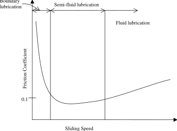
Typically, in lubricated sliding, the friction coefficient decreases to a minimum with
increasing sliding speed before it starts increasing again as shown in figure 2.10. It is
noted that the speed at which the minimum occurs, and its level, increases with surface
roughness. Also, with increasing viscosity of the lubricant, the minimum occurs at a
higher speed and a lower frictional coefficient. The variation of the frictional coefficient
with species of wood is not much as compared to other factors like moisture content and
surface (smooth or rough). The variation of content and nature of lipids (a greasy
constituent of wood) does not greatly affect the friction coefficient except under critical
conditions, that is, at certain combinations of moisture content, steel roughness and
sliding speed.
Fiber direction affects the incidence and amplitude of stick-slip oscillation. Results also
on rough steel. The effect of roughness of wood is slight except for roughness values less
than 50 microns, in which region there is a steep rise with increasing roughness. For most
practical purposes, it may be summed up that for most air-dry wood sliding on steel has a
friction coefficient of 0.4 to 0.6. As against wet wood, for steady sliding of air-dry
extracted wood, the frictional behavior is virtually independent of speed and steel
roughness. On rough steel at slow speed, the value for wet wood is practically equal to
that for dry wood, presumably because hydrodynamic effects are small. However, at
higher speeds these effects reduce the value for frictional coefficient of wet wood
[McKenzie et. al., 1968].
Fig. 2.10: Schematic representation of the variation of friction coefficient with speed.
In case of wood sliding on wood, the resulting trend is intermediate between the curves
for normal woods on smooth and rough steel, but closer to that for rough steel.
0.1
Semi-fluid lubrication Boundary
lubrication
Fluid lubrication
Sliding Speed
Friction C
o
efficien
2.3 Wood boring
2.3.1 Effect of moisture content on thrust, torque and chip formation
McMillin et. al. [1972] extensively studied the effect of moisture content in southern pine
as related to thrust, torque and chip formation while boring. Boring can be carried out in
3 directions: Longitudinal, Tangential and Radial with respect to grain direction. It was
observed that the thrust is lower and torque is higher in the longitudinal direction than in
either tangential or radial direction. Also, thrust and torque in the tangential and radial
directions are not significantly different and hence they may be grouped together as
across the grain while longitudinal direction is termed as along the grain. For both
drilling directions, thrust rose to a maximum in wood of about 5 % moisture content,
decreased rapidly to a minimum at about 30% moisture and then remained relatively
constant [McKenzie et. al., 1972] as shown in figure 2.11 and figure 2.12.
When cutting along the longitudinal direction, the action of lips (the cutting edges
generating the chips) approximate orthogonal cutting across the grain. Examination of the
particles produced at zero and 10 percent moisture content indicate that Franz Type I
chips are generally formed when the lips were cutting in the planing direction. The chips
generated at zero percent moisture are considerably shorter and less curled than those
produced at 10%. At 80% moisture, chips similar to Franz Type II are most frequently
formed. Failures of the cantilever beam type are generally observed when cutting in the
veneer direction up to 10% moisture content. Failure occurs closer to the cutting edge for
wood at 0% than at 10% moisture
2.3.2 Chip clogging and grain direction
McMillin et. al. [1972] studied and compared drilling deep holes in southern pine with a
ship auger bit and a double-spur double-twist machine bit. It was observed that clogging
consistently occurs at a shallower depth when boring across the grain than when boring
speed when chip thickness is held constant. Also, thrust and torque were lower when
boring with the ship auger than with machine bit.
Fig. 2.11: Effect of moisture content on thrust [McMillin et. al., 1972]
The quality of holes does not differ between various specific gravities, chip thickness, or
spindle speeds. However, significant differences are detected between moisture contents
and bit types. In quality of holes bored along the grain, the ship auger excelled in dry
wood but was not significantly better than the machine bit in wet wood. Across the grain,
the machine drill bit yields better holes in both wet and dry wood.
80 60
40 20
180
160
140
120
100
80
Along the grain Across the grain
Moisture content, %
Thrus
t (po
unds
When boring a deep hole, operators commonly retract the bit to clear chips from the
flutes and then advance it for a further cut (also termed as “pecking cycle”). Clogging
occurs at a shallower depth (about 6.5 inch) when boring across the grain than along the
grain (10.1-inch). McMillin et. al. [1972] observed that there is no significant difference
between the performance of bit types with respect to chip clogging irrespective of the
grain direction.
Fig. 2.12: Effect of moisture content on torque [McMillin et. al., 1972]
Chips generated by boring across the grain remain relatively intact, while those generated
along the grain are fragmented and small. Intact chips are more difficult to exhaust from
32
80 60
40 20
52
48
44
40
36
Along the grain
Across the grain
Moisture content, %
Torque
(i
nch
-po
unds
the hole and are more likely to clog the flutes. It can be inferred that bits should be
retracted from the work about every 6 inches when boring across the grain, while 10-inch
deep holes can be cut in a single plunge along the grain for southern pine.
2.3.3 Komatsu’s experiments on machine boring properties of wood
It was observed [Komatsu, 1976] that the performance of a drill with respect to the
surface finish and roundness of the hole is dependant on spindle speed and there exist a
range of spindle speeds for each drill geometry in which the drill performs the best for a
wood species. Komatsu observed that a Japanese boring bit performs the best in the range
of 1500 to 2500 rpm. It was also observed that a spur machine bit yields smoother and
more concentric holes as compared to a twist drill. He also observed that the torque and
thrust while drilling can be expressed as an exponential function of feed speed. The
relationship between torque (T) and thrust (P) and feed (F) is shown in equations 2.1 and
2.2.
T = a Fb …(eq. 2.1)
P = c Fd …(eq. 2.2)
where;
a, b, c and d = constants dependant on actual boring conditions and wood species
Komatsu [1978] observed in his experiments that boring properties are similar for drilling
wood along the tangential or radial section. He observed that the thrust force has higher
values while drilling along the grain than drilling across the grain at all moisture content
levels. However, the amplitude of thrust has a lowest value for drilling along the grain.
Thrust and torque show a maximum value at the moisture content of 5-20%.
Komatsu’s [1979] experiments with drilling wood indicated that the torque values show a
Amplitude of thrust indicated the smallest value at a grain angle of 90° and the largest at
a grain angle of 30° at which the average value of thrust was the smallest. Thrust was
observed to reach a maximum at a grain angle of 90°. For soft and medium density
hardwood, thrust does not increase much above grain angles of 60° and for high density
hardwood, thrust does not increase much above grain angles of 45°. Experiments also
show that the accuracy of a hole bored with a twist drill depends on the amplitude of the
cutting force.
2.4 Wood boring drill bits
With mechanization of wood working, initially, machine tools used for metal working
were also used for wood working and hence, the most common metal working drill, the
standard twist drill has been used in wood drilling for quite a long time now. However,
apart from twist drill, other types of drills are also used, viz., brad point drill, Forstner bit
drill, saw tooth Forstner bit drill, auger drill, power bore, spoon drill bit, etc. Amongst the
above mentioned drill bits, the more common drill bits used in the industry include brad
point drill bit, Forstner bit drill, saw tooth Forstner bit drill and also the standard twist
drill. Each of these drill bits have different applications depending on their specific
advantages and disadvantages. Whatever the geometry of the drill, a drill must perform
the following: (1) stay centered; (2) cut the wood loose to form a round hole; (3) eject the
chips. The following sections discuss the characteristics of drill bits commonly used in
the industry. Figure 2.13 shows a saw tooth Forstner bit drill, Forstner bit drill, standard
twist drill and brad point drill from left to right respectively.
Standard twist drill
It is one of the most common as well as the simplest drill bit used in the industry. It
covers the widest range of cutting possibilities in wood, sheet goods, metals and plastics
and is available in a variety of sizes [Boggs, 1999]. In general, twist drills performs well
![Fig 2.1: Shrinkage curves for wood [Panshin et. al. 1970]](https://thumb-us.123doks.com/thumbv2/123dok_us/1365031.1169280/20.612.135.446.252.460/fig-shrinkage-curves-wood-panshin-et-al.webp)