A MATRIX INVERSION HARDWARE ARCHITECTURE BASED ON GAUSS-JORDAN ELIMINATION FOR MIMO APPLICATIONS.
HAMMAM ORABI
A project report submitted in partial fulfilment of the requirements for the award of the degree of
Master of Engineering (Electrical-Electronics and Telecommunications)
Faculty of Electrical Engineering Universiti Teknologi Malaysia
iii
To Father, Mother, Brothers, Sisters, Sidra,
Friends,
iv
ACKNOWLEDGEMENT
I would like to start by expressing my sincere appreciation to my supervisor, Dr. Rabia Bakhteri who did not withhold any effort in supporting me by help, advice, and guidance throughout both of the project’s phases; Research Project Proposal and Project Thesis.
v
ABSTRACT
vi
ABSTRAK
vii
TABLE OF CONTENTS
CHAPTER TITLE PAGE
DECLARATION ii
DEDICATION iii
ACKNOWLEDGEMENT iv
ABSTRACT v
ABSTRAK vi
TABLE OF CONTENTS vii
LIST OF TABLES x
LIST OF FIGURES xi
LIST OF SYMBOLS xiii
LIST OF APPENDICES xiv
1 INTRODUCTION
1.1 Project Background 1
1.2 Problem Statement 4
1.3 Objective 5
1.4 Scope 6
1.5 Project Overview 7
1.6 Thesis Structure 9
2 LITERATURE REVIEW
2.1 Introduction 10
2.2 Numerical Methods for Matrix Inversion 10
viii
2.4 Row Pivoting 14
2.5 Gauss-Jordan Elimination 15
2.6 Comparison between Different Methods 16
2.7 Previous works 17
2.7.1 FPGA Implementation Of Floating-Point Complex Matrix Inversion Based On Gauss-Jordan Elimination (Moussa et al., 2013)
17
2.7.2 On the Design of an On-line Complex Ma-trix Inversion Unit (McIlenny and Ercego-vac, 2005)
18
2.7.3 A Suitable FPGA Implementation Of Float-ing-Point Matrix Inversion Based On Gauss-Jordan Elimination (Jacobi et al.,
2011)
18
2.8 Summary 19
3 METHODOLOGY
3.1 Introduction 20
3.2 Design Life Cycle 20
3.3 Project Flow 23
3.4 Data Path Modules for Real Numbers 24
3.4.1 Pivoting 26
3.4.2 Memory Address Generator 26
3.4.3 Normalization 30
3.4.4 Elimination 32
3.5 Control Unit 35
3.6 Extension for Complex Numbers 36
3.7 Optimization for Speed 38
3.7.1 Optimized Modules for Real Numbers 40 3.7.2 Optimized Modules for Complex Numbers 43
3.8 Summary 43
4 RESULTS AND DISCUSSION
4.1 Introduction 45
ix
4.2.1 Look Up Tables 46
4.2.2 Embedded 9-bit Multipliers 47
4.2.3 M9K units utilization 48
4.2.4 Clock cycle count 48
4.3 Comparison with Software Approach 50 4.4 Comparison with previous Hardware Architectures 51 4.4.1 Comparison with Jacobi et al. (2011) 52 4.4.2 Comparison with (Moussa et al. 2013) 52
4.5 Summary 56
5 CONCLUSION
5.1 Conclusion 57
5.2 Future Works 58
REFERENCES 59
x
LIST OF TABLES
TABLE NO. TITLE PAGE
3.1 Pivoting states and operations 27
3.2 Detailed events of pivoting operation 29
3.3 Control State Table of the CU 40
xi
LIST OF FIGURES
FIGURE NO. TITLE PAGE
1.1 MIMO-OFDM Transmitter 2
1.2 MIMO-OFDM Reciever 2
1.3 Plot of CPU time vs matrix’s size 5
1.4 Top level module of G-J 7
3.1 Development Life Cycle of the project 21
3.2 Hierarchal modular concept for G-J algorithm 22
3.3 Project’s Progress phases 23
3.4 The Data Path for HA.R.A 25
3.5 Memory Initialization File for the Mem_RAM 25
3.6 FSM of Pivoting Module 28
3.7 Functional simulation for Pivoting module 28
3.8 Functional Block Diagram of MAG unit 29
3.9 Top Level Module of Normalization module 30
3.10 Data path unit of Normalization module 31
3.11 Control Unit of Normalization module 32
3.12 Elimination top level module 33
3.13 Data path unit of Elimination module 34
3.14 FSM of Elimination CU 34
3.15 FSM of the main CU 37
3.16 Data path for the hardware architecture of complex num-bers-HA.C.A
39
3.17 Complex Divider 39
3.18 Complex Normalization Data Path Unit 41
xii
3.20 Complex Elimination Data Path Unit 42
3.21 DU of HA.R.S 42
3.22 DU of HA.C.S 44
4.1 Hardware architectures designed in this project 45 4.2 LUT utilization for different matrix sizes (HA.R.A and
HA.R.S)
46
4.3 LUT utilization for different matrix sizes (HA.C.A and HA.C.S)
47
4.4 9-bit Embedded Multipliers utilization for all HAs 47
4.5 M9K utilization for different matrix sizes 48
4.6 Clock Cycle Count for HA.R.A and HA.R.S 49
4.7 Clock Cycle Count for HA.C.A and HA.C.S 49
4.8 Total Latency for MATLAB, HA.R.A, and HA.R.S 50 4.9 Total Latency for MATLAB, HA.C.A, and HA.C.S 51 4.10 Latency comparison between Jacobi et al. (2011) and
HA.R.S
52
4.11 LUTs consumption comparison between Jacobi et al. (2011) and HA.R.S
53
4.12 LUTs consumption comparison between Moussa et al. (2013) and HA.C.A
54
4.13 Clock cycle count comparison between HA.C.S and Moussa et al. (2013)
54
4.14 Memory kinds and numbers used in our design and Moussa et al. (2013)
xiii
LIST OF SYMBOLS
G-J Gauss-Jordan
HA Hardware Architecture
HA.C.A Hardware Architecture for Complex Numbers optimized for Area
HA.R.A Hardware Architecture for Real Numbers optimized for Area
HA.R.S Hardware Architecture for Real Numbers optimized for Speed
HA.R.S Hardware Architecture for Complex Numbers optimized for Speed
ICI Inter Carrier Interference ISI Inter Symbol Interference MIMO Multiple input multiple output
OFDM Orthogonal Frequency Division Multiplexing
𝐻 Complex Propagation Matrix
𝑁𝑡 Number of transmitted signals
𝑁𝑡 Number of received signals
𝑊 Zero mean complex Additive White Gaussian Noise
𝑋 Transmitted symbols
xiv
LIST OF APPENDICES
APPENDIX TITLE PAGE
A - MATLAB Source Code 61
B - C Source Code 63
CHAPTER 1
INTRODUCTION
1.1 Project Background
Orthogonal Frequency Division Multiplexing (OFDM) is becoming a very popular multi-carrier modulation technique for transmission of signals over wireless channels. OFDM divides the high-rate stream into parallel lower rate data and hence prolongs the symbol duration, thus helping to eliminate Inter Symbol Interference (ISI). It also allows the bandwidth of subcarriers to overlap without Inter Carrier In-terference (ICI) as long as the modulated carriers are orthogonal. OFDM therefore is considered as an efficient modulation technique for broadband access in a very disper-sive environment.
2 M-Array Mapping Space Time Coding Pilot Insertion Pilot Insertion Pilot Insertion IDFT IDFT IDFT Add CP Add CP Add CP
X1 (k)
X2 (k)
XNT (k)
x1 (n)
x2 (n)
xNT (n) Input
Data
Figure1.1 MIMO-OFDM Transmitter
Remove CP Remove CP Remove CP DFT DFT DFT Channel Estimation Zero Forcing Reciever Dem apper y1 (n)
y2 (n)
yNT (n)
Y1 (k)
Y2 (k)
YNR (k)
Output Data Matrix Inverse H1 H2 HNT
H
H
-1Figure1.2 MIMO-OFDM Reciever
As a MIMO signaling technique, 𝑁𝑡 different signals are transmitted simulta-neously over 𝑁𝑡 × 𝑁𝑟 transmission paths, and each of those 𝑁𝑟 received signals is a combination of all the 𝑁𝑡 transmitted signals and the distorting noise. The received signal will be the convolution of the channel and the transmitted signal. After remov-ing the cyclic prefix at the receiver’s side, the output of FFT module, as the demodu-lated received signal, can be expressed in the matrix form equation as following (as-suming that the channel is static during an OFDM block):
3
Equation (1) can be further elaborated in matrix form as equation (2).
[ 𝑌1 𝑌2 𝑌3 ⋮ 𝑌𝑁𝑟] = [
𝐻1,1 𝐻1,1 ⋯ 𝐻1,𝑁𝑟
𝐻2,1 𝐻1,1 ⋯ 𝐻1,𝑁𝑟
𝐻3,1 𝐻1,1 ⋯ 𝐻1,𝑁𝑟
⋮ ⋮ ⋱ ⋮
𝐻𝑁𝑟,1 𝐻𝑁𝑟,1 ⋯ 𝐻1,𝑁𝑟][
𝑋1 𝑋2 𝑋3 ⋮ 𝑋𝑁𝑡] + [ 𝑊1 𝑊2 𝑊3 ⋮ 𝑊𝑁𝑡] (2)
Where 𝑌 is the received vector from all the 𝑁𝑡 receiver’s antennas, 𝐻 is the channel transform function (Complex Propagation Matrix), 𝑋 represents the transmit-ted symbols from all the transmitting antennas for subcarrier 𝑘, 𝑊 represents zero mean complex Additive White Gaussian Noise. The transfer function of the matrix-valued channel impulse response is given by
𝐻(𝑒𝑗2𝜋𝜃) = ∑ 𝐻
𝑙 𝐿−1
𝑙=0
𝑒−𝑗2𝜋𝑙𝜃, 0 ≤ 𝜃 < 1 (3)
The data symbols 𝑋̂ are then estimated by linear detection algorithm such as Zero Forcing and is given by:
𝑋̂ = 𝐻−1𝑌 (4)
While (4) has to be evaluated at the symbol rate, the channel inverses 𝐻−1can be pre-computed and have to be updated only when the channel changes (Borgmann, and Bölcskei, 2004).
From the numerous matrix inversion algorithms that exist, Gauss-Jordan Al-gorithm (G-J) is characterized as a simple, efficient, direct, parallelizable, and univer-sal algorithm to find the inverse of any kind of square matrices (Duarte et al., 2009). Although its higher complexity (O(n3)) in contrast to other software algorithms (e.g. Strassen (O(n2.807)) and Coppersmith-Winograd (O(n2.376)), G-J is very important for
4
G-J Elimination requires simple arithmetic operations only i.e. Addition/Sub-traction, Multiplication, and Division. In comparison, other numerical matrix inver-sion methods require more complicated operations, such as square root operation as in QR decomposition by Gram-Schmidt Orthogonalization, and sine and cosine opera-tions as in QR decomposition by Rotation (Pozrikidis, 2008).
1.2 Problem Statement
Matrix Inversion is one of the most costly computational operations to be per-formed either in software or hardware (Hanzo et al., 2010). It has vast implementa-tions in many of nowadays technologies, especially in MIMO systems such as OFDM MIMO (Moussa et al., 2013) and Long-Term Evolution (LTE) MIMO receivers to remove the effect of the channel on the received signal (Yan et al., 2010). It can be used as a pre-coding stage in OFDM MIMO in order to cancel the interference at the Base station (Cho et al., 2010).
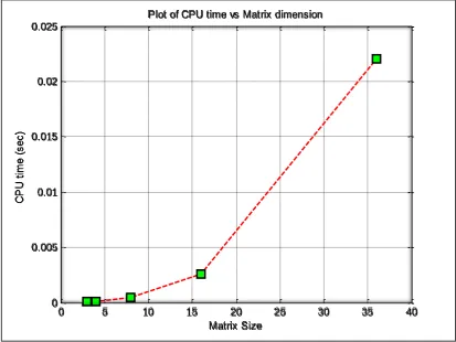
This operation is significant in MIMO systems because of its good perfor-mance in high data rates applications, as it is a straight forward concept without itera-tions (Haustein et al. 2002). Software based matrix inversion modules suffer from long latency because of the complicated decoding of the executed instruction, and be-cause of Von-Neumann bottleneck, which is a result of sharing the same memory for data and instructions. Figure 1.3 depicts the time required to perform matrix inversion on matrices of different sizes. The long latency time (0.02 second for a 36x36 matrix) makes the utilization of this technique less desirable in real time application.
5
in a system that uses such large number of subcarriers is a critical challenge of opti-mizing the design for speed and cost (Moussa et al., 2013).
On the other hand, a regular (direct) method of matrix inversion such as Cramer’s require evaluation of (𝑁 + 1) × 𝑁 × 𝑁 determents. So for a 10x10 system, 359 million multiplications have to be performed (Cho et al., 2010). For a 20x20 system the number of multiplications is factorial(21). A fast computer will do the task in 1600 years (Turner, 2000).
Figure 1.3 CPU time vs matrix’s size
0 5 10 15 20 25 30 35 40
0 0.005 0.01 0.015 0.02 0.025
Plot of CPU time vs Matrix dimension
C
P
U
t
im
e
(
s
e
c
)
6
1.3 Objective
The objective of this project is to build an accelerated, scalable, and low area cost hardware architecture that performs matrix inversion for complex numbers, using the Gauss–Jordan method. The architecture should accomplish the complex inversion in a better time than software based approaches. It should be able to operate on any matrix regardless of its size. Finally, it should achieve better area consumption in comparision to some other hardware architectures.
1.4 Scope
The proposed system is responsible for finding the inverse of the square com-plex propagation matrix in MIMO systems. Numerical computation methods are ad-dressed and compared to both numerical and regular methods.
Hardware Description Languages are the medium of implementing these algo-rithms, such as Verilog and SystemVerilog.
The following software are used in this project:
MATLAB 2013 is used for benchmarking and for results verification.
Quartus II is used for modelling the system in Verilog and SystemVer-ilog.
ModelSIM Altera is used for simulating the design and for acquiring performance statistics.
7
Single precision floating point (IEEE 745 standard) Complex Addition/Sub-traction, Multiplication and Division operations are used in the Inversion process; this is necessary since the estimated matrix has complex values.
1.5 Project Overview
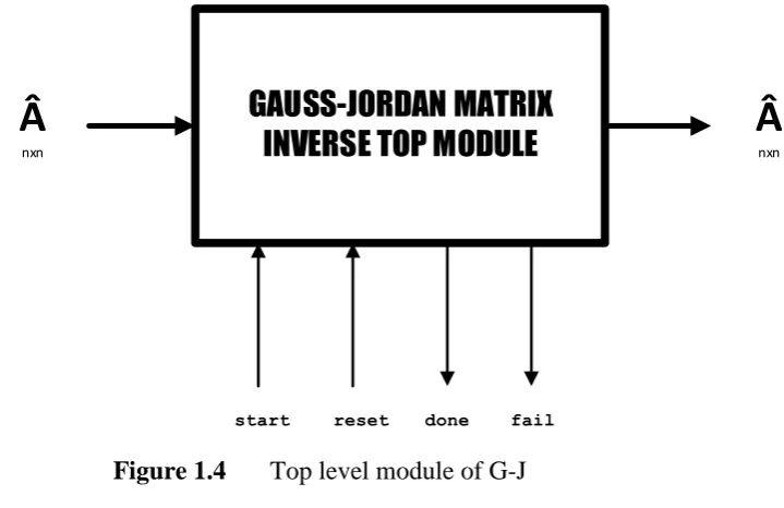
The top level functional block diagram is shown in Figure (1.4). The system will receive the complex matrix entries and find the inverse upon setting start signal high. The results will be ready after the done signal is set, while the fail signal indicates that the input matrix is a singular matrix, thus it has no inverse.
GAUSS-JORDAN MATRIX
INVERSE TOP MODULE
Â
nxn
Â
nxnstart reset done fail
Figure 1.4 Top level module of G-J
8
basic modules necessary for G-J, named: Pivoting, Normalization, Elimination, Stor-age, Memory Address Generator (MAG), and several counters designated for generat-ing the indices of the matrix’s elements. Figure (1.5) shows the CU and DU organi-zation of G-J top level module.
A tradeoff between the area cost and speed will be done, resulting in 4 different designs, 2 for each real and complex plane, each design is optimized either for speed or area requirements.
The 4 different developed designs performance will be evaluated: Real (opti-mized for area and speed) and Complex (opti(opti-mized for area and speed). The aspects of evaluation are the number of consumed clock cycles to finish the operation, latency, Look Up Tables (LUTs) consumption, M9K memory unit utilization, and RAM usage.
GAUSS JORDAN CONTROL UNIT
PIVOTING CU
NORMAILZATION CU ELIMINATION
CU
STORAGE UNIT PIVOTING
DU
NORMAILZATION DU ELIMINATION
DU
9
1.6 Thesis Structure
REFERENCES
Bagadi, K. Y., & Das, S. (2010). MIMO-OFDM Channel Estimation using Pilot Car-ries. International Journal of Computer Applications (0975 – 8887) Volume 2 – No.3, May 2010
Borgmann, M. and Bölcskei, H. (2004). Interpolation-Based Efficient Matrix Inver-sion for MIMO-OFDM Receivers. Communication Technology Laboratory, Swiss Federal Institute of Technology
Cho, Y. S., Kim, J., Yang, W. Y. and Kang, C. G. (2010). MIMO-OFDM Wireless Communications with MATLAB. John Wiley & Sons, Ltd, Chichester, UK. doi: 10.1002/9780470825631.refs
Duarte, R., Neto, H. and Vestias, M. (2009). Double-precision gauss-jordan algorithm with partial pivoting on FPGAs. 12th Euromicro Conference on, aug. 2009, pp. 273-280.
Gene H. Golub and Charles F. Van Loan (1996). Matrix computations. (3rd Edition). Johns Hopkins University Press Baltimore, MD, USA.
Hanzo, L., Akhtman, Y., Wang, L. and Jiang, M. (2010) Bibliography, in MIMO-OFDM for LTE, Wi-Fi and WiMAX, John Wiley & Sons, Ltd, Chichester, UK. doi: 10.1002/9780470711750.biblio
Haustein, T., Helmolt, C., Jorswieck, E., Jungnickel, V. and Pohl, V. (2002). Perfor-mance of MIMO systems with channel inversion. in Proc. IEEE Vehicular
Tech-nology Conference, VTC Spring, Birmingham, AL, May 2002, pp. 35–39.
60
Jacobi, R., Arias-Garcia, J., Llanos, C. and Ayala-Rincon, M. (2011). A suitable FPGA implementation of floating-point matrix inversion based on gauss-jordan elimination. VII Southern Conference on, April 2011, pp. 263-268.
Jacobi, R., Arias-Garcȋa, J., P., Llanos, C. H., & Ayala-Rincön, M. (2011). A Suitable FPGA Implementation Of Floating-Point Matrix Inversion Based On Gauss-Jor-dan Elimination.
McIlhenny, R.and Ercegovac, M. (2005). On the Design of an On-line Complex Ma-trix Inversion Unit. Proc. 39th Asilomar Conference on Signals, Systems and Computers, 5pps., 2005.
Moussa, S., Abdel Razik, A. M., Dahmane, A. O., & Hamam, H. (2013) FPGA Im-plementation Of Floating-Point Complex Matrix Inversion Based On Gauss-Jor-dan Elimination (2013). 26th IEEE Canadian Conference Of Electrical And Computer Engineering (CCECE)
Pozrikidis, C. (2008). Numerical computation in science and engineering. Oxford: Ox-ford University Press.
Senthilvelan, M. ; Iancu, D. ; Glossner, J. ; Moudgill, M. and Schulte, M. (2007). Software Solutions for Converting a MIMOOFDM Channel into
Multi-pleSISO-OFDM Channels. Third IEEE International Conference on Wireless
and Mobile Computing, Networking and Communications, 2007. WiMOB
2007.
Turner, Peter R. (2000.). Guide 2 Scientific Computing. CRC Press, 2000.
Yan, M., Feng, B. and Song, T. (2010). On Matrix Inversion for LTE MIMO Applica-tions Using Texas Instruments Floating Point DSP. Signal Processing (ICSP),