Motion Analysis of A Mobile Robot With Three Omni-Directional
Wheels
Ranjit Barua1, Sajal Mandal2 and Dr. Samiran Mandal 3 1
Mechanical Engineering Department, NITTTR-KOLKATA, Salt Lake, Sector-III, Kolkata-700106, India
2
Mechanical Engineering Department, NITTTR-KOLKATA, Salt Lake, Sector-III, Kolkata-700106, India
3
Mechanical Engineering Department, NITTTR-KOLKATA, Salt Lake, Sector-III, Kolkata-700106, India
Abstract
This paper demonstrates the kinematics motion analysis of the three wheeled omni-directional mobile robot. The mobile robot is equipped with the three omni-directional wheels which are arranged at the vertices of an equilateral triangle and the wheel axels are aligned with the lines from the center of the equilateral triangle to each of the three wheels. Model of this omni-directional wheeled robot is developed and shown the different trajectory motion of the mobile robot by controlling the DC gear motor with different combination.
Keywords: Mobile robot, Omni-directional wheel, Trajectory motion.
1.
Introduction
In modern automated industry the mobile robots are more flexible and can perform more tasks effectively. An omni-directional wheeled mobile robot is a special class of mobile robot now a days. These robot can drive along a straight line from one point to another point, while rotating along
2. Design and Development of Three Wheeled
Omni-directional Robot
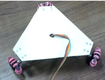
In figure 2.1, the three wheeled omni-directional robot is presented. To make this robot, the following parts are needed: a robot body frame, omni-directional wheel, DC gear motor, microcontroller, motor driver, power supply and DPDT switch.
Figure 2.1: Three wheeled omni-directional robot
motors are connected with the Arduino microcontroller through L293D motor driver. Three DPDT switches are mounted on control board to operate the robot wheels. The control board is connected with the Arduino through an eight wire bus. From the input of DPDT switch Arduino microcontroller moves the robot in the desired direction. The omni-directional wheels that provide very good manoeuvrability and enhanced mobility compared with traditional wheels. This type of wheels has small rollers to allow the wheels to move freely on any direction. They move along the primary diameter, just as any other wheel. Though, the smaller rollers along the outside of this diameter allow free rotating along an orthogonal direction to the powered rotation. The motors are coupled directly to the omni wheels simplifying the mechanics.
2.1 Kinematic model of mobile robot platform
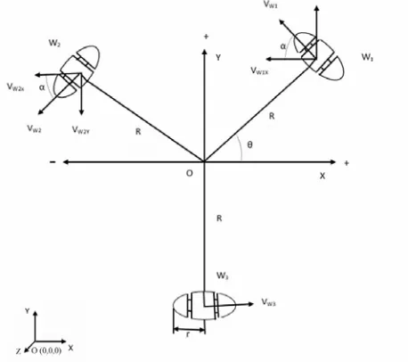
Fig.2.2 shows the schematic view of three wheeled omni-directional robot, where each wheels (W1, W2, W3) are 1200 apart, “R” is the length from robot centre mass to each wheels. VW1, VW2, VW3 are linear velocities of wheel 1, 2 and 3. ‘r’ is the radius of each omni-directional wheels. From the kinematics equation all forces are divided into two components vertically ‘Y’ axis ‘sin’ component and horizontal ‘X’ axis ‘cosine’ component.
Fig. 2.2 Schematic model of three wheeled omni-directional robot.
For wheel 1 (W1),
(4.1
VW2X = (-) VW2 Cos (α)
VW2Y = (+) VW2 Sin (α)
(4.3
)
(4.4)
VWX = VW3 – VW1 Cos(α) - VW2 Cos(α)
(4.5
)
VWY= VW1Sin(α) – VW2 Sin (α)
(4.6
)
Vθ = VW1/L + VW2/L + VW3/L
(4.7
)
VWi (1,2,3) = ω .r
(4.8
)
ω = Angular velocity of the omni-directional wheel (rad/sec).
r = Omni-directional wheel radius (cm). Vθ = Robot movement velocity.
Fig.4.2 shows the wheels are arranged in symmetrical manner 1200 apart,
So, α = 600
, put this value in equation (4.5) to (4.6),
VWX = VW3 – VW1 (1/2) - VW2(
(4.9)
VWY= VW1( – VW2 (
(4.10
)
Equations (4.7),(4.9) and (4.10) can be rewritten in matrix from:
=
(4.11
Vr=
(4.12
)
θ =
(4.13
)
where, Vwx and Vwy vectors are acts along ‘X’ and ‘Y’ direction , Vr is resultant vector.
3.Experimental Test
The experiments are done by six different combinations of
the three omni-directional wheeled robot starting points
and each combination is used three times to different tests.
When all three wheels are ON state, a tachometer is used
to measure the omni-directional wheel rotation. Same as
above procedure has followed the rest of tests i.e. one
wheel is ON in clockwise direction and two wheels are
stopped OFF, two wheels are ON in clockwise direction
and one wheel is OFF, one wheel is OFF and two wheels
are ON, three wheels are ON with one opposite direction.
A white marker/chalk is used to mark the trajectory of
above cases.
4. Results and Discussion
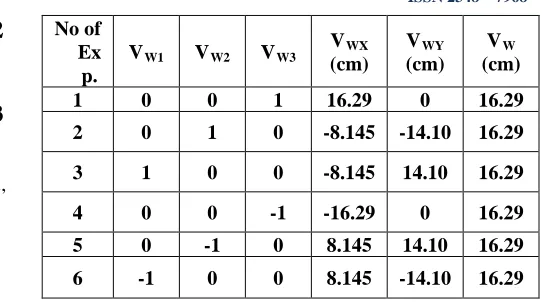
Different motions of three wheeled omni-directional robot has been studied based on six criteria. The results’ concern the velocity and direction of motion for the whole system are given in the following tables 4.1, 4.2, 4.3, 4.4, 4.5, 4.6. The inputs’ data are VW1, VW2 and VW3 which denote the wheels velocities (DC gear motor rotation) and VW is robot velocity.
Table 4.1: One wheel “ON” and Two wheels “OFF”
No of Ex
p.
VW1 VW2 VW3
VWX
(cm)
VWY
(cm) VW
(cm)
1 0 0 1 16.29 0 16.29
2 0 1 0 -8.145 -14.10 16.29
3 1 0 0 -8.145 14.10 16.29
4 0 0 -1 -16.29 0 16.29
5 0 -1 0 8.145 14.10 16.29
6 -1 0 0 8.145 -14.10 16.29
In table 4.1, when only one wheel is “ON” and two wheels are “OFF”, the three wheeled omni-directional robot have same value with different input. The direction of motion is the same as the “ON” wheel; the obtained circular path is rotation of the robot around the external centre. The maximum circular path is achieved by making tangent to the “ON” wheel
Table 4.2: Two wheels “ON” and One wheel “OFF”
No of Ex
p.
VW1 VW2 VW3
VWX
(cm)
VWY
(cm)
VW
(cm)
1 0 1 1 7.26 -12.57 14.52
2 1 1 0 -14.52 0 14.52
3 1 0 1 7.26 12.57 14.52
4 0 -1 -1 -7.26 12.57 14.52
5 -1 -1 0 14.52 0 14.52
6 -1 0 -1 -7.26 -12.57 14.52
Table 4.2 shows when two wheels is “ON” same direction and one wheel “OFF”, then the robot is make a curved path of rotation around the “OFF” wheel and the robot The minimum curved path is achieved here due to the rotation around the “OFF” wheel.
No of Ex
p.
VW1 VW2 VW3
VWX (cm) VWY (cm) VW (cm)
1 0 1 -1 -21.57 -12.47 14.35
2 0 -1 1 21.57 12.42 14.35
3 1 -1 0 0 0 14.35
4 -1 1 0 0 0 14.35
5 1 0 -1 -21.57 -12.42 14.35
6 -1 0 1 21.57 12.42 14.35
In table 4.3, when two wheels are “ON” with one of the wheel is opposite direction, thus one trying to rotate the robot clockwise and the other anticlockwise, then the robot moves in a straight line (forward motion) only with no rotation.
Table 4.4: Three wheels “ON” opposite direction No of
Ex p.
VW1 VW2 VW3 VWX
(cm) VWY
(cm) VW
(cm)
1 1 1 1 0 0 0
Table 4.5: Three wheels “ON” same direction No of
Ex p.
VW1 VW2 VW3
VWX (cm) VWY (cm) VW (cm)
1 1 1 1 0 0 0
Table 4.4 and 4.5 when all wheels are “on” in same and opposite direction the robot will rotates about its own centre of mass.
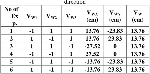
Table 4.6: Three wheels “ON” and One wheel opposite direction
No of Ex
p.
VW1 VW2 VW3 VWX
(cm)
VWY
(cm) VW
(cm)
1 -1 1 1 13.76 -23.83 13.76
2 1 -1 1 13.76 23.83 13.76
3 1 1 -1 -27.52 0 13.76
4 -1 -1 1 27.52 0 13.76
5 -1 1 -1 -13.76 -23.83 13.76 6 1 -1 -1 -13.76 23.83 13.76
In table 4.6, when the three wheels are “ON” and one wheel is opposite direction, the obtained circular path is
5. Conclusions
The model is derived assuming no wheel slip as is interesting in most standard robotic applications. By controlling motion of the three omni-directional wheels, immediate forward, backward, sideways and rotational motion, in other words, omni-directional motion is generated successfully. A mathematical kinematic model of the robot is done and velocity vector analysis each omni-directional wheel. A low-level program is created to simplify access to basic functionality of the robot. It can be easily built up with high-level algorithms for localization, trajectory planning and tracking. A straight line motion can be achieved by running two wheels only in opposite direction. The rotation of the system around its center can be obtained by running the three wheels in same direction. If the three wheels on and one of hem rotates opposite irection, the path of motion is circular.
6. Future work
The work presented is a part of vast area. Further work will include upcoming some future test with different prototypes including prototypes with braking system. The model can also be enlarged to include the limits for slippage and movement with controlled slip for the purpose of the learning traction problem. Kinematical and dynamical models are needed in this work and that can be used to study the limitations of the mechanical configuration and future enhancements of both mechanical configuration and controlling the device. This work will enable effective full comparison of three wheeled systems.
Acknowledgments
I wish to express my sincere gratitude to NITTTR-KOLKATA for providing all the necessary facilities for the research. I would like to convey my sincere gratitude to Dr. Samiran Mandal, Professor, Head Of Mechanical Engineering Department in NITTTR-KOLKATA for his valuable advices and encouragement during the project.
References
[3] Hwang, C, and Chang, L, “Trajectory Tracking and Obstacle Avoidance of Decentralized Control”,IEEE Transactions on Robotics and Automation, Vol. 12, No. 3, pp. 345-352, 2007.
[5] Chopra, N, Stipanovic, M, and Speng, M.W, “On Synchronization and Collision Avoidance for Mechanical Systems”,Journal of Robotics and Mechatronics System, Vol. 9, pp. 3713-3718, 2008.
[6] Ouhrouche, M, Chen, W.H, and Trzynadlowski, A.M, “Robust Nonlinear Predictive Controller for Permanent Magnet Synchronous Motors with an Optimized Cost Function”, IEEE Transactions on Robotics and Automation, Vol. 59, No. 7, pp. 2849-2858, 2012
[7] Ren, W, “Distributed Leaderless Consensk Algorithms for Network Euler-Lagrange System”,International Journal of Control, Vol. 82, No. 11, pp. 2137-2149, 2009.
First Author I am working as a assistant professor in OmDayal Group Of Institutions since last four months. I had completed M.Tech Mechanical Engineering (Specialized in Manufacturing Technology) from NITTTR,KOLKATA in 2015. I have always attached this kind of experimental projects in mechanical and modern manufacturing technology automation.
Second Author I had completed M.Tech Mechanical Engineering ( Specialized in Manufacturing Technology) from NITTTR,KOLKATA in 2015. I have completed my thesis work on omni-directional mobile robot.