Volume 8, No. 5, May-June 2017
International Journal of Advanced Research in Computer Science RESEARCH PAPER
Available Online at www.ijarcs.info
ISSN No. 0976-5697
A Comparative study on Linear Array Antenna Pattern Synthesis using Evolutionary
Algorithms
Jaspreet Kaur
Student,Department of Electronics and Communication Punjabi University, Patiala, Punjab (India)
Dr. Sonia Goyal
Assistant Professor,Department of Electronics and Communication Punjabi University, Patiala, Punjab
Abstract: Antenna array is defined as a collection of multiple radiating elements (antennas) which are placed in space in uniform or
non-uniform manner to get a directional radiation pattern that a single antenna generally not adequate to achieve it. In antenna array pattern side lobe level and deep nulls are major problems which cause wastage of energy. This paper presents a brief survey on previous work on optimization of the linear antenna array to achieve a radiation pattern with maximum side lobe level (SLL) reduction along with control null placement in the specified directions. To get superior ability from antenna array it is requisite to modify or synthesize its geometric configurations (as linear, circular, and rectangular etc) or its electrical parameters such as excitation amplitude, phase or distance between array elements. Modern communication system demands compact array designs with high directivity and low side lobe levels. Aimed at this problem several optimization evolutionary algorithms are presented and compared in this paper, are genetic algorithm, ant colony algorithm (ACO), modified invasive weeds optimization algorithm (MIWO), Ant Lion Optimization (ACO), Gravitational Search Algorithm (GSA) and so on.
Keywords: Micro-strip Antenna array, Side Lobe Level (SLL), Null Depth, stochastic algorithms, first null beam width (FNBW).
INTRODUCTION
Antenna, in a broad sense, refers to a basic part or back bone of the wireless communication which is utilized in short and long distance communications. It is defined by Webster's Dictionary as "a radiating device utilized to converts electronic signals to radio waves and vice versa. The antenna should be capable to radiate effectively so the power generated by the transmitter is not wasted [1]. These days widely used antenna is Micro strip patch antenna which was developed in 1970’s and after that period it becomes popular through a lot of works, especially in electromagnetic applications. One of the major advantages of micro-strip antennas is the simplicity of array construction. There are diverse application areas of antenna in wireless communication such as in cellular phones, broadcast systems, radio-frequency identification (RFID), mobile and satellite communication, military systems, missile guiding, microwave linking, remote sensing and rocket detection [2]. Antenna array synthesis is one of the most imperative electromagnetic optimization issues of current interest. These days, antenna arrays are preferred because a single antenna often failed to provide an efficient radiation characteristic such as low side lobe level and high directivity. Generally the radiation pattern of single antenna is comparatively wide, and every element provides low value of gain. Alternatively, the use of this antenna in an array makes it more efficient to achieve better response. In additional words, an antenna array comprises multiple fixed point antennas arranged in such a manner that its effective radiation pattern is interfere constructively in desired direction and cancelled in opposite direction [2]. Each of these antenna elements, while functioning has their own induction field. Therefore, the vector addition of all the individual elements radiated fields provides total field of array [3]. The primary design objective of antenna array geometry is to determine the positions of array elements that
jointly produce a radiation pattern that matches the desired pattern as closely as possible. Since, the fast increasing use of wireless communications needs an enhancement in characteristics of the network such as capacity, quality of service and coverage. An antenna array application with high directivity and low side lobe level (SLL) is an important technology that can enhance the reliability and validity of a communication system [4]. The significant role of antenna array is in detecting and processing signals arriving from different directions.
LITERATURE SURVEY
Generally, an optimum compromise between the low side lobe level and the beam width of array must be necessary, because during the side lobe level of radiation pattern is decreased, its beam width gets increased and vice versa [6].
FORMULATION OF THE DESIGN PROBLAM
The linear array is one of the most commonly used array structure. The problem considered here is to minimize the side lobe level and null placement by optimizing the antenna array parameters such as amplitude, phase and distance of the individual array elements. In our study, it is considered the geometry of an even no. of isotropic elements linear antenna array as illustrated in Fig 1. Assuming, the antenna elements are symmetric with regard to the centre of linear array [2].
Fig.1. general structure of linear antenna array [2]
The total field of an array of identical elements is equal to the field of a single element situated at the origin multiplied by a factor which is generally referred as array factor and it is independent of the antenna type. Array factor for symmetric even no. of elements array in azimuth plane can be calculated as (1)
𝐸𝐸(𝜃𝜃) = 2.∑𝑁𝑁𝑛𝑛=1𝐴𝐴𝑛𝑛𝑐𝑐𝑐𝑐𝑐𝑐[𝑘𝑘.𝑥𝑥𝑛𝑛. cos(𝜃𝜃) +𝜑𝜑𝑛𝑛] (1)
Where 𝑁𝑁 denotes the number of array elements, 𝑘𝑘 is wave
number, 𝜃𝜃 denotes azimuth angle. 𝐴𝐴𝑛𝑛, 𝜑𝜑𝑛𝑛 and 𝑥𝑥𝑛𝑛denotes the excitation amplitude, phase and location of nth array element respectively. Let us suppose that all the elements are identical and have uniform amplitude (𝐴𝐴𝑛𝑛=0) and phase excitations (𝜑𝜑𝑛𝑛 = 0), then equation (1) again simplified as (2)
𝐸𝐸(𝜃𝜃) = 2.∑𝑁𝑁𝑛𝑛=1𝐴𝐴𝑛𝑛𝑐𝑐𝑐𝑐𝑐𝑐[𝑘𝑘.𝑥𝑥𝑛𝑛. cos(𝜃𝜃)] (2)
Above equation of array factor 𝐸𝐸(𝜃𝜃) plays an important role in illustrated the characteristics of a linear antenna array. The array factor may be normalized so the normalized form of 𝐸𝐸(𝜃𝜃) is given as in dB in equation (3)
𝐸𝐸(𝜃𝜃)𝑛𝑛𝑐𝑐𝑛𝑛𝑛𝑛𝑑𝑑𝑑𝑑= 20∗ 𝑙𝑙𝑐𝑐𝑙𝑙10�𝑛𝑛𝑚𝑚𝑥𝑥𝐸𝐸(𝜃𝜃𝐸𝐸)(𝜃𝜃)� (3)
The problem of this approach is to set the proper placement
of elements is such a manner that the desired radiation pattern could be met. Thus, while formulate this problem, these conditions must be satisfied:
Minimize 𝑓𝑓=𝑛𝑛𝑚𝑚𝑛𝑛(𝐸𝐸(𝜃𝜃)𝑛𝑛𝑐𝑐𝑛𝑛𝑛𝑛𝑑𝑑𝑑𝑑)
Subject to -0.25λ<∆𝑥𝑥𝑚𝑚 < 0.25λ, 𝑚𝑚= 1, … ,𝑁𝑁, (4) With 𝑥𝑥𝑚𝑚𝑛𝑛𝑖𝑖𝑖𝑖 =𝑥𝑥𝑚𝑚0+∆𝑥𝑥𝑚𝑚
Where, 𝑓𝑓 is defined as fitness function and 𝑥𝑥𝑚𝑚 is the position of 𝑚𝑚element on x-axis. Again, the positions of elements are set in such a manner that the minimum distance between elements never less than 0.25. When the array elements place too close to one another, it actuates mutual coupling issue [7].
SIDE LOBE LEVEL MINIMIZATION IN LINEAR ANTENNA ARRAY
Side lobes are expressed as additional or unwanted lobes (maxima in other direction then major beam) outside to the main lobe in antenna array radiation pattern, which causes wastage of energy outside the significant beam. Because of the impact of side lobes, interference problem arrives at transmitting as well as reception antenna which amplifies the noise level at receiver side [8]. Therefore, the minimization of side lobe level (SLL) assures that the receiving or radiating energy to be directed in a particular direction. The side lobe level suppression is based on minimization of side lobes power. Acc. to literature, Side lobe is an imperative metric used in antenna array, which depends on position of array elements and weights. For optimal array pattern optimization, grating lobes (side lobes) appear when inter-element distance d≥ λ. So it is concluded that to avoid the side lobes in desired direction, inter-element spacing d should be <λ . Low side lobes are of importance for numerous reasons: reduction of radar and communication interrupt possibility, reduction of radar clutter and jammer susceptibility [9].
IMPLEMENTATION OF EVOLUTIONARY ALGORITHMS FOR ARRAY SYNTHESIS
Although, conventional search methods find efficient results in simple real world synthesis problems, but they may fail on large scale design problems that are nonlinear and multimodal. In this way to compensate these problems, numerous researchers have presents some evolutionary/meta-heuristic algorithms to investigate the optimum standard for array system design [8]. All meta-heuristic algorithms utilize a specific tradeoff of randomization and local search. Evolutionary algorithms are generally utilized because they have shown promising performance as better solution for some real world optimization problems close to ideal solutions, less time computation and furthermore are easy to implement on PC’s. This paper presents some well known optimization algorithms with their comparisons to each other [10].
examples are used by changing the no. of antennas as 12, 16, and 20 respectively. This synthesis includes only the amplitude excitation of antenna array elements and leaving unmodified the phase. Array factor used in this paper is described as (4)
𝐴𝐴𝐴𝐴(𝜃𝜃) = 2� 𝐼𝐼𝑛𝑛cos�(𝑛𝑛 −0.5)𝑑𝑑(𝑐𝑐𝑐𝑐𝑐𝑐𝜃𝜃
𝑁𝑁
𝑛𝑛=1
− 𝑐𝑐𝑐𝑐𝑐𝑐𝜃𝜃0)� (4)
Where k=2𝜋𝜋/λ, λ is the wavelength, 𝑑𝑑=λ/2 is inter-element spacing, 𝜃𝜃is the measured angle from the array axis and 𝜃𝜃0 is scanned angle. In our synthesis work only the amplitude is controlled and the phase considered as constant. The required fitness (cost) function for this method is shown as (5)
𝑐𝑐𝑐𝑐𝑐𝑐𝑐𝑐1=𝐴𝐴𝐴𝐴𝑐𝑐�∏𝑀𝑀𝑛𝑛=1𝐴𝐴𝐴𝐴(𝜃𝜃=𝑛𝑛𝑛𝑛𝑙𝑙𝑙𝑙𝑛𝑛)/�𝐴𝐴𝐴𝐴(𝜃𝜃0)�� (5)
Where M is the maximum number of nulls positions for every side, and 𝐴𝐴𝐴𝐴(𝜃𝜃0) is `the maximum value of array pattern achieved in direction of major beam. Here, number of nulls depends upon the number of antenna array elements and the position of nulls [5]. A performance comparison between modified invasive weeds optimization and the other stochastic algorithm PSO for the three design examples of array synthesis is done in TABLE 1.
TABLE 1
COMPARATIVE RESULTS OF MIWO AND PSO FOR FNBW, NULL DEPTH AND SLL [5]
No. of elements 12 16 20
FNBW in degree(MIWO)
44.0 33.87 23.38
FNBW in degree(PSO)
38.84 30.60 23.02
SLL in dB (MIWO)
-26.49 -25.96 -17.25
SLL in dB (PSO) -20.89 -19.07 -19.19
Nulls depth in dB (MIWO)
-65.02 -59.15 -55.86
Nulls depth in dB (PSO)
-41.78 -53.04 -46.56
The results obtained in terms of FNBW, SLL and null depth shows that MIWO achieves better performance than PSO. This algorithm also gives satisfied outcomes in terms of the convergence speed, mutual coupling and robustness [5].
B. Genetic algorithm (GA)
Genetic algorithm is another widely used scholastic/evolutionary algorithm because of its optimization simplicity and faster convergence rate, and is relevant for multidimensional discontinuous optimization problems in various fields. It was developed in 1975 by prof. Holland but its existence came after Darwin's theory. In this paper, genetic algorithm is applied for the synthesis of uniform antenna array having isotropic elements. However, its main concern of this work is to introduce deep nulls around main beam of array and control the side lobe
levels with the constraint of fixed first null beam width (FNBW) [6]. The fitness function for low side lobe uniform array is characterized as:
𝑓𝑓= 𝑆𝑆𝑆𝑆𝑆𝑆|𝑑𝑑𝑖𝑖𝑐𝑐𝑚𝑚𝑛𝑛𝑖𝑖𝑑𝑑 − 𝑛𝑛𝑚𝑚𝑥𝑥 �20 log�𝐴𝐴𝐴𝐴𝐴𝐴𝐴𝐴(𝜃𝜃()𝜃𝜃𝑛𝑛𝑚𝑚𝑥𝑥) �� (6)
Here, 𝐴𝐴𝐴𝐴(𝜃𝜃) is the array factor of linear array, 𝐴𝐴𝐴𝐴(𝜃𝜃)𝑛𝑛𝑚𝑚𝑥𝑥 is the maximum array factor in particular elevation angle. Suppose θ = 90° in current problem. The side lobe region is defined as in equation (7)
𝑆𝑆𝑆𝑆𝑆𝑆=𝑛𝑛𝑚𝑚𝑥𝑥(|𝐴𝐴𝐴𝐴(𝜃𝜃)|)𝜃𝜃∈𝜃𝜃𝑆𝑆𝑆𝑆𝑆𝑆 (7)
Further the actual value of first null beam width (FNBW) can be obtained by equation (8):
𝜃𝜃𝑛𝑛 = 2𝛌𝛌
𝑁𝑁𝑑𝑑 (8)
Where, N is the no. Of array elements and d= λ/2 inter -element distance.
[image:3.595.307.568.436.525.2]Since, real coded genetic algorithm is utilized here for placement of deep nulls at predefined peak positions and side lobe level minimization. Simulation of linear array is initialized with RGA fixed parameters, such as population size is 120, mutation size is 0.05. In this paper, the optimization problem side lobe level is examined for different no. of elements as 12, 16 and 20 as shown in above TABLE 2.
TABLE 2 SLL, Null Depth and FNBW for non-uniform linear array using RGA [6]
No. of elements
SIDE LOBE LEVEL(dB)
NULL DEPTH
FNBW (degree) 12 -20.53 -82.75 19.10
16 -15.14 -122.30 14.42
20 -13.19 -86.36 11.52
Although, the main concern of present work is on array of isotropic antennas, the genetic algorithm can easily be implemented on non-isotropic antenna arrays and other practical arrays [6].
C. Cat swarm optimization
Cat swarm optimization is another stochastic type algorithm inspired by the behavior of cats, is used for continuous and discrete synthesis problems. In this article, using random evolutionary cat swarm optimization algorithm (CSA), the SLL and FNBW minimization is obtained for a linear antenna array [7]. The goal is to generate synthesized array patterns for better efficiency, by optimizing the inter-element spacing and excitation phase of array inter-elements. CSO have shown the capability of finding the global solution for antenna array characteristics. The appropriate outcomes are obtained by an extensive MATLAB based calculation using CSO.
Performing calculations, the array factor can be characterized (9).
𝐴𝐴𝐴𝐴(𝜃𝜃) = 2� 𝐼𝐼𝑛𝑛cos��2𝑛𝑛 −2 1� 𝑘𝑘𝑑𝑑𝑐𝑐𝑐𝑐𝑐𝑐𝜃𝜃� (9)
𝑀𝑀
𝑛𝑛−1
Where,𝐴𝐴𝐴𝐴(𝜃𝜃) is the array factor for 𝜃𝜃=900, d is inter-element spacing, and k=2𝜋𝜋/λ is propagation constant. The cost function for problem formulation can be written as (10)
𝐶𝐶𝐴𝐴= �𝐴𝐴𝐴𝐴�𝜃𝜃𝑛𝑛𝑐𝑐𝑙𝑙 ,𝐼𝐼𝑛𝑛�� �𝐴𝐴𝐴𝐴�𝜃𝜃� 0 ,𝐼𝐼𝑛𝑛�� (10)
Where, 𝜃𝜃0 is the characterized by angle of elevation plane for the maximum radiation pattern and 𝜃𝜃𝑛𝑛𝑐𝑐𝑙𝑙is angle of elevation for low SLL. A simple micro-strip patch antenna used in linear array is simulated in CST and a normal FR-4 epoxy is used as a substrate material having thickness 1.6mm and relative permittivity of 4.4.
[image:4.595.326.551.252.397.2]
TABLE 3
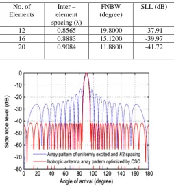
OPTIMAL INTER-ELEMENT SPACING, FNBW AND SLL FOR LINEAR ARRAY ELEMENTS [7]
No. of Elements
Inter – element spacing (λ)
FNBW (degree)
SLL (dB)
12 0.8565 19.8000 -37.91 16 0.8883 15.1200 -39.97 20 0.9084 11.8800 -41.72
Fig.3 output radiation pattern for 20-element linear array using cat swarm optimization [7]
Analyzing the data from TABLE 3, it is resulted that besides the minimization of SLL, first null beam width (FNBW) is restricted upon synthesis. By utilizing the CSO on nonuniform linear array synthesis, max. Reduction in SLL -41.72dB for 20-elements is obtained with the constraint of FNBW. A comparative output radiation pattern for uniform array and optimized linear array with cat swarm optimization is illustrated in Fig. it is observed that synthesized optimal pattern get by CSO provides max SLL reduction in desired direction than a uniform λ/2 spacing array pattern [7].
D. Ant lion algorithm
The aim of this paper is to introduce the Ant Lion Optimization (ALO) algorithm to the electromagnetic and antenna community. ALO is a new nature-inspired algorithm using the hunting behavior of ant lion and is used to solve constrained as well as unconstrained optimization problems. In this work, Ant loin algorithm has been depicted for antenna current as well as antenna inter-element position optimization for pattern synthesis of linear antenna arrays [7]. The main goal of ALO to perform linear array beam steering by optimizing the antenna phases is also presented. The array factor is employed to excess the use of ALO for linear array optimization so as to obtain its characteristics such as low side lobe level (SLL) along with null placement in the important directions and HPBW [8].
Fig.4 (a) Cone-shaped pits/traps and (b) foraging behavior of ant lions [8].
Fig.4 shows a process that how an ant lion digs a cone shaped pit in sand with small movement along a circular path and throwing out sands with its massive jaw. Fig.4 (a) illustrates several cone-shaped pits of various sizes. Ant lion is a sit-and-wait predator; through, after digging the trap, the ant lion collapse underneath the bottom of the cone and waits for insects to be trapped in the pit as illustrated in Fig.4 (b).
In this work consider the two design examples A and B by taking 2N = 10 and 16 respectively. In case of example A, array antenna side lobes are addressed at angles 𝜃𝜃 =
[0𝑐𝑐, 760] and 𝜃𝜃 = [104𝑐𝑐, 180𝑐𝑐]. The array synthesis outcomes evaluated by Ant lion optimization (ALO) are depends on its control parameters such as inter-element spacing and phase excitations. Using ALO, the obtained peak SLL is improved by 1.46 dB as compared to PSO as illustrated in TABLE 4.
TABLE 4
COMPARISON RESULT FOR REDUCED SLL BY PSO AND ALO BY NO OF ELEMENTS [8]
No. of Elements
Uniform array
PSO proposed
10 -12.97 -24.62 -26.08 16 -13.15 -30.63 -30.83
[image:4.595.32.287.340.613.2]optimized element positions are compared for 10-element array antenna design using PSO and ant line algorithms [8].
TABLE 5 OPTIMIZED POSITIONS OF 10- ELEMENT ARRAY [8]
Method optimized element positions
PSO 0.1516 λ 0.4115 λ Proposed 0.1259 λ 0.3751 λ
The results obtained from antenna array study indicates that ALO yields better performance compared to the uniform array and the array synthesis using other evolutionary algorithms [8].
E. Gravitational search algorithm
A new evolutionary optimization approach gravitational search algorithm (GSA) is proposed in this paper, which is based on the Newtonian law of gravity and mass interaction. The present work demonstrates the use of GSA optimization for the synthesis of uniform linear antenna arrays with low side lobe level around the main beam. The goal of this study is to obtain the desired radiation pattern of planer array by targeting minimum SLL and null controlling with position only synthesis [9]. The programming of linear antenna array is computed in MATLAB software. For side lobe suppression, the fitness function utilized for low SLL is calculated as:
𝐴𝐴= ∑ 1
∆𝜑𝜑𝑚𝑚∫ |𝐴𝐴𝐴𝐴(𝜑𝜑)| 2𝑑𝑑𝜑𝜑 𝜑𝜑𝑛𝑛𝑚𝑚
𝜑𝜑𝑙𝑙𝑚𝑚 𝑀𝑀
𝑚𝑚 (11)
Where,[𝜑𝜑𝑙𝑙𝑚𝑚,𝜑𝜑𝑛𝑛𝑚𝑚] are the regions of low SLL, M is the no. of reasons and ∆𝜑𝜑 = 𝜑𝜑𝑛𝑛𝑚𝑚 - 𝜑𝜑𝑙𝑙𝑚𝑚. Therefore, GSA is utilized to minimize this fitness function. The first example considers the 10-element linear array optimization, where excitation phase is kept fixed.
The obtained results for SLL and inter- element positions normalized with λ/2, are compared with particle swarm optimization for better performance. TABLE displays the reduction of SLL for PSO and GSA optimization [9].
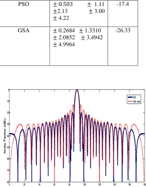
The second example is based on the synthesis of 28 – element array antennas by targeting SLL and null control at 990 is illustrated in Fig. The population size is 40 and no. of iterations is 500, are fixed for GSA optimization [9]. The fitness function or cost function proposed in this paper for null control in array pattern is calculated as:
𝐴𝐴𝑚𝑚𝑐𝑐𝑛𝑛𝑖𝑖𝑐𝑐𝑐𝑐= ∑ ∆𝜃𝜃1
𝑚𝑚∫ |𝐴𝐴𝐴𝐴(𝜃𝜃)|
2𝑑𝑑𝜃𝜃+ ∑ |𝐴𝐴𝐴𝐴(𝜃𝜃)|2 𝑘𝑘
𝜃𝜃𝑛𝑛𝑚𝑚 𝜃𝜃𝑙𝑙𝑚𝑚
𝑚𝑚 (12)
The results describes that the max. Null depth obtained by GSA is -84.68dB and side lobe level reduction as -30 dB which shows superior performance of GSA then PSO.
In this paper, linear array synthesis is accomplished by isotropic elements, but in future GSA may be effectively employed for the optimization of non-isotropic element linear or planner arrays [9].
[image:5.595.314.561.145.462.2]
TABLE 6 comparative results for 10-element linear array
Algorithm Element positions SLL
Conventional array ± 0.50 ± 1.50
±2.50
± 3.50 ± 4.50
-12.97
PSO ± 0.503 ± 1.11
±2.13 ± 3.00
± 4.22
-17.4
GSA ± 0.2684 ± 1.3310
± 2.0852 ± 3.4942
± 4.9964
-26.33
Fig.5 28-element linear array pattern using GSA and conventional array [9]
OVERALL ANALYSIS OF SLL REDUCTION ALGORITHMS
TABLE 7
COMPARISON OF ARRAY PATTERN SYNTHESIS ALGORITHMS FOR SLL, FNBW, AND NULL DEPTH
Algorith m
Numbe r of elemen
ts
Side lobe level(d
B)
FNBW(degr ee)
Max. Null depth(d
B) MIWO 12
16 20
-26.52 -25.96 -17.25
44.0 33.87 23.38
-64.83 -59.15 -55.86
GA 12
16 20
-20.53 -15.05 -13.27
19.88 14.40 11.62
-55.83 -45.35 -56.62 CSO 12
16 20
-37.91 -39.97 -41.72
19.800 15.120 11.880
−
ALO 10 16
-26.08 -30.83
_ -79.83
GSA 10 28 32
-26.33 -26.36 -20.16
− -77.30 -84.64
CONCLUSIONSANDFUTURESCOPE
After reading some literature about antenna array it concludes that, an antenna array application with high directivity and low side lobe level is an important technology that can raise the reliability and validity of a communication system [14]. The design analysis of antenna array pattern has been extensively studied in the last few decades. Nowadays researchers give careful consideration on the techniques to control nulls directions in non-isotropic array radiation pattern with the fixation of half power beam width (HPBW). Research is going on to further improve the side lobe level suppression and also the performance of antenna array system. The future scope of antenna array synthesis is in large communication systems and different real world physical applications like in future 5G generation Samsung smart phones [15].
REFERENCES
[1] C.A. Balanis: Antenna Theory: Analysis and Design, John
Wiley and Sons, Hoboken, NJ, USA, 2005.
[2] Adam Raniszewski, "Radiation pattern synthesis for RADAR application using Genetic Algorithm", 21st International Conference on Microwave Radar and Wireless Communications
[3] Shi-Wei Qu, Shiwen Yang, “Novel Parasitic Micro Strip
Array for Low- Cost Active Phased Array Applications,” IEEE Transactions on Antenna and Propagation, Vol. 62, April 2014.
, 2016.
[4] Ashwin Kothari. "Optimal pattern synthesis of linear
antenna array using grey wolf optimization algorithm."
[5] El-Hadi and Christophe Dumond et.al. "A novel Modified
Invasive Weeds Optimization for linear array antennas nulls control."
International Journal of Antennas and Propagation (2016).
[6] D.D. Dajab and K. Ahmad. "Synthesis of a Linear Antenna
Array for Maximum Side-lobe Level Reduction."
2015 4th International Conference on Electrical Engineering (ICEE). IEEE, 2015.
International Journal of Computer Applications
[7] Debalina Ghosh et al. "Linear Antenna Array synthesis using
cat swarm optimization", AEU-International Journal of Electronics and Communications 68, 2014.
85. (2014).
[8] Saxena, Prerna, and Ashwin Kothari. "Ant Lion
Optimization algorithm to control side lobe level and null depths in linear antenna arrays." AEU-International Journal of Electronics and Communications
[9] Maryam Hesari and Ataallah Ebrahimzadeh."Introducing Deeper Nulls and Reduction of Side-Lobe Level in Linear and Non-Uniform Planar Antenna Arrays Using Gravitational Search Algorithm," Progress In Electromagnetics Research B, Vol. 73, 2017.
70, no. 9 (2016): 1339-1349.
[10] Mahmoud, Korany Ragab. "Synthesis of unequally-spaced
linear array using modified central force optimization algorithm." IET Microwaves, Antennas & Propagation
[11] Li, Xiangtao, and Minghao Yin. "Linear antenna array
synthesis using orthogonal artificial bee colony algorithm."
10, no. 10 (2016).
Journal of Computational and Theoretical Nanoscience
[12] Florine Enache and Andrei Enache, "Multi-Criteria Optimization of Non-Uniform Linear Antenna Array using Genetic Algorithms," IEEE 2016.
10, (2013).
[13] Lei Chen and Xiao-Wei Shi, "An Iteration Method of
Sidelobe Suppressing of Unequally Spaced Array," 3rd Asia-Pacific Conference on Antennas and Propagation, IEEE 2014.
[14] Shuang Liang and Geng Sun, "Sidelobe-level suppression for
linear and circular antenna arrays via the cuckoo search– chicken swarm optimization algorithm," IET Microwaves, Antennas & Propagation 2016.
[15] V.S Gangwar and S P Singh, "Side Lobe Level Suppression
in Randomly Spaced Linear Array Using Genetic
![TABLE 2 SLL, Null Depth and FNBW for non-uniform linear array using RGA [6]](https://thumb-us.123doks.com/thumbv2/123dok_us/687294.1076130/3.595.307.568.436.525/table-null-depth-fnbw-uniform-linear-array-using.webp)