6 | P a g e
POWER QUALITY IMPROVEMENT IN MICROGRID
USING ADVANCED ACTIVE POWER CONDITIONER
K. Rajesh Kumar
1, K.Narasimha Swamy
21
PG Scholar,
2Assistant Professor, DVR & Dr.HS MIC College of Technology
ABSTRACT
Wind energy conversion systems are now occupying important space in the research of renewable energy
sources with Microgrid. The main challenge in wind power generation is power quality problem and their
connection with the distribution network in Microgrid. The main factor behind poor power quality is the impact
of harmonics in current and voltage in power network. In Microgrid the converter and rectifier are using to
convert AC-DC-AC to interconnection of wind power and load to Microgrid. The converter and rectifier are
producing the significant harmonics. In this paper presents a three-phase Active Power Conditioner to improve
power quality in Microgrids based on renewable energy. A Microgrid is a weak electrical grid which can be
easily subject to disturbances. The Active Power Conditioner (APC) presented in this paper acts as an interface
between renewable energy sources and the AC bus of a Microgrid and uses an improved control strategy, which
makes possible to inject energy in the Microgrid, compensate the current harmonics and correct the power
factor.Simulation results show the validity of the innovative control strategy
Keywords: Active Power Conditioner, Microgrids, Renewable Energy, Current control, Harmonics
I. INTRODUCTION
Due to an increase in power demand and fossil fuel shortage, renewable energy supplies have become an essential to full fill the energy demand in the age of technology. The wind power plants have huge contribution to the production of renewable energy. Although wind power plant has a major contribution in renewable energy, the power generated by wind turbines overtime is uneven due to the unpredictable nature of their primary sources of power which increases the problems inherent to the integration of a great number of wind turbines into Microgrid. The contribution of wind power plants faces certain challenge like voltage and frequency regulation [1].
In an electrical power system Microgrid is the name given to a group of electric loads and power generation from different sources like wind, solar etc. operation as a controllable system that inject electric power to its local area and regional grid [2][3]. The Microgrid play an important role to enhance local reliability, increase efficiency, support local voltage, voltage sag correction, on provide uninterruptible power supply function [4][5].
7 | P a g e
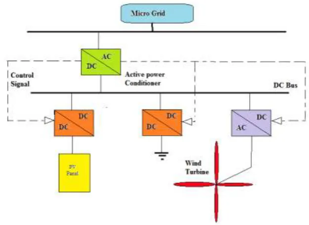
Figure 1. APC for Microgrid applications
This paper presents an APC used to improve the power quality in a Microgrid. The attention will be mainly focused on the innovative control strategy, which allows injecting energy in the Microgrid, compensating the current harmonics, correcting the power factor and balancing the supply voltage at the PCC. The validity of the control strategy has been proved through many simulation tests using SimPowerSystems from MATLAB/SIMULINK.
II. MICROGRID STRUCTURE
The Microgrid structure assumes an aggregation of loads and micro sources operating as a single system providing both power and heat. The majority of the micro sources must be power electronic based to provide the required flexibility to insure controlled operation as a single aggregated system. This control flexibility allows the Microgrid to present itself to the bulk power system as a single controlled unit, have plug-and-play simplicity for each micro source, and meet the customers’ local needs. These needs include increased local reliability and security.
Key issues that are part of the Microgrid structure include the interface, control and protection requirements for each micro source as well as Microgrid voltage control, power flow control, load sharing during islanding, protection, stability, and over all operation. The ability of the Microgrid to operate connected to the grid as well as smooth transition to and from the island mode is another important function.
8 | P a g e concept. The feeders are usually 480 volts or smaller. Each feeder has several circuit breakers and power and voltage flow controllers. The power and voltage controller near each micro source provides the control signals to the source, which regulates feeder power flow and bus voltage at levels prescribed by the Energy Manager. As downstream loads change, the local micro source’s power is increased or decreased to hold the total power flow at the dispatched level.
Fig.2 Microgrid Architecture
III. ACTIVE POWER CONDITIONER TOPOLOGY
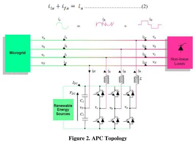
The most utilized topology, to manage four currents, is four-leg converters [9]. This topology has proved better controllability [10] than the classical three-leg four-wire converter but the latter is preferred because of its lower number of power semiconductor devices. In this paper, it is shown that using an adequate control strategy, even with a simple three-leg four-wire system, it is possible to mitigate disturbances like voltage unbalance, THD and others. The topology of the investigated APC and its interconnection with the microgrid is presented in Fig. 2. It consists of a three-leg four-wire voltage source inverter. In this type of applications, the VSI operates as a current controlled voltage source. In order to provide the neutral point, two capacitors are used to split the DC-link voltage and tie the neutral point to the mid-point of the two capacitors. This topology allows the current to flow in both directions through the switches and the capacitors, causing voltage deviation between the DC capacitors.
………(1)
Where:
are phase APC currents and ifN is the APC neutral current.
9 | P a g e For the investigated topology presented in Fig. 3, the current at (PCC) is:
……….(2)
Figure 2. APC Topology
arethe Microgrid side current, the load current, and the APC current respectively. The x index points
the a, b and c current phases. The instantaneous load current is:
………..(3)
where:
- the fundamental active current component;
- the addition of current harmonics;
- the reactive current component.
The three-phase APC current is given by:
………..(4)
- the fundamental conditioner current component;
- the deforming component of the current.
As shown in Fig. 3 the current drawn from the grid has to be sinusoidal and moreover, in phase with the voltage at PCC. Consequently, the control strategy for the APC has to be designed in order to ensure a sinusoidal wave for the grid current (ix).
………(5)
10 | P a g e
IV. CONTROL OF THE APC
4.1 Control Strategy
There are many ways to design a control algorithm for an APC [11]. Generally, the controller design is made considering that the grid voltage at the PCC is balanced. In a Microgrid, the supply voltage itself can be distorted and/or unbalanced. Consequently, the controller of an APC used to improve the power quality in the Microgrid has to be designed according to the weakness of this kind of grid.
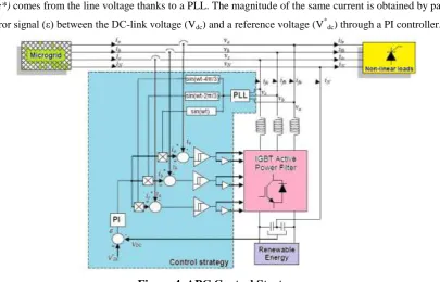
The proposed control algorithm is a compensation method that makes the APC compensate the current of a non-linear load by forcing the Microgrid side current to become sinusoidal and balanced (Fig. 3). The controller requires the three-phase grid current (ia, ib, ic), the three-phase voltage at the Pcc (va, vb, vc) and the DC-link voltage (VDC). As shown in Fig. 4, the sinusoidal waveform and the phase of the grid current reference (ia*,
ib*, ic*) comes from the line voltage thanks to a PLL. The magnitude of the same current is obtained by passing
the error signal (ε) between the DC-link voltage (Vdc) and a reference voltage (V *
dc) through a PI controller.
Figure 4. APC Control Strategy
Using this magnitude and phase displacement of 120° and 240° respectively, the reference three-phase grid
currents can be expressed as:
4.2 Switching Control
11 | P a g e Compared with linear controllers, the non-linear ones based on hysteresis strategies allow faster dynamic response and better robustness with respect to the variation of the non-linear load. A drawback of the hysteresis strategies is the switching frequency which is not constant and can generate a large side harmonics band around the switching frequency.
To avoid this drawback, the switching frequency can be fixed using different solutions like variable hysteresis bandwidth or modulated hysteresis. But this is not the object of this paper.
V. SIMULATION RESULTS
The simulation was performed on the MATLAB/ SIMULINK package. Simulink is a software package for modeling, simulating and analyzing dynamic systems. It supports linear and nonlinear systems, modeled in continuous time, sampled time, or a hybrid of the two. Systems can also be multirate, i.e., having different parts that are sampled or updated at different rates. In this the Simulink models of the shunt active filter with hysteresis current controller are given along with simulation results.
An extensive simulation study is carried out using MATLAB/Simulink in order to verify the proposed control strategy. To achieve balanced sinusoidal grid currents at unity power factor, the 3-leg grid interfacing inverter is actively controlled using renewable energy source. The simulation results are grouped and presented according to the following power quality indicators: THD(Total Harmonic Distortion),power factor and unbalanced load.
5.1 Harmonics Compensation
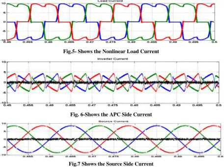
During this case study, the APC is investigated using a three-phase diode bridge rectifier with a 60Ω resistor in series with a 0.1mH inductor at the DC side.
Fig.5- Shows the Nonlinear Load Current
Fig. 6-Shows the APC Side Current
12 | P a g e Fig.5,6,7 shows the currents at the PCC. As can be seen, most of the current required by the load is injected by the APC and the balance comes from the microgrid, The current absorbed by the rectifier is not sinusoidal
5.2 Power Factor Correction
The second case study shows the effectiveness of the APC to compensate the power factor. The power faction can be controlled with the capacitor banks, but this is the manual operation. In distorted conditions the results are power and also the capacitor life is shorter. So maintenance cost also high. For this case study, the load is composed by a three-phase inductor in series with a three-phase resistor and requires about 3KW active power and 4kVAR reactive power.
Fig.8- Before Compensation
Fig.9- After Compensation
Fig.8 illustrates the load current, the microgrid side current and the supply voltage respectively at the PCC of phase-a. As shown in fig.9 the measured power factor between the load current and the supply voltage is 0.58. Thanks to the proposed control strategy, the APC is able to impose a unity power factor between the microgrid side currents and the supply voltage. The phase of the microgrid side currents is inverted relatively to the phase of supply voltages at the PCC because the power injected by the APC exceeds the power required by the load. Consequently, the surplus renewable energy is injected into the microgrid.
VI. CONCLUSIONS
In this paper, an APC used to improve power quality in microgrids based on renewable energy has been presented. The APC is controlled using an innovative control strategy allowing the line current at the point of common coupling to be balanced and sinusoidal even when the load is unbalanced.
This approach presents the following advantages:
The control system is simpler, because only three sinusoidal waveforms have to be generated for the
reference currents.
These sinusoidal waveforms to control the current are generated in phase with the main supply, allowing
unity power-factor operation.
The control of the three-phase line current enables the three-phase voltage balance at the PCC, allowing
13 | P a g e REFERENCES
[1] Majid mumtaz, “ Harmonic Domain modeling of wind based microgrid”, university of Glasgow, 2012. [2] Dvorsky E, Hejtmankova P. Skorpil J. “ Control of micro-grids with renewable power sources”, IEEE,
PES transmission and distribution conference and exposition, PP 1-4.2008.
[3] Lasseter R.H. micrgrids In: IEEE power eng SOC transindistrib conf. pp 305-308,2002
[4]. Marnay c, Venkataramana G, microgrids in the evolving electrical generation and delivery infrastructure. In:IEEE power eng SOC gen meet: pp 18-22, 2006.
[5] Pecas lopes J. A, moreira C.L. ,Madureira A.G., defining control strategies for microgrids islanded operation, IEEE trans power system. Pp 916-924, 2006
[6] M. Abdusalama, P. Poureb, S. Karimia and S. Saadatea “New digital reference current generation for shunt active power filter under distorted voltage conditions,” Electric Power Systems Research, vol. 79, pp 759- 765, May 2009.
[7] M.Montero, E.R. Cadaval, F. Gonzalez, “Comparison of control strategies for shunt active power filters in three-phase four-wire systems”, IEEE Transactions on Power Electronics, vol. 22, pp. 229– 236, January 2007.
[8] B. Singh, K. Al-Haddad, A. Chandra “A Review of Active Filters for Power Quality Improvement” IEEE Transactions on Power Electronics, vol. 46, pp. 960-971, October 1999.
[9] J. Chen, F. Liu , S. Mei, “Nonlinear disturbance attenuation control for four-leg active power filter based on voltage source inverter,” Journal of Control Theory and Applications vol. 3 pp. 261–266, August 2006.
[10] M. Ucara and E. Ozdemir “Control of a 3-phase 4-leg active power filter under non-ideal mains voltage condition,” Electric Power Systems Research, vol. 78, pp. 58-73, January 2008.