ISSN (Online) : 2319 - 8753 ISSN (Print) : 2347 - 6710
I
nternationalJ
ournal ofI
nnovativeR
esearch inS
cience,E
ngineering andT
echnology Volume 3, Special Issue 3, March 20142014 International Conference on Innovations in Engineering and Technology (ICIET’14) On 21st & 22nd March Organized by
K.L.N. College of Engineering, Madurai, Tamil Nadu, India
ABSTRACT— As the conventional sources of power generation are reducing every day there is a strong need for a sustainable and clean source of power which could supply the need. Wind energy conversion systems play a very vital role in production of clean and sustainable energy. In this paper, a DFIG based wind energy system employing DFIG as the power generator is modeled. To improve the transient and steady state performance and the power factor of generation, a stator flux oriented vector control scheme is used in this work. The vector control structure employs conventional PI controllers for the decoupled control of the stator side active and reactive power. This paper emphasizes only on the control of the rotor side bidirectional converter. The whole system is modeled and simulated using Matlab/Simulink and the results are analyzed.
KEYWORDS— Doubly-fed induction generator, Rotor-side inverter, stator flux oriented vector control, P- I controller, SPWM inverter.
I. INTRODUCTION
With the development of power electronic equipments variable speed wind power generation has become simpler and more efficient. In variable speed wind energy systems efficient power capture from wind has always been a subject of great concern. To capture wind power efficiently the speed of the wind turbine and generator has to be continuously changed so as to maintain the power coefficient at its maximum value. Doubly fed induction generators are efficient and robust machines and are widely used as modern wind power generators. DFIG based wind turbines have several advantages like cost
effectiveness, easy pitch angle control, reduction in torque and power pulsation and most importantly improved power quality. The greatest benefits of using DFIGs as power generators are that the control of DFIG is done from the rotor side. So the rotor converters have to deal with less power and hence are less power rating and size. Again as the ratings are less the switching losses are also less and the control structure is more reliable and efficient [1, 2, 3, 5, 7]. Induction generators have an inherent coupling between active and reactive power which makes the response active and reactive power sluggish. But, this disadvantage can be overcome by the use of advanced control strategies such as vector control[1-5,7,10-14], direct torque control[12] and direct power control[8, 9] strategies. For the control of DFIGs most often stator flux oriented vector control [2, 3, 5, 7] strategy is used. This strategy provides independent control of active and reactive power of the DFIG by coupling them. In the above mentioned scheme along with conventional PI controllers many type of advanced controllers are implemented such as sliding mode controller[15], fuzzy logic controllers[7] etc, for the performance improvement of the scheme.
In this paper a DFIG based WECS is considered. The DFIG is controlled from the rotor side by a stator flux oriented vector controlled scheme employing PI controllers. Only the control of rotor side bi-directional converter is emphasized in this paper. The RSC is a PWM converter for which the switching pulses are generated from a sinusoidal PWM strategy. The whole scheme is simulated with MATLAB/SIMULINK environment and the results are analyzed.
A Stator Flux Oriented Vector Control Scheme For
Decoupled Control Of DFIG For Wind Energy
Applications
Swagat Pati
#1, Manas Patnaik
#2, Tapan Kumar Pattanaik
#3#1Department of Electrical Engineering, Siksha „O‟ Anusandhan University,Bhubaneswar, Odisha, India.
#2Department of Electrical Engineering, Siksha „O‟ Anusandhan University, Bhubaneswar, Odisha, India
#3
II. MODELINGOFDOUBLY-FEDINDUCTION
GENERATOR
The dynamic model of DFIG is derived after the three phase quantities were transformed to two phase direct quadrature axes quantities. The concept of power invariance was used to determine the equivalence between the three phase and two phase machine models. The stator and rotor equations of voltage in synchronously rotating reference frame [4] are as follows
Where, Vds = VdI, Vqs = VqI, VdI and VqI are the direct and quadrature axis voltages respectively.
The stator flux linkages are given as:
6
5
qr m qs s qs
dr m ds s ds
I
L
I
L
I
L
I
L
The rotor flux linkages are given as:
8
7
qs m qr r qr
ds m dr r dr
I
L
I
L
I
L
I
L
The torque balance equation for generator is given below.
Fig.1 Block diagram of vector control scheme for generator control
Where,
Te= electromagnetic torque, J= Inertia of rotor,
m
= mechanical speed.The electromagnetic torque generated by DFIG is given as:
The active and reactive powers of the DFIG are given as in equations (11) and (12).
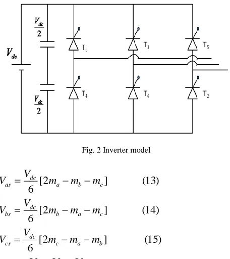
III. INVERTER MODEL
The control structure of a DFIG consists of two back to back bidirectional PWM inverters connected by a DC link. The converters are namely RSC rotor side converter and GSC grid side converters. The rotor side converter is used for the vector control of the DFIG for performance improvement and stator power flow control, and the GSC is used for keeping the DC link voltage constant and power factor improvement of the rotor side. In this work the RSC control is done and the results are analyzed assuming DC link voltage to be constant.
A simplified pwm inverter model diagram [6] is shown in the Fig. 2
4
)
(
)
(
3
)
(
)
(
2
)
(
1
)
(
dr r e qr qr
r qr
qr r e dr dr
r dr
ds e qs qs
s qs
qs e ds s
d s ds
dt
d
I
R
V
dt
d
I
R
V
dt
d
I
R
V
dt
d
I
R
V
-
(10)
2
2
3
qr ds dr qs m
e
L
I
I
I
I
P
T
(11)
qs qs ds ds
I
V
I
V
P
(12)
qs ds ds qs
I
V
I
V
Q
(9)
m m
turbine
e
B
dt
d
J
T
r s s
2 m o
L
L
1
σ
L
L
=
L
2 m
L
-=
and
Fig. 2 Inverter model
)
15
(
]
2
[
6
)
14
(
]
2
[
6
)
13
(
]
2
[
6
b a c dc cs
c a b dc bs
c b a dc as
m
m
m
V
V
m
m
m
V
V
m
m
m
V
V
Where:
V
as,V
bs,V
csare the phase voltages,T1 to T6 areswitching states of the switches which can be either 1 or 0 depending on whether they are on or off respectively.
dc
V
: DC supply voltage.a
m
: 2T1-1,m
b: 2T3-1,m
c: 2T5-1.IV. PICONTROLLER DESIGN
The vector control strategy employs three conventional PI controllers for the fats and precise control of DFIG. PI controllers are simple but have some drawbacks. Normally the controllers should be simple, fast, accurate and robust so that they control the system quickly with the change in the parameters. The mathematical equations of PI controller are as follows.
(
16
)
k
e
k
e
dt
u
p i)
17
(
r r
e
Where,
r
: Reference electrical speed,r
: Actual electrical speed,p
k
: Proportional gain,i
k
is the Integral gain.The trial and error method is used to tune the PI controller in order to get the near optimal output.
V. CONTROL STRUCTURE
The DFIG is controlled by a vector controlled scheme which provides a decoupled control of active and reactive power. The vector control scheme is implemented on the rotor side of the DFIG, the stator being connected directly to the supply. Here the reactive power is controlled by the direct axis loop and the active power is controlled by the quadrature axis loop. The equations related to the scheme are as follows.
Where, „ims‟= stator side magnetizing current
The direct and quadrature axis reference control voltages are given below.
The direct and quadrature axis reference control voltages are then converted to three phase quantities and are compared with a triangular carrier and the switching pulses are generated. The modulation index is set to 0.8 and switching frequency to 10 kHz. Then the switching pulses are given to the bidirectional inverter which supplies to the rotor of the DIFG.
VI. SIMULATION AND RESULT ANALYSIS
The DFIG control structure was modeled and simulated in Matlab Simulink. The PWM scheme is sinusoidal PWM. The simulation results are obtained as follows.
Step change in reference speed
Step change in reactive power
Step change in torque
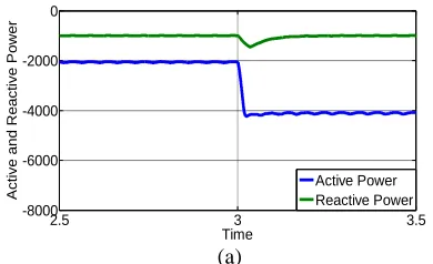
A. Change in speed:
The speed is changed from 1400 rpm to 1700 rpm at 3 seconds keeping torque and reactive power constant. The values of torque and reactive power are 20 Nm and -1000Var respectively.
The figure (e) shows the speed graph in which the speed switches to 1700 rpm from 1400 rpm at 3 seconds. As the speed increases the reactive power remains the same but the active power increases little after the step change as shown in the figure (a). But, there is a decrease in the active and reactive power on the rotor side. The reactive power becomes negative after the step change as the new speed is super-synchronous as shown in Fig. (c). Power factor is around 0.9 on the stator side as shown in Fig. (b). But, the power factor on the stator side after the step change falls becomes nearly zero as shown in Fig. (d). It is because of the reason the active power falls to zero. The torque as shown by the figure (f) is zero throughout except in the transient stage.
L
rI
dr
(19)
sl o ms
qr r qr r
qr
L
I
dt
di
L
I
R
V
(20)
i
L
-
sl r qr*
dr dr
U
V
(21)
i
L
r dr sl *ms o dr
qr
U
L
i
V
(18)
I
L
-
sl
r qr
dt
di
L
I
R
2.5 3 3.5 -1
-0.5 0 0.5
Time
A
ct
ive
a
nd
Re
act
ive
P
owe
r
Active Power Reactive Power
0 1 2 3 4 5 6 7
0 0.5 1 1.5
Time
P
o
we
r
F
a
ct
o
r
(b)
2.5 3 3.5
-2000 -1000 0 1000 2000 3000 4000
Time
A
ct
ive
a
n
d
Re
a
ct
ive
P
o
we
r
Active Power Reactive Power
(c)
2.5 3 3.5
-0.5 0 0.5 1 1.5
Time
P
o
we
r
F
a
ct
o
r
(d)
2.5 3 3.5
1000 1200 1400 1600 1800 2000
Time
S
pe
ed
(e)
2.5 3 3.5
-1000 -500 0 500 1000
Time
T
o
rq
u
e
(f)
Fig. 3: Responses for change in Speed with Time. (a) Active and Reactive Power of stator side. (b) Power factor of stator side. (c) Active
Speed. (f) Torque.
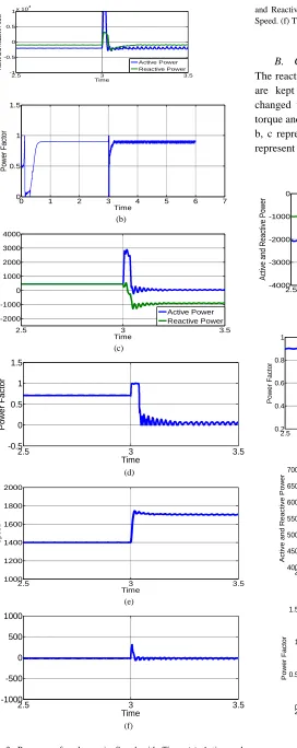
B. Change in Reactive Power:
The reactive is varied in steps while the torque and speed are kept constant. At 3 seconds the reactive power changed from -1000VAR to -3000VAR. The values of torque and speed are -20 Nm and 1400 rpm. The figures a, b, c represents for the stator side and the figures d, e, f represent for the stator. The outputs are as follows.
2.5 3 3.5
-4000 -3000 -2000 -1000 0
Time
A
ct
ive
a
nd
Re
act
ive
P
owe
r
Active Power Reactive Power
(a)
2.5 3 3.5
0.2 0.4 0.6 0.8 1
Time
P
o
we
r
F
a
ct
o
r
(b)
2.5 3 3.5 4 4.5 5 5.5 6
400 450 500 550 600 650 700
Time
A
ct
ive
a
n
d
Re
a
ct
ive
P
o
we
r
Active Power Reactive Power
(c)
2.5 3 3.5
0 0.5 1 1.5
Time
P
o
we
r
F
a
ct
o
r
2 2.5 3 3.5 4 1200
1300 1400 1500 1600
Time
S
p
e
e
d
(e)
2.5 3 3.5
-80 -60 -40 -20 0 20 40 60
Time
T
o
rq
u
e
(f)
Fig. 4: Responses for change in Reactive Power with time.(a)
Active and Reactive Power of stator side. (b) Power factor of stator side. (c) Active and Reactive Power of rotor side. (d) Power Factor of rotor side. (e) Speed. (f) Torque.
The figure (a) shows the change in reactive power from -1000 VAR to -3000 VAR at 3 seconds. There is no change in the power. It is -2000 W before and after the step change. The power factor on the stator side drops from 0.9 to 0.57 after the step change as shown in the figure (b). The active power increases from 450 W to 655 W and reactive power increases from 450 VAR to 605 VAR as can be seen in the figure (c). The figure (d) shows how the power factor on rotor side increases from 0.65 to 0.8. The figure (e) shows that speed is constant i.e. 1400 rpm throughout, except in the transient period. Torque is constant i.e. -20 N-m as shown in the figure (f).
C. Change in Torque:
The torque is changed from -20 Nm to -40 Nm at 3 seconds. The speed and reactive power are kept constant. The reference values for speed and reactive power are 1400 rpm and -1000VAR respectively.
2.5 3 3.5
-8000 -6000 -4000 -2000 0
Time
A
ct
ive
a
n
d
Re
a
ct
ive
P
o
we
r
Active Power Reactive Power
(a)
2.5 3 3.5
0.4 0.6 0.8 1 1.2 1.4
Time
P
o
we
r
F
a
ct
o
r
(b)
2.5 3 3.5
100 200 300 400 500 600 700 800
Time
A
ct
ive
a
n
d
Re
a
ct
ive
P
o
we
r
Active Power Reactive Power
(c)
2.5 3 3.5
0 0.5 1 1.5
Time
P
o
we
r
F
a
ct
o
r
(d)
2.5 3 3.5
1350 1400 1450
Time
S
p
e
e
d
(e)
2.5 3 3.5
-100 -50 0 50
Time
T
or
qu
e
(f)
Fig. 5: Responses for change in Torque. (a) Active and Reactive
Power of stator side. (b) Power factor of stator side. (c) Active and Reactive Power of rotor side. (d) Power Factor of rotor side. (e) Speed. (f) Torque.
power remains unaffected .i.e. -1000VAR on the stator side as given in the figure (a). The active power increases on the rotor side from 450W to 700W whereas the reactive power increases from 450VAR to 465VAR as can be seen in figure (c). The power factor is seen to increase on both rotor and stator side. The rotor side power factor increases from 0.7 to 0.8 as shown in the figure (d) and the power factor increases from 0.9 to 0.95 on the stator side as shown in the figure (b).The speed before and after the step change are same as that of reference speed .i.e. 1400 rpm as can be seen in the figure (e).
VII. CONCLUSION
The rotor side control of DFIG using PI controller with SPWM inverter was successfully modeled and discussed in the paper. The outputs related to the model were analyzed. The transient, steady state performance and power factor were found to be improved. It is also evident from the results that the power can be fed to the grid at any desired power factor. High performance control of power can be achieved by the proposed scheme as the vector control scheme facilitates the decoupled control of active and reactive power.
APPENDIX
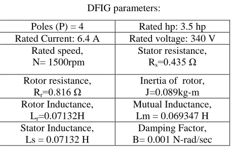
DFIG parameters:
REFERENCES
[1] Bin Wo,Y.Lang, N.Zargari, Samir Kouro, “Power conversion and control of wind energy system” , John Wiley and sons Publication, IEEE Press, 2011.
[2] A.Tapia, G.Tapia, J.Ostolaza, “Modeling and Control of a Wind Turbine Driven Doubly Fed Induction Generator”, IEEE Trans on Energy Conv.Vol-18,No-2,June-2003.
[3] S. N. Bhadra, D. Kastha, and S .Banerjee, Wind Electrical Systems, Oxford University Press, New Delhi, 2005.
[4] P.C Krause, O.Wasynczuk, S.D.Sudhoff, “Analysis of Electrical Machinery”, John Wiley and sons Publication, IEEE Press. [5] R. Cardenas, and R. Pena, “Sensorless vector control of induction
machines for variable speed wind energy applications,” IEEE Trans. Egy.Conv., vol. 19, no. 1, pp. 196-205, Mar. 2004. [6] Peter Vas , “ Sensor-less vector control and Direct Torque control”,
Oxford University Press, New Delhi .
[7] B.K Bose “modern power electronics and ac drives” Prentice-Hall Publication,Englewood Cliffs,New Jersey,1986.
switching frequency and improved transient performance”, IEEE transactions on energy conversion , Vol.22, No.1 March 2007. [9] Gonzalo Abad, Miguel Angel Rodriguez, Grezegorz Iwanski,
Javier Poza,” Direct power control of doubly fed induction generator based wind turbines under unbalanced grid voltage,” IEEE transactions on power electronics, Vol.25, No.2, Februrary 2010.
[10] Andrew Miller, Edward Mujadi, Donald S.Zinger, “A variable speed wind turbine power control”, IEEE transaction on energy conversion, Vol.12, No.2, June 1997.
[11] Hee-Sang Ko, Gi-Gab Yoon, Nam-Ho Kyung, Won-Pyo Hong, “Modelling and control of DFIG based variable speed wind turbine”, electric power system research, Elseviers.
[12] Jihen Arbi, Manel Jebali- Ben Ghorbal, IIhem Slama-Belkhodja, Lotfi Charaabi,” Direct virtual torque control for doubly fed induction generation grid connection”, IEEE transactions on industrial electronics, Vol.56, No.10, October 2009.
[13] Andreas Petersson, ”Analysis, modelling and control of doubly fed induction generators for wind turbines”,dissertation for the degree of doctor of philosophy, department of energy and environment chalmers university of technology, goteborg, sweden2005. [14] Etienne Tremblay, Sergio Atayde, Ambrish Chandra,
“Comparative study of control strategie for the doubly fed induction generation in wind energy conversion systems: A DSP-based implementation approach”, IEEE transactions on sustainable energy, Vol.2, No.3, July 2011.
[15] D.Chwa , Kyo-Beum “ Variable Structure Control of the Active and Reactive Powers for a DFIG in Wind Turbines ”, IEEE Trans on IndustrialApplications.Vol-46,No-6,Nov-Dec-2010.
Poles (P) = 4 Rated hp: 3.5 hp
Rated Current: 6.4 A Rated voltage: 340 V Rated speed,
N= 1500rpm
Stator resistance, Rs=0.435 Ω
Rotor resistance, Rr=0.816 Ω
Inertia of rotor, J=0.089kg-m Rotor Inductance,
Lr=0.07132H
Mutual Inductance, Lm = 0.069347 H Stator Inductance,
Ls = 0.07132 H