University of Windsor University of Windsor
Scholarship at UWindsor
Scholarship at UWindsor
Electronic Theses and Dissertations Theses, Dissertations, and Major Papers
2011
High Speed FPGA Implementation of Cryptographic Hash
High Speed FPGA Implementation of Cryptographic Hash
Function
Function
Olakunle Esuruoso
University of Windsor
Follow this and additional works at: https://scholar.uwindsor.ca/etd
Recommended Citation Recommended Citation
Esuruoso, Olakunle, "High Speed FPGA Implementation of Cryptographic Hash Function" (2011). Electronic Theses and Dissertations. 124.
https://scholar.uwindsor.ca/etd/124
This online database contains the full-text of PhD dissertations and Masters’ theses of University of Windsor students from 1954 forward. These documents are made available for personal study and research purposes only, in accordance with the Canadian Copyright Act and the Creative Commons license—CC BY-NC-ND (Attribution, Non-Commercial, No Derivative Works). Under this license, works must always be attributed to the copyright holder (original author), cannot be used for any commercial purposes, and may not be altered. Any other use would require the permission of the copyright holder. Students may inquire about withdrawing their dissertation and/or thesis from this database. For additional inquiries, please contact the repository administrator via email
High Speed FPGA Implementation of
Cryptographic Hash Function
by
Olakunle Esuruoso
A Thesis
Submitted to the Faculty of Graduate Studies through the Department of
Electrical and Computer Engineering in Partial Fulfillment of the
Requirements for the Degree of Master of Applied Science at the
University of Windsor
Windsor, Ontario, Canada
2011
High Speed FPGA Implementation of Cryptographic Hash Function
by
Olakunle Esuruoso
APPROVED BY:
______________________________________________ Dr. J. Chen
School of Computer Science
______________________________________________ Dr. R. Rashidzadeh
Department of Electrical and Computer Engineering
______________________________________________ Dr. H. Wu, Advisor
Department of Electrical and Computer Engineering
______________________________________________ Dr. R. Muscedere, Chair of Defense
Department of Electrical and Computer Engineering
iii
AUTHOR’S DECLARATION OF ORIGINALITY
I hereby certify that I am the sole author of this thesis and that no part of this thesis has
been published or submitted for publication.
I certify that, to the best of my knowledge, my thesis does not infringe upon anyone’s
copyright nor violate any proprietary rights and that any ideas, techniques, quotations, or any
other material from the work of other people included in my thesis, published or otherwise, are
fully acknowledged in accordance with the standard referencing practices. Furthermore, to the
extent that I have included copyrighted material that surpasses the bounds of fair dealing within
the meaning of the Canada Copyright Act, I certify that I have obtained a written permission
from the copyright owner(s) to include such material(s) in my thesis and have included copies of
such copyright clearances to my appendix.
I declare that this is a true copy of my thesis, including any final revisions, as approved
by my thesis committee and the Graduate Studies office, and that this thesis has not been
iv
ABSTRACT
In this thesis, a new method for implementing cryptographic hash functions is proposed. This
method seeks to improve the speed of the hash function particularly when a large set of
messages with similar blocks such as documents with common headers are to be hashed. The
method utilizes the peculiar run-time reconfigurability feature of FPGA. Essentially, when a
block of message that is commonly hashed is identified, the hash value is stored in memory so
that in subsequent occurrences of the message block, the hash value does not need to be
recomputed; rather it is simply retrieved from memory, thus giving a significant increase in
speed. The system is self-learning and able to dynamically build on its knowledge of frequently
occurring message blocks without intervention from the user. The specific hash function to
v
DEDICATION
vi
ACKNOWLEDGEMENT
I would like to thank my advisor, Dr. Huapeng Wu, for his guidance and support for this research
work. I would also like to thank Dr. Rashid Rashidzadeh and Dr. Jessica Chen for their valuable
vii
TABLE OF CONTENTS
AUTHOR’S DECLARATION OF ORIGINALITY ... iii
ABSTRACT ... iv
DEDICATION ... v
ACKNOWLEDGEMENT ... vi
LIST OF TABLES ... ix
LIST OF FIGURES... x
1. Introduction ... 1
1.1 Cryptographic hash functions ... 1
1.2 Applications of hash functions ... 4
1.3 Problem statement ... 7
1.4 Literature review ... 8
1.5 Proposed work ... 8
1.6 Thesis outline ... 9
2. Background ... 10
2.1 Current hash functions ... 10
2.2 Blake hash function ... 11
2.2.1 Message padding ... 15
2.2.2 Counter... 16
2.2.3 State initialization ... 17
2.2.4 State update ... 18
2.2.5 G-function... 19
2.2.6 Finalization ... 22
2.3 Implementations of Blake ... 23
viii
3.1 Parallelism ... 25
3.2 Pipelining ... 26
3.3 Fast adders ... 27
4. Proposed design ... 29
4.1 Message preprocessor ... 31
4.2 Memory... 32
4.3 Decoder ... 33
4.4 System ... 36
5. Implementation and results ... 41
5.1 Hardware implementation ... 41
5.2 Software implementation ... 43
5.3 Testing procedure ... 43
5.4 Results ... 45
6. Conclusion and future work ... 49
6.1 Conclusion ... 49
6.2 Future work ... 49
BIBLIOGRAPHY ... 50
ix
LIST OF TABLES
Table 1 Permutation table (σrc) ... 21
Table 2 Blake constants ... 22
Table 3 Finalization ... 22
Table 4 Blake’s Initialization Vector (IV) ... 23
Table 5 Sample decoder truth table ... 35
Table 6 Results (1) ... 45
x
LIST OF FIGURES
Figure 1 Top level diagram of Blake ... 12
Figure 2 State initialization ... 17
Figure 3 State update: columns and diagonals ... 19
Figure 4 G-function ... 20
Figure 5 Pipelining applied to Blake ... 27
Figure 6 Fast adders ... 28
Figure 7 Message preprocessor ... 31
Figure 8 Memory ... 33
Figure 9 Decoder ... 34
Figure 10 System block diagram ... 36
Figure 11 Details of some system interconnections ... 37
Figure 12 ASM chart for controller unit of Blake ... 38
Figure 13 Illustration of FIN state implementation in Blake controller unit ... 39
Figure 14 Time to hash versus # of common blocks k in original and proposed designs... 47
Figure 15 Time to hash versus # of messages k with 1 common block per message ... 47
Figure 16 Time to hash versus # of messages k with 5 common blocks per message ... 48
1
CHAPTER 1
1.
Introduction
1.1 Cryptographic hash functions
There is no doubt about the fact that electronic communication has revolutionized our
world. The world has progressed from communication with mainly letters written on paper and
sent through the post office to instant communication via email, chat and social networking
websites like Facebook and Google+. Many communication activities that were traditionally
done via post are now done through electronic means. These activities include transferring
documents, images, audio and video.
Communication needs to be secure to avoid fraudulent activities, such as
impersonation. Documents created by an institution such as transcripts can be digitally signed;
images created by a camera can be digitally watermarked, all in an effort to ensure secure
communication. Many schemes come into play when we are trying to provide information
security. These schemes, such as digital signatures and digital watermarking, utilize a number of
cryptographic primitives. Cryptographic hash functions are primitives or building blocks utilized
in the schemes that are used to provide information security. The cryptographic hash functions
on their own do not typically provide full information security; however, they play a critical role
in the schemes that do provide information security. Hence the security and speed of the
cryptographic hash function can significantly impact the overall security and computational
2 A cryptographic hash function is one which converts an input data of arbitrary length
into a fixed-length output. Cryptographic hash functions are somewhat different from ordinary
hash functions used in computer programs; however, for simplicity cryptographic hash functions
will simply be referred to as hash functions throughout the rest of this thesis. The output of a
hash function must have certain properties; these are: pre-image resistance, second pre-image
resistance and collision resistance. These properties ensure that the hash function is secure. The
properties stem from the ways in which hash functions have been attacked. Pre-image
resistance implies that the hash function is a one-way function. That is, it should be infeasible
for an attacker to determine the original data (or message) from a given hash code or digest (the
digest is another name for the hash code or hash value). Second pre-image resistance
guarantees that even the slightest change in a message will change the digest. That is, if an
attacker is given a message, it should be infeasible for the attacker to manipulate the message
and still obtain the same digest as the original message digest. Collision resistance gives the
general analogy of fingerprint with respect to the message digests. That is, every message is
expected to have a unique hash code and it should be generally difficult for an attacker to find
two messages with the same hash code.
Mathematically, a hash function (H) is defined as follows:
H: {0, 1}* → {0, 1}n
In this notation, {0, 1}* refers to the set of binary elements of any length including the empty
string while {0, 1}n refers to the set of binary elements of length n. Thus, the hash function maps
a set of binary elements of arbitrary length to a set of binary elements of fixed length. Similarly,
the properties of a hash function are defined as follows:
x {0, 1}*; y {0,1}n
3 2. Second pre-image resistance: given x, it should be difficult to find x’ such that H(x) =
H(x’) (where x x’).
3. Collision resistance: it should be hard to find any pair of x and x’ (with x x’) such that
H(x) = H(x’)
The properties of second pre-image resistance and collision resistance may seem similar
but the difference is that in the case of second pre-image resistance, the attacker is given a
message (x) to start with, but for collision resistance no message is given; it is simply up to the
attacker to find any two messages that yield the same hash value. The word “difficult” or the
phrase “hard to find” in this context implies that it will take a long time (many years) and a huge
amount of memory for a computer to perform the computation. That is, for example, it will take
many years and a lot of memory for a computer with today’s technology standards to compute
a message from its digest value; thus, the computation is regarded as infeasible. It is interesting
to note that as processing power of computers have increased over the decades, some hash
functions that were previously considered secure (possessing all the properties of pre-image,
second pre-image and collision resistance) are now considered “broken”. Also, if an attacker is
able to prove that the time it will take to ‘break’ a hash function, though not small has been
significantly reduced, that hash function will be considered weak. As computational power
increased and cryptanalysis of hash functions were performed, certain hash function standards
have also been revised because they were found to be weak. It is desirable to have a hash
function that is secure and computationally efficient.
In practise, the length of the input message to a hash function is not arbitrary, but it has
a maximum value. However, compared to the length of the resulting hash code, the length of
the input message may be considered arbitrary. A hash function operates by first breaking down
4 block size). In this breaking down process, the message is usually “padded” so as to make it fit
into a whole number of blocks without any ‘remainder’ or leftover bits. The block size (that is,
the number of bits contained within a block) depends on the hash function. Padding a message
consists of adding a certain number of zeros and ones to the end of the message. The padding
also typically involves embedding the length of the message within the padding bits; other
information may also be embedded within the padding bits depending on the hash function.
With the message padded and broken down into blocks, the hash function operates on it in an
iterative manner. The first message block is inputted to the hash function and the corresponding
hash code obtained. The second message block is then inputted along with the hash code of the
first block. Thus, the hash output from the first message block is called a chain or intermediate
value and it is fed back to the input of the hash function as the initial value for the compression
of the second message block. The initial value utilized for the compression of the first message
block is a constant for a particular hash function and it is often called the ‘initialization vector’.
The hash value obtained when the last message block is compressed is then taken as the hash
code (or digest) of the message.
1.2 Applications of hash functions
As mentioned earlier, hash functions are used in certain information security schemes.
These include: digital signatures, Message Authentication Codes (MACs) and digital image
watermarking. There are also simple applications of hash functions such as password storage. In
password storage application, the password entered by a user at the first log-in is not stored in
the computer system; rather the hash of the password is stored. To log into the system at
subsequent times, the user needs to enter the password; the system hashes it and compares it
5 user is denied access. The advantage of this scheme lies in the fact that if an attacker manages
to gain access to the system’s storage devices, only the hash of the password can be retrieved
and this cannot be used to recover the original password since the hash function is a one-way
function.
In digital signatures, hash functions are used to improve the efficiency (speed) and
reduce the bandwidth of the scheme. The digital signature provides a means of demonstrating
the authenticity of a message. It relies on the use of asymmetric keys for encryption/
decryption. If party A encrypts a message with a private key, the only key that can decrypt that
message is A’s public key. Conversely, if a message is successfully decrypted with A’s public key,
it implies that the message could only have been encrypted with A’s private key or in other
words - the message originated from A. The process of encrypting the message with A’s private
key is known as (digitally) signing the message. However, in practise, the message itself is not
signed, rather the digest (hash value) of the message is computed and that digest is signed. The
advantage in doing this is that first of all, the digest is of a fixed length, so the input to the
asymmetric encryption unit is always of a fixed known length, irrespective of the size of the
original message. Thus, we can say the bandwidth of the input is fixed and reduced from what it
would have been if the message itself was signed. Secondly, the process of encryption with an
asymmetric key is computationally intensive; thus the smaller the size the input, the faster the
operation.
A Message Authentication Code (MAC) can be used to verify that a received message is
identical to the one that was sent. That is, it can be used to verify that a message has not been
corrupted or manipulated in transit. However, it cannot be used to verify the identity of the
sender to a third party because the MAC can be computed by either the sender or the recipient.
6 includes a key in addition to the message. The success of the operation relies on the secrecy of
the key. The sender and recipient must use the same key, yet the key must be kept secret from
third parties. To generate a MAC, the sender inputs the message and key to the hash function
(along with any applicable constant strings) in a manner specified by an algorithm such as HMAC
[1] or UMAC [2]. The generated MAC and message are then sent to the receiver. To verify that
the message has not been manipulated, the receiver also generates a MAC of the message using
the same hash function and algorithm. If the MAC generated by the receiver is the same as the
MAC received from the sender, then the receiver reckons that indeed the message has not been
manipulated. The scheme provides an easy way to verify the integrity of a message. For
efficiency in computing MACs by both the sender and the receiver, the hash function needs to
be able to operate at high speed and in a computationally efficient manner
Another important application of hash functions is found in digital image watermarking.
Digital image watermarking is the process of embedding information (known as a watermark)
into a digital image. This serves the purpose of facilitating the detection of image manipulation.
The original structure of the watermark utilized by a sender is expected to be known by the
recipient. If the watermarked image is manipulated, the watermark is also affected; hence when
a recipient extracts the watermark, it will be different from that which is expected. It is a clever
means of providing information security in situations where the information is an image. Hash
functions are utilized in the watermarking algorithms; a common example is the Wong’s
watermarking algorithm [3]. In Wong’s algorithm, the image is divided into blocks of pixels and
each block is hashed independently. This is done when embedding the watermark and also
when extracting it for verification purposes. When embedding the watermark, the hash output
is truncated to a desired size and then it is XORed with a binary watermark to give the output
7 of the image. Since the image can contain many blocks of pixels, it is imperative for the hash
function to be able to operate at high speed and in a computationally efficient manner.
1.3 Problem statement
Hash functions, as previously established, are very useful in information security
schemes. Apart from the above mentioned applications (digital signatures, digital image
watermarking and so on), hash functions are also utilized in generating pseudo random numbers
which are in turn utilized in many cryptographic schemes. In most of these applications,
particularly digital signatures, digital image watermarking and Message Authentication Codes, it
is desirable to have the hash function operate as fast as possible especially when a huge traffic
or load of messages are expected to be operated on. Consequently, a lot of research effort has
been expended in the area of high speed implementation of standardized or widely used hash
functions. The US National Institute of Standards and Technology (NIST) has organized a
competition to select a new hash function standard that is expected to be atleast as secure as
and significantly faster than the current hash function standard (SHA-2). This is in line with the
objective of making the hash function run faster and increase overall performance when it is
utilized along with other primitives in information security schemes. The goal of this thesis is to
explore the high speed implementation of hash functions using Field Programmable Gate Arrays
(FPGAs) and the Blake hash function (one of the final round candidates in the competition
8
1.4 Literature review
As previously mentioned, a significant amount of research effort has been expended in
the area of high speed implementation of hash functions. The Blake hash function like many
other hash functions was designed with the intent of making it capable of running at high speed.
It has a relatively simple algorithm; its compression function is a modified “double round”
version of Bernstein’s stream cipher “chacha” which has been intensively analyzed and found to
be of excellent performance and parallelizable [4]. Blake has been examined by researchers
seeking ways of providing high speed operation. One of the techniques for speed optimization
of Blake that is found in literature is parallelism [5]. Other speed optimization techniques that
have been applied to Blake are pipelining (in an area of the algorithm where pipelining is
feasible) [6] and the use of carry-save adders [6] in the compression function. These techniques
focus on the main ‘core’ of the hash function. Nowhere, to the best of our knowledge has any
attempt been made to improve the speed of the hash function by looking at the iterative/
repetitive process of hashing.
1.5 Proposed work
Having examined the speed optimizations that have been applied to Blake in literature,
we noted that these optimizations only affect the core of the hash function and do not take into
consideration the iterative or repetitive process of hashing. The iterative/ repetitive process of
hashing as mentioned here, refers to the process by which a message is broken down into
blocks and each block is compressed in turn until the final hash code (digest of the message) is
produced. In this process, it is possible for redundant computations to occur. This happens when
9 to be hashed in a digital signature scheme, if the first block of both messages is identical, then
the hash function is going to repeat the same computation twice when it is compressing these
blocks. Each compression takes a number of rounds or in other words, a number of clock cycles.
In Blake-256 (the typical implementation of Blake which gives a 256 bit digest), each
compression requires 14 clock cycles. If a thousand messages with the same initial message
block are to be hashed in an information security scheme and these redundant computations
can be somehow avoided, this gives rise to a savings of 1,000 x 14 = 14,000 clock cycles. This
gives rise to a remarkable increase in speed. This work seeks to provide a means of recognizing
and eliminating such redundant computations that may be encountered when hashing
messages and by so doing, improve the speed and computational efficiency of the hash
function.
1.6 Thesis outline
The rest of this thesis is structured as follows: chapter 2 introduces and explains the
concepts of operation of the Blake hash function, which are necessary for a proper
understanding of both previous and current research works. Chapter 3 describes the speed
optimizations that have been applied to Blake in literature. Chapter 4 explains our new
proposed architecture which provides additional speed optimization for the Blake hash function.
Chapter 5 presents the implementation of the proposed architecture and the results obtained.
10
CHAPTER 2
2.
Background
2.1 Current hash functions
The hash functions in use today evolved from weaknesses found in previous hash
functions. The first publicly known hash function was developed by Ronald Rivest in 1989 and it
was known as Message-Digest Algorithm (MD2). In 1990, Rivest developed another hash
algorithm named MD4. MD4 was based on the Merkle-Damgard construction [7]. In 1991, Rivest
again developed another hash algorithm to replace MD4; this new algorithm was named MD5.
Meanwhile the National Institute of Standards and Technology (NIST) was also working on a
hash function standard. In 1993, NIST developed the Secure Hash Standard (SHA). This standard
was published by NIST as a US Federal Information Processing Standard (FIPS). However, shortly
after the publication, the algorithm was withdrawn due to an undisclosed "significant flaw". It
was replaced by a revised version named SHA-1. SHA-1 has been widely used in information
security schemes such as Transport Layer Security (TLS), Secure Sockets Layer (SSL), Internet
Protocol Security (IPsec), Secure Shell (SSH) and Pretty Good Privacy (PGP). SHA-2, a set of hash
functions (SHA-224, SHA-256, SHA-384, and SHA-512) was designed by the National Security
Agency (NSA) and published by NIST in 2001. These hash functions in SHA-2 are named
according to the number of bits of their digest; SHA-256 for instance has 256 bits in its digest.
SHA-2 was created as an update to the former standard (SHA-1).
Many of the hash functions mentioned above have either been broken or weaknesses
11 found for SHA-0 [9] and some cryptographers have found algorithms that produce SHA-1
collisions in fewer than the expected number of evaluations [10]. This implies that SHA-1 is
weak. SHA-2 has some similarities to SHA-1 and since some weakness had already been found in
SHA-1, NIST decided to update the hash standard to a new standard which will be called SHA-3.
SHA-3 will not be derived from SHA-2; instead, NIST organised a competition in 2007 in which
anybody is free to submit candidate hash algorithms for the SHA-3. A "Draft requirements and
evaluation criteria of the SHA-3 algorithm" was published for public comment and the
evaluation criteria was updated by NIST based on public feedback. The competition started off
with 64 candidate submissions. Of the 64 submissions, NIST accepted 51 for the first round of
evaluations. The first round candidates were posted online at the NIST website for public
review; NIST also had its own internal review team. In 2009, based on public feedback and
internal reviews, the list of 51 candidates was reduced to 14 candidates for the second round of
the competition. After the second round of evaluations, the list of candidates was further
reduced to 5 for the final round. These five candidates are Blake, Groestl, Keccak, JH, Skein.
We selected the Blake hash function, one of the SHA-3 finalists, for this work on speed
optimization of hash function due to its public recognition as a secure and efficient hash
function. A description of the algorithm of Blake is provided in the following section.
2.2 Blake hash function
The Blake hash function [4] is a SHA-3 proposal submitted to NIST by Jean-Philippe
Aumasson, Luca Henzen, Willi Meier and Raphael C.-W. Phan. The original submission was made
in October 2008 and a revision with some tweaks for the final round of the SHA-3 competition
was submitted in January 2011. The names of the tweaked versions of the hash function were
12 and BLAKE-512 respectively. These new names indicate the digest sizes for the various versions
of the Blake hash function. These digest sizes are the same as those of SHA-2 making it easy to
directly substitute Blake in applications utilizing SHA-2. The tweaks made on the original
submission were the change of the recommended number of rounds for BLAKE-224, BLAKE-256
to 14 (instead of 10) and the change of the recommended number of rounds for BLAKE-384,
BLAKE-512 to 16 (instead of 14).
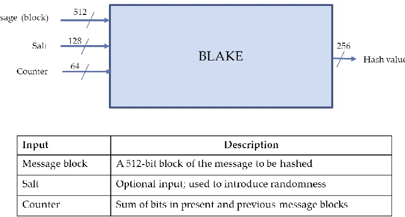
A top-level diagram of Blake-256 with its inputs and outputs is shown in figure 1 below
(when we make reference to the Blake hash function, we normally refer to its core functionality
alone as depicted in figure 1; that is the unit that hashes only individual message blocks). The
main input to the hash function is the message block input and the main output is the digest (or
hash value). The message block input takes in a 512-bit message block which may represent
text, image pixels or any kind of information. There are other inputs (salt and counter), one of
which is optional.
13 The salt input is an optional input that the user may utilize to introduce a user-controlled
parameter to compression of each message block. The salt is useful for randomized hashing. If
the salt is not used, its value is simply set to 0. For this work of speed optimization, we will not
make use of the salt. The counter input adds an extra security layer to the hash function. We
shall take a closer look at the counter in a later section.
The designers of Blake did not re-invent the wheel; rather they put together
components which had been previously analyzed and found to be secure and effective to form
Blake. Blake works in an iterative manner just as most hash functions do; that is, the hash code
of the previous message block is fedback to the input of the hash function for the compression
of the next message block. However, Blake follows the Hash Iterative Framework (HAIFA)
method proposed by Biham and Dunkelman [11] and not the Merkle-Damgard (MD) iteration [7]
mode. HAIFA is an improved version of the MD construction. Blake does not follow HAIFA fully,
but it borrows from it. The main ideas behind HAIFA are the introduction of the counter, a
special initial value (IV) for each digest size and a salt to the input of the compression function.
Also the length of the digest is included (in addition to the length of the message) in the padding
of the message. The Merkle-Damgard construct only includes the length of the message in the
padding. With Blake following the HAIFA iteration mode, it is able to provide resistance to
certain attacks that the MD construct could not adequately prevent such as length-extension.
Blake's internal structure is called a local-wide pipe structure [4]. The wide pipe
construction [12] is a type of structure in which the internal state of the hash function (from
which the hash value is extracted) is much larger (in number of bits) than the hash value. The
local-wide pipe was inspired by the wide-pipe structure; in local-wide pipe, the large internal
state is initialized from an initial value (or chain value), a salt and a counter. The advantage of
14 function borrows heavily from Daniel J Bernstein's stream cipher named "chacha". Bernstein, a
professor of mathematics at the University of Illinios at Chicago also submitted a SHA-3
candidate known as Cubehash to NIST, but Cubehash was eliminated in the second round of the
competition. Blake's compression function is actually a modified 'double round' of chacha [4].
It’s a modified version because the designers of Blake added the input of a message word and a
constant to the original chacha function. Chacha had been previously analyzed by Aumasson
(one of the designers of Blake). From his analysis, Aumasson became convinced of the
remarkable simplicity and security of chacha, leading to the adoption of chacha in Blake. Chacha
was designed to be immune to all kinds of side-channel attacks and Blake automatically
inherited this property. Side channel attacks are attacks which do not attack the compression
function but attack its implementation on systems which leak data (such as timing and power
analysis information). For example, the power consumption trace of a program running in a
microcontroller is full of information. Chacha's performance was found to be excellent during
the analysis and it was found to be strongly parallelizable. Again, Blake inherited these
properties and this makes it an efficient hash function.
The first step in hashing a message with Blake is to pad the message and break it into
blocks of 512 bits. The details of the padding are explained in the next section. The block size of
Blake-256 is 512 bits but the word size is 32 bits; thus each message block contains 16 words.
Blake’s algorithm initializes an internal state from the initial (or chain) value and other input(s)
(salt, counter) and then updates this internal state in a number of rounds by performing
computations on the state in each round using pieces (words) of the message block and some
constants. The salt input, when not used is set to 0; thus it acts as a constant for the initialization
of the internal state. After the rounds of state update have been all been completed, a
15 code could be the digest for the message or it could simply be an intermediate or chain value
which will be used as the initial value for the initialization of the internal state for the next
message block. However, if message block being processed is the last message block of the
message, then the hash value obtained at the finalization stage is the digest of the message.
2.2.1 Message padding
A message is padded before hashing it for a number of reasons; first of all, the message
is padded so that it can be divided into an integral number of blocks. For example, if a message
has 592 bits, without padding the first 512 bits of the message can be placed in a block but then
80 bits are left ‘hanging’. To solve this kind of problem, the message is padded to make it a 1024
bit message. Now it can be divided into 2 blocks. Padding is done by appending a number of
zero and one bits at the end of the message. Padding is also done to embed certain properties
of the message into the last message block. This enhances the security of the hash function
against certain types of attacks. In Blake, a message (M) is padded by first extending its length,
|M|, such that |M|= 447 mod 512. In effect, this means the remainder when |M| is divided by
512 is 447. This length extension is done by appending a '1' bit to the end of the message
followed by a sufficient number of ‘0’ bits. Having achieved length extension, the size of the
digest and length of the message are then embedded into the message. 512-447 = 65; 64 bits
are used to embed the length of the message while 1 bit is used to embed the size of the digest.
The digest size is set to 1 for Blake-256, Blake-512 and set to 0 for Blake-224, Blake 384. Thus
the padding operation can be summarized as
M <- M&1&00000...&|d|&|M|
where |d| is the digest size, |M| is the length of the original (unpadded) message; and ‘&’
16
2.2.2 Counter
The counter is an input that springs from the HAIFA iteration mode specification. Most
of the recent proposals on the way compression functions are to be iterated such as randomized
hashing and the enveloped Merkle-Damgard construction can all be instantiated as part of
HAIFA. The counter represents the sum of the number of message bits that have been hashed so
far and the number of message bits in the current block to be hashed. HAIFA makes the
compression of each block a function of the counter. That is hi = C (hi-1, mi, #bits, salt) where
‘#bits’ is the counter. This provides extra security against fixed-point attacks. A fixed-point is an
initial value and message block pair (h, m) which when inputted to the hash function (H) gives H
(h, m) = h. That is the hash code computed for an initial value and a message block is the same
as the initial value. A collision may be obtained if a fixed-point is found because m and m&m
will give the same hash code. With the inclusion of the counter as an input for each message,
the attacker is forced to work harder in order to find a point. Moreover, even if a
fixed-point of the form (h, m, #bits, salt) is found, so that h = (h, m, #bits, salt), the attacker cannot
concatenate m to itself and still get the same hash code because the counter (#bits) would be
different for m and m&m. The following example illustrates how the counter value for each
message block in the Blake hash function is determined: suppose we have a message with 1020
bits. After padding, this will be broken into 3 blocks of 512, 508 and 0 message bits. The term
'message bits' is important because in the second and third blocks there will be some padding
bits, but since we are only considering message bits, we do not consider these. Thus, the
counter value for the first block is 512; for the second block it is 512+508 = 1020. For the third
block, following the definition, we ought to have the counter value also set to 1020; however,
17 to 0 (irrespective of the number of bits that were previously hashed). Thus, for the third block in
our example, the counter value is set to 0.
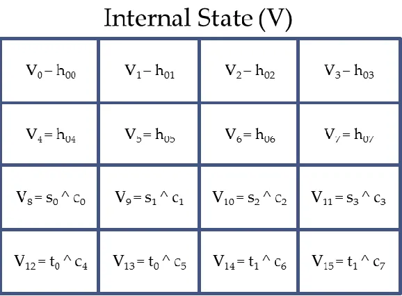
2.2.3 State initialization
The internal state of Blake has a local-wide pipe structure. The state is a 4x4 matrix of 32
bit state variables. Thus the state has 16 32-bit variables (or words). The internal state is a core
component of the Blake hash function. The inputs (apart from the message block) are used to
initialize the state; or in other words to determine the initial value of the state variables. The
initialization of some state variables is done by simply assigning the corresponding value of the
initial or chain value to the state variables. For some other state variables, the initialization is
18 done by first XORing a word of the salt and a constant or XORing a word of the counter and a
constant and then assigning the result to the state variable. Figure 2 illustrates the state
initialization for all the state variables. In figure 2, Vi represents a state variable; hoi represents a
word of the initial or chain value; si represents a word of the salt; ci represents a constant word
and ti represents a word of the counter.
2.2.4 State update
The algorithm of Blake updates the internal state once it has been initialized; this is
done by performing some operations on the state. These operations performed on the state
change the values of the state variables. The state update utilizes words of the message block
and it is performed by a compression function. Essentially the state update involves operations
like addition, rotations, XOR. The compression function of Blake which performs these
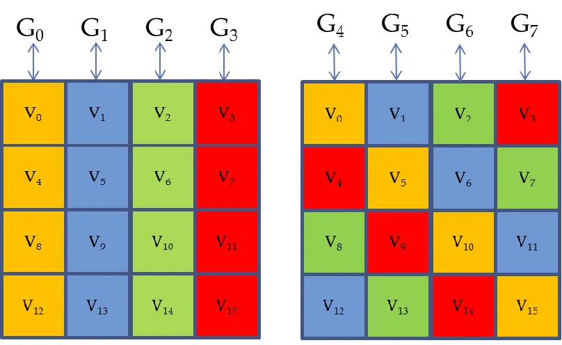
operations is called the g-function. The state is updated in a number of rounds. Each round
consists of some operations performed by the g-function on the state to update it. Since the
state is a 4x4 matrix; it has 4 rows and 4 columns. Each round of a state update can be broken
down into the update of the state’s columns and diagonals. These columns and diagonals of the
state are indicated by their distinct colours in figure 3. The state columns are first updated
starting from the first column on the left as indicated by the index of the g-function in the figure.
After all the columns have been updated, the four diagonals are updated in order. In Blake-256,
a full or complete state update consists of 14 rounds of state update. Since each round typically
takes one clock cycle, the full state update takes 14 clock cycles. A g-function operation on a
state column or diagonal utilizes 2 message words. Thus, each round of state update utilizes 16
message words (or 512 bits); in order words, each round of state update utilizes the entire
19
Figure 3 State update: columns and diagonals
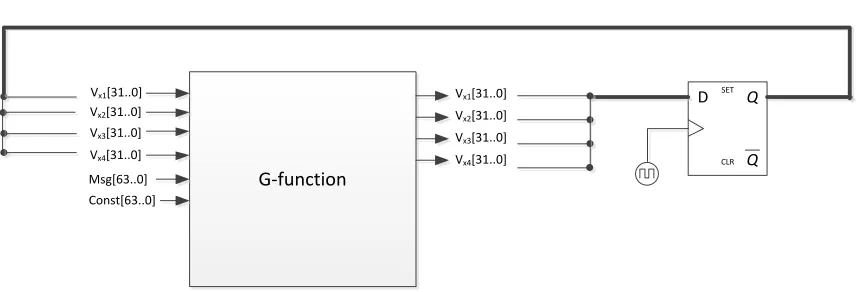
2.2.5 G-function
The g-function has the following inputs: 4 state variables, 2 message words and 2
constant words. It has 4 outputs which are same 4 inputted state variables. At the active clock
edge, new values are assigned to the state variables are stored; figure 4 illustrates this. The
g-function performs operations such as addition, rotation and XOR on the state variables. The
specific operations performed by the g-function depends on the column or diagonal of the state
that it is acting on (represented by the’ i’ subscript of the g-function) and the round number
20 Gi (Vx1, Vx2, Vx3, Vx4) at round, r, is evaluated as
vx1 = vx1+ vx2 + (mσr (2i) ^ Cσr (2i+ 1))
vx4 = (vx4 ^ vx1) >>> 16
vx3 = vx3 + vx4
vx2 = (vx2 ^ vx3) >>> 12
vx1 = vx1+ vx2 + (mσr (2i+1) ^ Cσr (2i))
vx4 = (vx4 ^ vx1) >>> 8
vx3 = vx3 + vx4
vx2 = (vx2 ^ vx3) >>> 7
In the operations described above, ‘>>>’ represents a rotation to the left and ‘^’ represents a
bitwise XOR operation. Vx1, Vx2, Vx3, Vx4 are state variables. From figure 3, the state column or
diagonal denoted by the subscript i in the notation Gi is evident. The message words (m) and
constants (c) utilized during a g-function computation are determined by a permutation table
named σ.
G-function
Vx1[31..0]
Vx3[31..0]
Vx2[31..0]
Vx1[31..0]
Vx4[31..0]
Vx2[31..0]
Vx3[31..0]
Vx4[31..0]
Msg[63..0] Const[63..0] Q Q SET CLR D
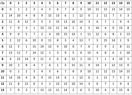
21 The permutation table σ can be visualized as a 2-dimensional array of integers. The first array
index specifies the row of the table, while the second array index specifies the column of the
table. The permutation table is displayed in table 1. The message block is also internally
represented as an array of message words m(0) to m(15); similarly, the constants employed in
the g-function are represented as an array of constant words c(0) to c(15). The notation mσr (2i)
represents a message word whose array index is determined by the permutation σr (2i). For
example, if the current round of the state update, r, = 2 and the second column of the state is
being updated (i = 1) then σr (2i) = σ2 2; from permutation table this gives a value of 12. Thus, mσr
(2i) = m (12).
r\c 0 1 2 3 4 5 6 7 8 9 10 11 12 13 14 15 0 0 1 2 3 4 5 6 7 8 9 10 11 12 13 14 15
1 14 10 4 8 9 15 13 6 1 12 0 2 11 7 5 3
2 11 8 12 0 5 2 15 13 10 14 3 6 7 1 9 4
3 7 9 3 1 13 12 11 14 2 6 5 10 4 0 15 8
4 9 0 5 7 2 4 10 15 14 1 11 12 6 8 3 13
5 2 12 6 10 0 11 8 3 4 13 7 5 15 14 1 9
6 12 5 1 15 14 13 4 10 0 7 6 3 9 2 8 11
7 13 11 7 14 12 1 3 9 5 0 15 4 8 6 2 10
8 6 15 14 9 11 3 0 8 12 2 13 7 1 4 10 5
9 10 2 8 4 7 6 1 5 15 11 9 14 3 12 13 0
10 0 1 2 3 4 5 6 7 8 9 10 11 12 13 14 15
11 14 10 4 8 9 15 13 6 1 12 0 2 11 7 5 3
12 11 8 12 0 5 2 15 13 10 14 3 6 7 1 9 4
13 7 9 3 1 13 12 11 14 2 6 5 10 4 0 15 8
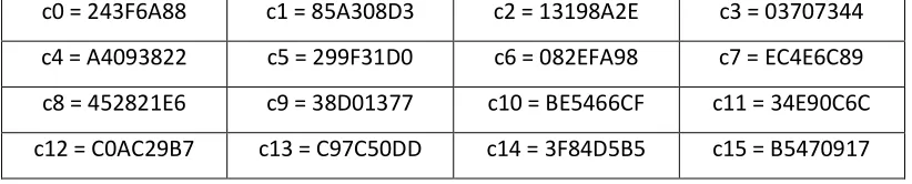
22 The constants utilized in the g-function (such as Cσr (2i)) are determined in a similar manner. The
array of 16 constants is given in table 2 below:
c0 = 243F6A88 c1 = 85A308D3 c2 = 13198A2E c3 = 03707344
c4 = A4093822 c5 = 299F31D0 c6 = 082EFA98 c7 = EC4E6C89
c8 = 452821E6 c9 = 38D01377 c10 = BE5466CF c11 = 34E90C6C
c12 = C0AC29B7 c13 = C97C50DD c14 = 3F84D5B5 c15 = B5470917
Table 2 Blake constants
2.2.6 Finalization
The finalization stage is the last process in the computation of the hash value of a
message block. This hash value (or code) may be a chain value or the digest of the message. In
this stage, the hash value is extracted from the updated state. The salt (s) and initial value (hi-1)
which were used to initialize the state are again used in the extraction of the hash code, but the
counter is not used.
23 As previously mentioned, when the salt input is not used, its value is set to 0 and it simply
functions as a constant. Essentially, a set of XOR operations are performed using the initial
value, salt and 2 state variables as shown in table 3 in this stage. Table 4 gives the initial values
used for the first block of a message (referred to as the initialization vector) in both the state
initialization and the finalization processes. It may be recalled from previous discussions that for
subsequent message blocks the initial value is given by the hash code (chain value) of the
previous message block.
IV0 = 6A09E667F3BCC908 IV1 = BB67AE8584CAA73B
IV2 = 3C6EF372FE94F82B IV3 = A54FF53A5F1D36F1
IV4 = 510E527FADE682D1 IV5 = 9B05688C2B3E6C1F
IV6 = 1F83D9ABFB41BD6B IV7 = 5BE0CD19137E2179
Table 4 Blake’s Initialization Vector (IV)
2.3 Implementations of Blake
Blake has already been implemented on a wide variety of platforms. These include
software implementations using C, Python, Matlab; hardware implementations with Application
Specific Integrated Circuit (ASIC) and FPGA. In FPGA, Blake has been implemented on devices
from the two main FPGA vendors (Altera and Xilinx). In these platforms there have been efforts
to optimize the speed of operation of the hash function since this has huge advantages
particularly when hashing a large amount of messages in the various information security
24 In the next chapter we shall examine the speed optimizations that have already been done in
25
CHAPTER 3
3.
Previous works on high-speed implementation of Blake
Certain techniques have been applied to hardware implementations of Blake in an
attempt to optimize the speed of the hash function. These techniques are: parallelism,
pipelining and the use of fast adders. In the following sections we shall examine each of these
techniques.
3.1 Parallelism
Parallelism [5] is one of the methods that have been applied for the speed optimization
of Blake. The main task that consumes time in the hash function’s algorithm is the state update.
The initialization is a process that simply depends on a few XOR gates and combinational logic;
this doesn’t consume time. Similarly, the finalization is a process that depends on XOR gates and
utilizes only combinational logic; it consumes a relatively small amount of time. However, for
the state update; first of all it utilizes the g-functions which have addition, rotation operations;
these can consume some time. Secondly, the full state update takes 14 rounds of similar
g-function operations. Thus, if the speed of the hash g-function is to be increased, one of the main
areas to consider would be the state update. The update of the state columns and diagonals can
be done sequentially; that is, one column (or diagonal) updated at a time or it could be done
with all 4 columns updated simultaneously. However, all the columns must be updated before
the diagonals are updated because the diagonal update makes use of the new state variable
values obtained from the column update. Parallelism is applied to Blake by updating all the
26 simultaneously. This requires atleast 4 g-functions; alternatively 8 g-functions may be used,
however the last four g-functions will be dependent on the first 4 g-functions for their inputs in
this case. The speed of the hash function is improved by a factor of 4 through parallelism.
3.2 Pipelining
In the g-function, some of the operations performed could take a relatively long period
of time. The g-function is a modified ‘double’ round of the stream cipher chacha. The fact that it
is a double round implies that the outputs of some operations in the g-function are inputs to
some other operations in the same g-function. In particular, computations involving the XOR of
message and constant words, one of which is given below:
vx1 = vx1+ vx2 + (mσr (2i) ^ Cσr (2i+ 1))
consume a longer time because there are three major operations involved. Thus, these
operations constitute the critical path of the g-function (the path with the longest delay).The
critical path influences the speed (throughput) of the overall computation. A long critical path
delay requires a long the clock period and hence the speed of the hash function is reduced.
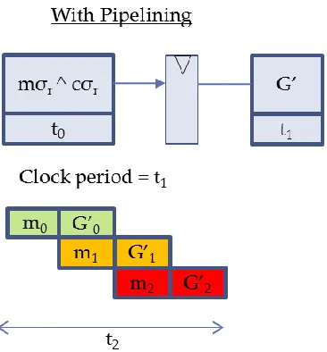
However, a pipeline stage may be used to improve the speed. Since there are 14 rounds of
repeated function computations, if a pipeline register is inserted into the critical path of the
g-function; thereby creating a two stage pipeline, then the first stage of the pipeline for the next
round can be executed while the second stage of the pipeline for the current round is executing.
The net effect is an increase in the clock rate and consequently an increase in speed
(throughput) of the hash function. This pipeline technique was applied in [6]. Figure 5 illustrates
27
Figure 5 Pipelining applied to Blake
As seen in figure 5, when pipelining is applied, 3 g-function computations were accomplished
within a time period of t2; whereas without pipelining only 2 g-functions were accomplished
within the same time period.
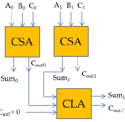
3.3 Fast adders
The third technique that has been applied for speed optimization in Blake is the use of
carry-save and carry-lookahead adders in the g-function. These are fast adders. The technique
was applied in [6]. Carries are a major source of delay in additions when ripple adders are used
because a carry needs to propagate to the last full adder before the sum can be considered
valid. The additions in the g-function of Blake are 32-bit additions; thus if ripple adders are used,
then the time it takes for a carry to propagate from the full adder (FA) at the least significant bit
28 overcome this source of delay, 2 carry-save adders (CSA) are used when three numbers are to
be added, with a carry -lookahead adder (CLA) performing the final stage of the addition. This is
shown in figure 6 for a 2 bit number. The CSA is a FA connected in such a way that it adds
corresponding bits of the 3 numbers directly similar to the way we add numbers on paper. This
saves a significant amount of time since the few carries generated are added with a CLA. The
arrangement can be easily extended to 32 bits.
29
CHAPTER 4
4.
Proposed design
The speed optimizations techniques discussed in the previous chapter essentially focus
on the process of hashing one message block. These techniques are effective and aim at
reducing the time spent in hashing each message block, thereby reducing the overall time spent
in hashing a message which may contain many blocks. For example, if the time spent in hashing
a message block has been reduced through the use of fast adders from 50ns to 45ns and there
are 1000 messages to be hashed, each containing 10 message blocks; the minimum time that
would be spent in hashing these messages would be reduced from 0.5ms to 0.45ms. Thus, the
speed has been improved. A similar analogy holds for the techniques of parallelism and
pipelining. However, there is a particular situation in which the speed of the hash function can
be potentially increased further but these techniques cannot bring about the improvement. This
situation occurs when many messages which have some identical message blocks are to be
hashed. For instance, if message blocks 1 and 2 out of the 10 message blocks in the messages of
our previous example are identical but message blocks 3 to 10 are different, these messages will
still give distinct hash codes. However, the chain values (intermediate hash values) obtained for
message blocks 1 and 2 will be the same for all the messages. The implication of this, is that in
computing the digests of the 1000 messages, the hash function will perform the same
computation 2,000 times (the hash code of message block 1 will be computed 1000 times, the
same goes for message block 2, so in total there will be 2,000 identical or repeated
30 lead to a significant increase in speed; the time taken to compute the hash codes would be
reduced by an additional 0.1ms.
Our design takes the situation in which messages with common blocks are to be hashed
into consideration and provides a way of bypassing the redundant computations that would
otherwise have to be made; thus providing high speed operation. The design allows the
previously discussed techniques of parallelism, pipelining and fast adders to be applied to the
Blake hash function but in addition it provides a method of avoiding redundant computations,
thereby leading to a further increase in the speed of the hash function. The design is
self-learning; that is, it builds up its knowledge of common message blocks without intervention
from the user. The design incorporates three major components to facilitate these:
1. Message preprocessor: This component independently identifies common message
blocks in the messages that are being hashed, determines their initial values, counter
values and computes their hash codes.
2. Memory: A memory device is used to store the hash code of any common message
block that has been identified by the message preprocessor.
3. Decoder: This component is used to determine if an inputted message block is a
common message block. If the inputted message block is a common message block, the
decoder outputs the address of the memory location containing the hash code of the
common message block. In addition, it also outputs a signal which indicates to the hash
function unit that the hash code of the inputted message block is already available in
memory and consequently, there is no need to compute it.
In the following sections we shall discuss each of these components and how they interconnect
31
4.1 Message preprocessor
The message preprocessor is a microprocessor with software running on it to perform
the function of identifying any common message blocks within a sequence of messages. It has to
be able to run independently; that is it should run concurrently with the hashing of the
messages so that it does not delay or disrupt the hashing of the messages. In order to achieve
this, the external memory device from which the messages to be hashed are fetched should be a
multiport memory device, so that the message preprocessor has an independent access to the
messages through one of its ports and the rest of the system also has access to the same
messages through another port of the memory.
The preprocessor initializes reconfiguration of the decoder whenever this is required.
Figure 7 shows a block diagram of the preprocessor. An example of a preprocessing algorithm
would be to place 10 messages occurring in sequence in arrays; with each array element
containing a message block. A 3-dimensional array could be used to place the messages into
blocks; the first array index representing the message, the second array index representing the
message block and the third array index representing the individual bits of a message block. A
Message Preprocessor Multiport Memory
P
o
rt
A
Port B Port C
Reconfig_data Reconfig_init
32 comparison can then be made between message blocks at corresponding array positions to
determine if any of them have identical initial values and identical contents. The term “common
message block” refers to a message block that has not only identical content with another (or
multiple) message block(s), but also has identical counter and initial values. Thus if message
blocks 1, 2 and 4 are identical for 2 messages, we can bypass the computation of the hash codes
for message blocks 1 and 2 in the second message by using the results obtained from the first
message but we cannot bypass the computation of message block 4 because it will have
different initial values for both messages and consequently different hash codes. It should be
noted that the counter value for two identical message blocks at the same block position with
the same initial value will automatically be the same.
After identifying any common blocks in the messages through comparison, the
preprocessor will independently compute the hash codes of the common blocks (a separate
hash peripheral will be utilized for this so that the normal hash process of the messages remains
undisrupted). These hash codes will then be used to reconfigure the memory device and the
corresponding message blocks, initial values and counter values will be used to reconfigure the
decoder. The algorithm for these tasks can be written in C (or any other suitable programming
language).
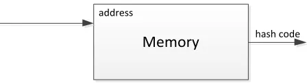
4.2 Memory
A memory device is required for storing hash codes of common message blocks that
have been identified by the preprocessor. The word size of the memory should be 256 bits in
order to accommodate the 256-bit hash codes. However, a large number of memory words is
typically not required since only a limited number of hash codes are expected to be stored at
33 illustrates the function of the memory device. Hash codes are placed in memory locations
through run-time reconfiguration. This reconfiguration is initiated by the preprocessor and
carried out by a reconfiguration processor.
Memory
address
hash code
Figure 8 Memory
4.3 Decoder
When a message block is to be hashed, there needs to be a way of determining if the
block is one of the common blocks that have been identified by the preprocessor and whose
hash code has been stored in memory. If the block is one of such common blocks, then the
address of the memory location where its hash code has been stored needs to be determined.
Furthermore, a signal needs to be sent to the hash function computation unit to inform the unit
that no computation needs to be made for that message block and that a valid output signal can
be generated since the hash code is already available. In this way the entire 14 rounds of
computations that would otherwise be required are skipped. The decoder performs these tasks.
As shown in figure 9, the decoder can be visualized as an m-bit to n-bit code converter.
That is, it maps the bit codes present at its input to corresponding n-bit output codes. The
34 Thus, it is an 831-bit code (512 bits for the message, 256 bits for the initial value, and 64 bits for
the counter).
Decoder
Message
Initial Value
Memory Address
Match
Counter
M
-b
it N
-b
it
Figure 9 Decoder
The n-bit code represents the address of the memory location with the hash code of the
message block contained in the input m-bit code, concatenated with a “match” signal. This
match signal when activated indicates that a hash code is present in memory for the inputted
message block. Thus it can be used to inform the hash function unit to skip computations for
that message block.
Essentially, the decoder is created by a truth table with an m-bit input code and n-bit
output code. Since we are only concerned with specific m-bit codes corresponding to specific
message blocks, initial values and counter values, all other possible m-bit code combinations will
be represented by ‘don’t care’ values (X) state in the truth table. Likewise since we want the
match signal to be activated only when specific m-bit codes are inputted, the match signal is
deactivated (set to 0) for all don’t care inputs; similarly, the memory addresses corresponding to
don’t care inputs are assigned don’t care values since they are not utilized in such cases. An
example of a truth table which can be used to configure the decoder is given in table 5. All the
35
Table 5 Sample decoder truth table
Arbitrary values can be utilized in the decoder’s truth table when the system is
implemented. However, as the message processor begins to discover common message blocks,
the decoder needs to be reconfigured on the fly so that it can recognize these common message
blocks; therefore its truth table needs to be updated at time. This is achieved through
run-time reconfiguration. The run-run-time reconfiguration is initiated by the message preprocessor and
carried out by a reconfiguration processor. In order for the decoder and memory device to be
run-time reconfigurable, they should be implemented in a partially reconfigurable block of the
FPGA. All other components of the system should be placed in static blocks within the FPGA.
Message Block [511..0] Initial Value [255..0] Counter [63..0] Address[3..0] Match
1aef89712137b3dac890 93ef89712137b3dac890 2eaf89712137b3dac890 1a0f59712137b3dac890 5aef89712137b3dac890 33ef69712137b3dac890 47809001 6a09e667bb67ae85 3c6ef372a54ff53a 510e527f9b05688c 1f83d9ab5be0cd19 000000000000 512
1 1
11ea85610197b3decff0 53e080317139b3dfcfff 2eaf89712137b3dac8ff 1a0f59702137a3dac8ff 5aef89702137a3dac8ff 33ef69702137a3dac8ea 40808001 0ce8d4ef4dd7cd8d 62dfded9d4edb0a7 74ae6a41929a74da 23109e8f11139c87 000000000000 512
2 1
36
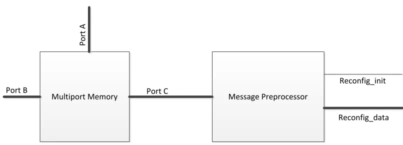
4.4 System
The overall system consists of all the above mentioned components interconnected to
achieve the desired goal. A top-level block diagram of the system is given in figure 10. Figure 11
Figure 10 System block diagram
shows more details of the interconnections between certain of the components of the system.
From figure 11, it is evident that the decoder selects the address of the memory location
containing the hash code corresponding to the inputted message block, counter value and initial
value. The ‘match’ signal, which is also generated by the decoder, is used as a select input of a
37 signal is activated (set to 1); otherwise it selects the hash code obtained from the hash function
computation unit.
Decoder
Memory
Original Blake
Message Block
Initial Value
address
match
sel
Inp1
Inp0
Output match
hash code Counter
Figure 11 Details of some system interconnections
The system is self-learning. Initially, it has no knowledge of common message blocks
(assuming the decoder is initially configured with arbitrary values), but as messages are hashed,
the message preprocessor begins to discover common message blocks. The preprocessor then
sends appropriate signals to the reconfiguration processor to reconfigure the decoder and
memory using the newly discovered common message blocks and hash codes. Thus, in this
manner, the system builds up its knowledge of common message blocks.
From figure 10, we note that the Blake hash function is connected as a peripheral for a
processor labelled ‘hashing’ processor. With this arrangement, the processor serves as an
interface between the hash function and the external memory containing messages to be
hashed. The Blake hash perpheral only hashes single message blocks, thus in order to hash a
message, the hashing processor needs to break down the message into blocks. The hashing
38 message blocks. It transfers the message block words along with the associated initial and
counter values to the Blake peripheral in a serial manner. The name ‘peripheral’ here implies a
device that is loosely attached to the processor; that is, it has some level of independence from
the processor. It can perform multi-cycle operations without interference from the processor. A
custom instruction on the other would imply a device that is closely attached to the processor.
The hashing processor retrieves the chain value from the Blake peripheral after the hash of the
message block has been completed and applies it as the initial value for the next message block.
It therefore supervises or conducts the entire hash operation.
39 As mentioned earlier, the match signal is used to skip computations in the Blake
peripheral when a ‘known’ message block is inputted. The mechanism by which this occurs
deserves further explanation. Figure 12 shows an algorithm state machine (ASM) chart for the
controller unit within the Blake peripheral. The figure shows the ASM chart of the controller for
both the original Blake design and the proposed design. Comparison of the two charts shows
that the main difference is in the addition of a decision box containing the match signal in the
proposed design. This match signal, when activated with the controller in the IDL state, sets the
next state as FIN. Thus, at the active clock edge, the controller proceeds to the FIN state,
skipping the RND state. The computations of the g-functions occur only when the RND state is
activated; thus by skipping the RND state these computations are bypassed. At the FIN state, a
‘data valid’ signal labelled “VALIDOUT” is outputted. This signal indicates that the hash code has
been successfully obtained (either by computation or through retrieval from memory). Figure 13
illustrates how the FIN state can be implemented for both the controllers, using one-hot
encoding. Q Q SET CLR D FIN ROUND[3] ROUND[2] ROUND[1] ROUND[0] CLOCK Q Q SET CLR D FIN ROUND[3] ROUND[2] ROUND[1] ROUND[0] CLOCK IDL MATCH
Original Controller Unit
Proposed Controller Unit VALIDIN